ARTICLE International Journal of Advanced Robotic Systems
Hand Motion-Based Remote Control Interface with Vibrotactile Feedback for Home Robots Regular Paper
Juan Wu1, Guifang Qiao1, Jun Zhang1, Ying Zhang1 and Guangming Song1,* 1 School of Instrument Science and Engineering, Southeast University, Nanjing, China * Corresponding author E-mail:
[email protected] Received 9May 2012; Accepted 3May 2013 DOI: 10.5772/56617 © 2013 Wu et al.; licensee InTech. This is an open access article distributed under the terms of the Creative Commons Attribution License (http://creativecommons.org/licenses/by/3.0), which permits unrestricted use, distribution, and reproduction in any medium, provided the original work is properly cited.
Abstract This paper presents the design and implementation of a hand-held interface system for the locomotion control of home robots. A handheld controller is proposed to implement hand motion recognition and hand motion-based robot control. The handheld controller can provide a ‘connect-and-play’ service for the users to control the home robot with visual and vibrotactile feedback. Six natural hand gestures are defined for navigating the home robots. A three-axis accelerometer is used to detect the hand motions of the user. The recorded acceleration data are analysed and classified to corresponding control commands according to their characteristic curves. A vibration motor is used to provide vibrotactile feedback to the user when an improper operation is performed. The performances of the proposed hand motion-based interface and the traditional keyboard and mouse interface have been compared in robot navigation experiments. The experimental results of home robot navigation show that the success rate of the handheld controller is 13.33% higher than the PC based controller. The precision of the handheld controller is 15.4% more than that of the PC and the execution time is 24.7% less than the PC based controller. This means that the www.intechopen.com
proposed hand motion-based interface is more efficient and flexible. Keywords Hand Motion Recognition, Home Robot, Control Interface, Handheld Controller
1. Introduction In recent years, more and more mobile robots have moved away from industry to enter home environments. As the size and the cost have decreased significantly, the home robot is now available for use as one of the most popular consumer electronic products [1]. More and more home robots are now working around us and they help us a lot in our daily lives. A wide variety of home robots have been proposed to do housework such as cooking, cleaning, houseplant watering and pet feeding. They are also being widely used in home security, entertainment, rehabilitation training and home care for the elderly [2-5]. As the home robots get closer in our daily lives, the question arises: How to interact with them? Complicated control interfaces designed for skilled
Int JZhang, Adv Robotic Sy, 2013, Vol. 10, 270:2013 Juan Wu, Guifang Qiao, Jun Ying Zhang and Guangming Song: Hand Motion-Based Remote Control Interface with Vibrotactile Feedback for Home Robots
1
workers and experts are not suitable for ordinary home users. They prefer simple and natural interaction with home robots through voices and gestures. This requires a user-friendly interface that allows the robot to understand voice and gesture commands. The voice interface is suitable for a simple call-and-come service for home robots [6] but it is not suitable for continuous remote control and usually it cannot work normally due to the interference of ambient noise. Therefore, hand gesture or hand motion-based interfaces are more suitable for control of home robots. Several methods have been proposed for hand gesture recognition, such as marker-based gesture recognition, vision-based motion recognition, haptic-based motion recognition and EMG-based hand motion recognition [7]. In [8], a real-time hand gesture recognition system based on difference image entropy using a stereo camera is introduced. The proposed method shows an average recognition rate of 85%. Other hand gesture recognition methods use wearable sensors, accelerometers, angular rate sensors and data gloves to detect hand gestures. In [9], a data glove is used for 3D hand motion tracking and gesture recognition. In [10], the authors proposed a set of recognition algorithms: TC, FAcaGMM and FEC. They evaluated the algorithms on a data glove with 13 different types of grasps and ten in-hand manipulations. In [11-12], the authors used a wearable sensor to recognize hand gestures and daily activities in a smart assisted living system to help elderly people, patients and the disabled. In [13], a wearable wristwatch-type controller is introduced to offer a unified way to control various devices. The controller uses simple and effective hand motion gestures for controlling devices. In [14], an accelerometer combined with a visual tracker is used to detect hand movements in a system for human computer interaction. As compared to the wearable sensor-based control interface, the handheld interface is more suitable for controlling home robots. Since people are used to this kind of control mode they can learn to use it quickly and easily. Wearable sensors fixed on the body of a person are not convenient and flexible to use when he or she wants to control a robot. In [15], the authors introduce a handheld interface system for 3D interaction with digital media contents. The system can track the full six degreesof-freedom position and orientation of a handheld controller. The gesture recognition depends on acceleration and position measurements. A hand-gesturebased control interface for navigating a car robot is introduced in [16]. A three-axis accelerometer is adopted to record the hand trajectories of a user. In [17-18], the authors proposed a handheld system to recognize hand motions. The system contains three MEMS accelerometers and a Bluetooth wireless module. 2
Int J Adv Robotic Sy, 2013, Vol. 10, 270:2013
Hand gestures usually can be described by the tilt angles of the hand. So tilt sensors can be used to detect the angles of a hand gesture. In [19], a tilt sensor was designed using standard accelerometers. The accuracy of the tilt sensor is 0.3° over the full measurement range of pitch and roll. In [20], the authors used a Kalman filter to estimate inclination from the signals of a three-axis accelerometer for measuring inclination of body segments and activity of daily living (ADL). This method is nearly twice as accurate as the methods based on low-pass filtering of accelerometer signals. In [21], a three-axis accelerometer and a dual-axis angular rate sensor are utilized for orientation sensing in mobile virtual environments. It presents a technical and theoretical description for implementing an orientation-aware device, which is used for navigating large images spread out on a virtual hemispheric space in front of the user through a mobile display. In [22], a novel approach for hand gesture recognition is introduced. In [23], a hand gesture recognition system is implemented to detect hand gestures in any orientation. The system is integrated on an interactive robot, allowing for real-time hand gesture interaction with the robot. Gestures are translated into goals for the robot, telling him where to go. Vibration motors are usually used in handheld interfaces to provide vibrotactile feedback. In [15], a vibration motor and a voice-coil actuator are adopted to achieve vibrotactile feedback. In [24], vibrotactile actuators are used in a handheld input device for providing spatial and directional information. In [25], a vibrotactile feedback approach for posture guidance is introduced and in [26], multi-day training with vibrotactile feedback for virtual object manipulation is introduced. Experimental results show that participants are able to utilize the vibrotactile feedback to improve the performance of virtual object manipulation. In this paper, we present a hand motion-based remote control interface with vibrotactile feedback for home robots. A handheld controller is proposed to implement hand motion recognition and hand motion-based robot control. The handheld controller can provide a ‘connectand-play’ service for the users to control the home robot. Meanwhile, it implements the function of visual and vibrotactile feedback. Six simple hand gestures are defined for locomotion control of the robot. They are easy to use for untrained people. A three-axis accelerometer is used to detect the hand motions of the user. The recorded acceleration data are analysed and classified to corresponding control commands according to their characteristic curves. A vibration motor is used to provide vibrotactile feedback to the user when an improper operation is performed. The remainder of this paper is organized as follows. Section 2 introduces the overall system architecture that www.intechopen.com
includes the handheld con ntroller and the home robot.. The hardware deesign of the haandheld contrroller is preseented in Section 3. T The methods of hand motio on recognition n and hand motion n-based robot control are prresented in Secction 4. The experrimental resu ults on the pe erformance off the prototype sy ystem are giv ven in Sectio on 5. Conclu uding remarks are g given in Sectio on 4.
k userr interface (GUI) and a vibrotacttile feedback geneerator. The embedded e prrogram in th he robot can n imp plement basic locomotion bbehaviours an nd other high-leveel behaviours such as vid deo transmission, cruising,, dock mation and thee king and recharging. The obbstacle inform currrent status of the robot are also useful when w no wall-mou unted or ceilin ng-mounted caameras are available.
2. System desscription The conceptu ure of the ha and motion b based ual architectu control system m is shown in n Figure 1.
Figure 1.Concceptual system architecture. Th he user controlls the he hand motion ns are robot by rotatiing the handhelld controller. Th recognized by the handheld controller c and converted c to m motion commands.
The system cconsists of a handheld h conttroller and a h home surveillance robot. The haandheld contrroller has a th hreeometer and a vibration motor for user axis accelero interaction. IIt can sense the accelerations of the h hand motions of th he user and co onvert those acceleration a vaalues to robot con ntrol command ds. The comm mands are sen nt to the robot to implemeent various motion con ntrol applications. There are three alternative schemass for establishing wireless com mmunication links l between n the handheld con ntroller and the t robot, i.e.,, Wi-Fi, Bluettooth and TCP/IP. The home surveillance s robot used in n our hown in Figurre 2. It is a palm-sized p moobile system is sh urity robot with an on-board d camera fo or home secu d design work k of this robott has applications. The detailed been presented in [5].
Figu ure 3.Software sttructure of the hhand motion-ba ased control systeem.
3. Handheld H controller A prototype of th he handheld coontroller is sho own in Figuree T size of the controller is 137mm×90mm m×31mm and d 5. The its weight is ab bout 250g. Th he handheld controller iss porttable equipme ent designed ffor controlling g home robotss by hand motio ons. It inclludes a corre board, a u (MCU), a three-axis acccelerometer, a microcontroller unit Wi-Fi adapter, a touch screeen, two USB ports and a a shown in Fiigure 4. vibrration motor, as
Figu ure 4.Hardware structure of thee handheld conttroller.
Figure 2.The h home surveillance robot.
The softwaree structure of the control sy ystem is show wn in he embedded Figure 3. Th d programs in the hand dheld controller incclude a hand motion recog gnizer, a graph hical www.intechopen.com
The core board is i a small em mbedded com mputer system m m of the communication interfacess thatt provides most need ded here. A standalonee MCU is adopted forr acceeleration acquisition and prrocessing in orrder to ensuree good real-time performance. p It communicates with thee coree board throu ugh a serial p port. Users ca an access thee Inteernet via th he Wi-Fi ad dapter for remote r robott conttrolling. Therrefore, the coontroller can provide thee ‘con nnect-and-play y’ service foor the users. And it can n
Juan Wu, Guifang Qiao, Jun Zhang, Ying Zhang and Guangming Song: Hand Motion-Based Remote Control Interface with Vibrotactile Feedback for Home Robots
3
provide suffficient bandwiidth for video o transmissioon. A LCD module is used to giv ve necessary v visual touchscreen L feedback forr the users to o implement remote r controol. It also allows touch input for the userss to manage and configure thee control systeem.
4.2 Hand H Motion Recognition R The handheld co ontroller is a 33D rigid body that can bee rota ated about th he three orthoogonal axes. According to o avia ation terminology, these rottations will be referred to ass yaw w, pitch and roll. The orien ntation of the rigid body iss often represente ed by usingg Euler angles that aree mposed of tho ose three elem mental rotation n angles. Thee com firstt rotation abo out the Z-axiis is called yaw, y the nextt rota ation about th he X-axis of iss called pitch h and the lastt rota ation about th he Y-axis is caalled roll. An ny orientation n can be achieved d by composiing those thrree elementall ations. rota In our o work, all of the planneed hand motiions for robott conttrol are simplle gestures, eaach of which contains only y one of the three elemental rotaations. Gesturres composed d m than one e elemental rootation are too o complicated d of more for this kind of o application n. The real--time controll perfformance is not accep ptable when too many y com mplicated gestu ures are used.. It will also be b too difficultt for the t user to lea arn and use. SSo we directly y use the threee mea asured accelerration values to describe th he rotation off the handheld con ntroller.
Figure 5.Impleemented prototy ype of the handheld controller.. The size of the han ndheld controller is 137mm×90m mm×31mm weight is 252g. (L×W×H). Its w
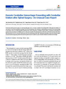
4. Hand motiion-based con ntrol 4.1 Coordinatee System The first step p to implemeenting hand motion m recogn nition by the handh nition of referrence held controlleer is the defin frames. Thee three-dimeensional Carttesian coordiinate system of th he handheld controller c is sh hown in Figu ure 6. The three-axiis accelerometter is assumed d to be fixed too the origin of th he coordinate system and its sensing axes coincide with h the axes dep picted in Figu ure 6. The possitive direction of the Z-axis is defined as th he direction g going evice. The possitive vertically out from the scrreen of the de he direction too the direction of the X-axis is defined as th when a user holds h the dev vice and seess the right side w screen. Then n, the positive direction of the Y-axis wiill be h the device iss pointing. the front direection in which Figu ure 7.Hand mottion set for conntrolling the ho ome robot. Thee conttroller is in the right hand of tthe user in this example. R (L)) represents the command to turn tthe robot right (left) when thee userr tilts the controller to the rigght (left). F (B) represents thee command to move the robot forwaard (backward)) when the userr tilts the controller forward (baackward). U represents thee command to make a U-turn wheen the user tiltss the controllerr 180° to the right. S represents thee command to stop when thee userr tilts the controlller 180° to the lleft. Figure 6.3-dim mensional coordinate system of the handheld controller. 4
Int J Adv Robotic Sy, 2013, Vol. 10, 270:2013
We have designe ed six simplee hand motio ons for homee ot navigation and control, as shown in Figure 7. Thee robo www.intechopen.com
hand motion n patterns are all commonly y used in daily y life. A user can eaasily repeat all these actionss well withoutt any special trainiing. There is a significant difference d betw ween any two of th he hand motio on patterns, so it is easy fo r the handheld co ontroller to accurately diistinguish am mong different han nd motion paatterns. Then we can tran nslate these hand motions to correspondin ng robot con ntrol commands. T This kind of usser interface design d allows u us to ensure that a user-indepen ndent and use er-friendly con ntrol system is imp plemented.
Thee six hand mo otion trials, w which are shown in Figuree 7, have h been carrried out to ggather typicall acceleration n data a to assess the accelerration chara acteristics off different hand motions. Example pllots of thee anges duringg the hand motions aree acceeleration cha show wn in Figurres 8-13. Thee directions of the hand d mottions are re eflected by the variation trends off acceelerations in the t three axess.
mand to turn th he robot right (left) R (L) represeents the comm when the useer tilts the controller to the e right (left). F (B) represents th he command d to move th he robot forw ward (backward) w when the user tilts the controller c forw ward (backward). U represents the t command d to make a U--turn when the useer tilts the con ntroller 180° to o the right with h the back of thee controller facing up. S represents the command to stop when th he user tilts the e controller 1880° to acing up. the left with tthe back of thee controller fa Group
Xaxis 1 × X-axis × ↗ 2 Y-axis ↘ ↗, ↘ ↘,↗
Yaxis ↗ ↘ × × × ×
Hand d n Motion F B R L U S
Position of o MAX Finishing g Beginnin ng Finishing g Beginnin ng Middle ×
Position of MIN Beginnin ng Finishin ng Beginnin ng Finishin ng × Middlee
Figu ure 8.Acceleratio on characteristiccs of the R motion.
Table 1. Hand d motion charaacteristics for co ontrolling the h home robot. ‘↗’ reprresents that thee N-axis (N = X or Y) accelerration increases m monotonically. ‘↘’ repre esents decreeasing monotonically y. ‘↗, ↘’ represents increa asing at first and decreasing lateer. ‘↗, ↘’ is oppo osite to ‘↘,↗’
The handhelld controller continuously c recognizes th he six ns by analysin ng the accelera ation values oof the hand motion integrated acccelerometer. The accelerations in the tthree axes change ssimultaneouslly during the hand h motionss, but for any prop posed hand motion, m the accceleration in n one axis will chan nge little whille that in the other o two axess will change signiificantly as co ompared to the t previous one, because all th he proposed hand h motions are designed tto be either a sing gle roll rotatiion or a sing gle pitch rotaation. Based on tthis principlle, we can get the un nique acceleration characteristiccs of every hand h motion and therefore identify differentt hand motion ns. Hand R Robot Comman nd motion Header Length Motion M D/A Speed S R xAA 0x07 ‘R’ * * 0x L xAA 0x07 ‘L’ * * 0x F xAA 0x07 ‘F’ * * 0x B xAA 0x07 ‘B’ * * 0x U xAA 0x07 ‘U’ * * 0x S xAA 0x07 ‘S’ * * 0x
Tail C CRC 0x55 * 0x55 * 0x55 * 0x55 * 0x55 * 0x55 *
Table 2.The m mapping between n hand motion and a robot contrrol commands. www.intechopen.com
Figu ure 9. Acceleration characteristiics of the L motiion.
Figu ure 10.Acceleration characteristtics of the F mottion.
Juan Wu, Guifang Qiao, Jun Zhang, Ying Zhang and Guangming Song: Hand Motion-Based Remote Control Interface with Vibrotactile Feedback for Home Robots
5
almost unchanged during the R/L roll mottion while thee X-ax xis and the Z-axis Z acceleraations increase or decreasee sign nificantly.
Figure 11.Acceeleration characcteristics of the B motion.
i to comparee the variation n trends of thee The second step is otheer two axes to o determine w which the hand d motions are.. The variation tren nds of the six h hand motionss are shown in n Table 1. The algorithm of the vvariation trend ds recognition n is presented in Fiigure 14. The values of the e accelerationss h of each axis are sampled with a fixed 10ms interval. Each etected with a 1.5s time spa an. We can gett hand motion is de 50 acceleration n data sequen nce for each hand h motion.. a 15 The data from the acceleration n sensor firstly y need to passs the moving-avera age filter to m make the data curve changee smo oothly. By co omparing thee two contin nuous values,, Sam mple_NEW and d Sample_OLD D, MAX(i) and MIN(j) (i, j are their position ns in the sequ uence respecttively) can bee ained and th he variation trends can be b examined.. obta Fina ally, we can obtain o the styyles of hand motion, m robott speeed and target distance/anglee, which are needed n for thee robo ot control com mmands.
Figure 12.Acceeleration characcteristics of the U motion.
Figu ure 14. The pro ocess of the varriation trends recognized. Thee Motiion represents the hand motioon type. The Sp peed is used to o conttrol the robot speed. s D/A rep presents the disstance or anglee whicch the robot nee eds to adjust.
4.3 Robot R Control Commands C
Figure 13.Acceeleration characcteristics of the S motion.
The hand mo otions can be divided into two groups. One group is wheere the handheeld controller is revolved by y the X-axis, whilee the other one o is where the controlleer is revolved aro ound the Y--axis. The accceleration off the rotation axiss almost remains within a threshold r ange [-2m/s2, +2m m/s2]. Thereforre, the first step s of the h hand motion recog gnition is to find f the axis around a which h the handheld con ntroller is rev volved. For ex xample, as sh hown in Figure 8 aand Figure 9, the Y-axis accceleration rem mains 6
Int J Adv Robotic Sy, 2013, Vol. 10, 270:2013
Oncce one of the e hand motioons shown in n Figure 7 iss iden ntified, it will be converted to the corresp ponding robott conttrol command d by the controol algorithm running r in thee conttroller. This process of the ccontrol algorithm is shown n in Figure15. F If th he controller does not rece eive the errorr feed dback from th he robot, a n new hand motion will bee deteected. Then th he controller will identify y whether thee hand motion is correct or noot. If the han nd motion iss ognized correctly, it will bbe mapped in nto the robott reco conttrol command d. All operatin ng status messsages will bee upd dated on the GUI. G The userss also can get feedback f from m the vibration mottor. www.intechopen.com
Figu ure 16.Graphic user u interface off the handheld controller. c
4.5 Vibrotactile V Feeedback Generatoor Figure 15. Con ntrol algorithm of o the handheld d controller.
The seven-by yte command d packet conttains the Heaader, Length, Mottion, Distancee/Angle, Spee ed, Tail and CRC fields. The H Header, Length h and Tail fields are predefiined. The Motion ffield is consisttent with the hand h motions.. The Distance/Ang gle field is decided by tilt angle off the handheld con ntroller. The Speed S field is determined d by y the velocity of th he hand motio ons. The CRC C field will en nsure whether the commands are a error deco oding or not. The d in Table 2. details of thee mapping relaation are listed
A vibration v mo otor is used to alert th he user with h vibrrotactile feedb back when aan improper operation iss perfformed. As shown s in Figgure 15, there are many y operating statuse es that need too be fed back k to the users.. nerator will determine d thee The vibrotactile feedback gen vibrration signals based on thee statuses. Th he vibrotactilee feed dback varies in vibration frequencies and a vibration n coun uency of its ssinusoidal vib bration can bee nts. The frequ alterred by chang ging the volttage level ap pplied to thee mottor. The chara acteristics of vvibration motor output aree show wn in Figure 17. 1
4.4 Graphical User Interface ot needed forr the A graphical user interfacce (GUI) is no n based contro ol system whe en the robot w works hand motion locally and sstays in sightt. However, in i most casess the robot is in a remote site and a cannot be e seen by the user d eyes. Thereffore, a GUI haas to with only hiss or her naked be designed to provide neecessary visua al feedback forr the mplement rem mote control. The GUI off the users to im handheld co ontroller is sh gure 16. A crrosshown in Fig shaped virtual track is useed to display the t current poose of the handheeld controller. Therefore the user will immediately know what command is sent to the roobot. For example,, if the user tiilts the controller to the righ ght to perform a sttandard R m motion, the rig ght branch off the track will lig ght up to remind the user th hat an R motioon is t centre of the t track givess out generated. Iff the circle in the c is in n its light, it indiicates that thee handheld controller w no mo otion comm ands default leveel posture with generated. H However, wee do not su uggest using this method to sstop the robott since this le evel of postu ure is hard to reach h and hold by the user. www.intechopen.com
Figu ure 17.Characterristics of vibratioon motor outpu ut.
Juan Wu, Guifang Qiao, Jun Zhang, Ying Zhang and Guangming Song: Hand Motion-Based Remote Control Interface with Vibrotactile Feedback for Home Robots
7
Actuall Motion Recognized d Motion Cou unt R L F B U S No Deteection Single m motion recognitiion rate Average recognitiion rate
R
L
F
B
U
S
1000 100 100 100 100 1100 9 95 15 4 1 2 0 4 81 0 1 0 8 0 0 89 0 0 0 0 1 6 92 0 0 0 0 0 3 90 6 1 0 0 3 8 85 0 3 1 0 0 1 955% 81% 89% 91% 90% 885% 88 8.5%
Table 3.Recogn nition results off the hand motio ons.
5. Experimen nts Some experim ments have been b carried out to evaluatee the ntrol performance of the proposed hand mottion-based con mand executio on rate, the h hand system. The robot comm gnition rate of o the handhe eld controller and motion recog the perform mance of the hand motio on based con ntrol interface in tthe robot nav vigation appliccations have b been investigated. 5.1 Robot Com mmands Executtion The control flexibility off the propose ed hand mottionbased contro ol interface is directly in nfluenced by y the response seensitivity of the robot. If the con ntrol interface gen nerates and seends the conttrol command ds to the robot too o fast, the rob bot will not be b able to proocess and execute every comm mand in time. Some commaands he control proocess will be discaarded, which will cause th to be unsmo ooth and unsstable. If the control interrface generates an nd sends the control c comm mands to the rrobot too slowly, the user will become aw ware of the p ause and delay. The contro ol efficiency y will then n be unacceptablee. n be quantifieed by The responsee sensitivity off the robot can its command d execution raate (CER). The e CER will ch hange when we adjjust the comm mand detection n interval (CD DI) of the control in nterface. For most m of the control applicattions, a CER of 1000% is needed d. Therefore,, we have carrried characterizattion tests to determine d the e shortest CD DI to R of 100%. Five tests with diifferent CDIs h enable a CER have been done. 330 control com mmands are se ent to the rob ot in each test. Th he test resultss are shown in i Figure 18. It is clear that w when the CDII is less than 100ms, the CER increases witth the CDI. When W the CDI equals 100mss, the CER is 97%. If the CDI inccreases again,, the CER rem mains hanged. With consideration n of the real--time almost unch CDI of100ms iss chosen for our control sysstem. control, the C
8
Int J Adv Robotic Sy, 2013, Vol. 10, 270:2013
Figu ure 18.Command execution ratee (CER) changess with the command detection n interval (CDI)..
5.2 Hand H Motions Recognition Seveeral factors can c affect thee results of hand motion n reco ognition. Firstly, all the 3D hand motions are made in n free space so th hat it is imp possible to de efine a fixed d y motion typee. Secondly, th he same hand d trajeectory for any mottion will be made differrently each time due to o indiividual user differences. Eve ven for the sam me person, thee sam me hand motio on will be mad de with differe ent range and d speeed each time. Therefore we selected five subbjects to partticipate in thee hand motion reccognition testts without sp pecial training g orehand. Each h person was asked to rep peat the samee befo hand motion 20 times, so each h hand motio on was tested d d for 100 times. Fiinally, 600 teest results of the six hand database, as sh hown in Tablee mottions were recorded in the d 3. Both B the single e hand motioon recognition n rate and thee averrage recognittion rate aree calculated. The averagee reco ognition rate of o six hand mootions is 88.5% %. 5.3 Performance P off Handheld Conntroller In order to tesst the perforrmance of the handheld d ons, a testbed d conttroller in the robot navigattion applicatio wass built in our laboratory. Thhe testbed setu up is shown in n Figu ure 19. The siide length of each white square s on thee testb bed surface is 30cm. The home robot is ordered to o com mplete the nav vigation task bby following the t pink liness in th he figure, whiich is from poosition A to po osition B. Thee userrs are asked to use the han ndheld contro oller and a PC C to remotely r con ntrol the robbot respective ely. Both thee handheld controlller and the P PC run the sam me high-levell conttrol program. But the contrrol program on n the PC only y allows the userss to use the traditional keyboard k and d mou use interface, which only h has several basic buttons to o conttrol the robot. The handheld d controller, th he PC and thee hom me robot conn nect to a wiireless local area a network k routter through Wi-Fi. W www.intechopen.com
6. Conclusion C
Figure 19.Test bed setup for th he robot naviga ation tests.
The navigatio on test is repeeated 15 times for each typ pe of control interfface. The test is considered to be successfful if the deviation n between the actual destina ation and the iideal destination iss less than 10cm m. The destination deviation ns of the successfu ul tests are sho own in Figure 20. The navigaation attempt by the handheld d controller su ucceeds 14 tiimes, vigation attem mpt by the PC succeeds 12 tiimes. while the nav The success rate of navigaation attemptss by the hand dheld while, the success rate of th he PC controller is 993.33%. Meanw control is o only 80%. Th he precision of the hand dheld controller is 115.4% more th han that of the PC. The execu ution times of the navigation tessts are shown n in Figure 21.. The average timee to complette the naviga ation task by y the handheld con ntroller is 24.7% % less than tha at by the PC.
We have presentted the design n and implem mentation of a hand motion-based interfacee system forr locomotion n conttrol of home robots. A han ndheld contro oller with a 3-axiss acceleromete er and a vibraation motor iss proposed to o imp plement hand motion recoggnition and hand h motion-baseed robot contrrol. The handh held controlle er can providee the ‘connect-and--play’ service for the users to control thee hom me robot. Mea anwhile, it im mplements th he function off visu ual and vibrottactile feedbacck. Six simple e and naturall hand gestures are e defined for n navigating the e home robots.. They are easily used u by peoplle without special training.. Diffferent hand motions m are id dentified by analysing a and d com mparing the reccorded accelerration data wiith the uniquee acceeleration charracteristics of every hand motion. Thee hand motion re ecognition tesst results sh how that thee prop posed handh held controlller achieved an averagee reco ognition rate of 88.5%. Th he experimen ntal results off hom me robot navig gation show tthat the succe ess rate of thee handheld controlller is 13.33% higher than the PC based d conttroller. The precision p of tthe handheld controller iss 15.4 4% more than n that by the PC. The execcution time iss 24.7 7% less than th he PC based ccontroller. Th his verifies thee efficciency and fle exibility of th he proposed hand h motion-baseed control inte erface. In the t future, we e plan to enriich the hand motions thatt willl enable the users u to contrrol the robot more flexibly y and d improve the hand h motion rrecognition ra ate. 7. Acknowledgme A ents The research repo orted in this p paper was carrried out at thee botic Sensor and a Control L Lab, School of o Instrumentt Rob Scieence and Engiineering, Souttheast Univerrsity, Nanjing,, Jian ngsu, China.
Figure 20.Desttination deviatio ons of the navig gation tests.
Thiss work was su upported in p part by the Na atural Sciencee Fou undation of Ch hina under Graant 60875070 and a 60905045,, Natural Science Foundation oof Jiangsu Province underr Grant BK2009103 3 and BK20111254 and the Program forr New w Century Ex xcellent Talen nts in Universities, underr Grant NCET-10-0 0330. 8. References R
Figure 21.Execcution times of the t navigation tests. t www.intechopen.com
C D. Nugent,, D. D. Finlay,, P. Fiorini, Y. Tsumaki and d [1] C. E. Prassler, “Home auttomation as a means off independent living”, IEEE E Trans. Autoom. Sci. Eng.,, p 1-9, 2008. vol. 5, no. 1, pp. [2] R.C. R Luo, T.Y. Hsu, T.Y.. Lin and K.L. K Su, “Thee developmentt of intelligen ent home seccurity robot”,, IEEE Int. Conf. on Mechatr tronics, Taipei,, Taiwan, pp.. 422-427, 2005 5. [3] G. G Song, Y. Zh hou, Z. Wei an nd A. Song, “A smart nodee architecture for adding m mobility to wireless sensorr Juan Wu, Guifang Qiao, Jun Zhang, Ying Zhang and Guangming Song: Hand Motion-Based Remote Control Interface with Vibrotactile Feedback for Home Robots
9
networks”, Sens Actuators A Phys, vol. 147, no. 1, pp. 216–221, 2008. [4] G. Song, K. Yin, Y. Zhou and X. Cheng, “A surveillance robot with hopping capabilities for home security”, IEEE Trans Consum Electron, vol. 55, no. 4, pp. 2034-2039, 2009. [5] G. Song, H. Wang, J. Zhang and T. Meng, “Automatic docking system for recharging home surveillance robots”, IEEE Trans Consum Electron, vol. 57, no. 2, pp. 428-435, 2011. [6] Y. Oh, J. Yoon, J. Park, M. Kim and H. Kim, “A name recognition based call-and-come service for home robots”, IEEE Trans Consum Electron, vol. 54, no. 2, pp. 247-253, 2008. [7] H. Liu, “Exploring Human Hand Capabilities into Embedded Multifingered Object Manipulation”, IEEE Transactions on Industrial Informatics, vol. 7, no. 3, pp. 389-398, 2011. [8] D. Lee and K. Hong, “Game interface using hand gesture recognition”, Proc. - Int. Conf. Comput. Sci. Convergence Inf. Technol., (ICCIT), Seoul, Korea, pp. 1092-1097, 2010. [9] J. Kim, N. D. Thang and T. Kim, “3D hand motion tracking and gesture recognition using a data glove”, IEEE Intl Symp on Industrial Electronics, Seoul, pp. 1013-1018, 2009. [10] Z. Ju, H. Liu, “A Unified Fuzzy Framework for Human-Hand Motion Recognition”, IEEE Transaction on Fuzzy Systems, vol. 19, no. 5, pp. 901-913. 2011. [11] C. Zhu, W. Sun and W. Sheng, “Wearable sensors based human intention recognition in smart assisted living systems”, IEEE Intl Conf on Information and Automation, Zhangjiajie, China, pp. 954-959, 2008. [12] C. Zhu and W. Sheng, “Wearable sensor-based hand gesture and daily activity recognition for robotassisted living”, IEEE Transactions on Systems, Man, and Cybernetics-Part A: Systems and Humans, vol. 41, no. 3, pp. 569-573, 2011. [13] D. Lee, J. Lim, J. Sunwoo, I. Cho and C. Lee, “Actual remote control: a universal remote control using hand motions on a virtual menu”, IEEE Trans Consum Electron, vol. 55, no. 3, pp. 1439-1446, 2009. [14] V. A. Prisacariu and I. Reid, “Robust 3d hand tracking for human computer interaction”, IEEE Intl Conf on Automatic Face & Gesture Recognition and Workshops, pp. 368-375, 2011. [15] S. Kim, G. Park, S. Yim, S. Choi and S. Choi, “Gesture-Recognizing hand-held interface with vibrotactile feedback for 3d interaction”, IEEE Trans Consum Electron, vol. 55, no. 3, pp. 1169-1177, 2009.
10 Int J Adv Robotic Sy, 2013, Vol. 10, 270:2013
[16] X. Wu, M. Su and P. Wang, “A hand-gesture-based control interface for a car-robot”, IEEE/RSJ Intl Conf on Intelligent Robots and Systems, Taipei, Taiwan, pp. 4644-4648, 2010. [17] R. Xu, S. Zhou and W.J. Li, “MEMS Accelerometer Based Nonspecific-User Hand Gesture Recognition”, IEEE Sensors Journal, vol.12, no. 5, pp. 1166-1173, 2012. [18] S. Zhou, Q. Shan, F. Fei, W.J. Li, C. Kwong, P. Wu, B. Meng, C. Chan and J. Liou, “Gesrure Recognition for Interactive Controllers Using MEMS Motion Sensors”, IEEE International Conf on Nano/Micro Engineered and Molecular Systems, Shenzhen, China, pp.935-940, 2009. [19] S. Luczak, W. Oleksiuk and M. Bodnicki, “Sensing tilt with MEMS accelerometers”, IEEE Sensors Journal, vol. 6, no. 6, pp. 1669-1675, 2006. [20] H. J. Luinge and P. H. Veltink, “Inclination measurement of human movement using a 3D accelerometer with autocalibration”, IEEE Trans. Neural Syst. Rehabil. Eng., vol. 12, no. 1, pp. 112-121, 2004. [21] B. Lee, W. Bang, J. D. K. Kim and C. Y. Kim, “Orientation estimation in mobile virtual environments with inertial sensors”, IEEE Trans Consum Electron, vol. 57, no. 2, pp. 802-810, 2011. [22] M. Sigalas, H. Baltzakis and P. Trahanias, “Gesture recognition based on arm tracking for human-robot interaction”, IEEE/RSJ Intl Conf on Intelligent Robots and Systems, Taipei, Taiwan, pp. 5424-5429, 2010. [23] M. Bergh, D. Carton, R. Nijs, N. Mitsou, C. Landsiedel, K. Kuehnlenz, D. Wollherr, L. Gool and M. Buss, “Real-Time 3D hand gesture interaction with a robot for understanding directions from humans”, in IEEE Intl Symp on Robot and Human Interactive Communication, Atlanta, GA, USA, pp. 357362, 2011. [24] G. Yang, D. Ryu and Sungchul Kang, “Vibrotactile display for hand-held input device providing spatial and directional information”, Third Joint EuroHaptics conference and Symposium on Haptic Interfaces for Virtual Environment and Teleoperator Systems, Salt Lake City, UT, USA, pp. 79-84, 2009 [25] Y. Zheng and J.B. Morrell, “A vibrotactile feedback approach to posture guidance”, IEEE Haptics Symp, Waltham, MA, USA, 2010, pp. 351-358. [26] Q. An, Y. Matsuoka and C.E. Stepp, “Multi-day training with vibrotactile feedback for virtual object manipulation”, IEEE Intl Conf on Rehabilitation Robotics, Zurich, Switzerland, pp. 1-5, 2011.
www.intechopen.com