Hand Posture Recognition Using Shape Decomposition Junyeong Choi*
Jong-Il Park†
Hanyang University
ABSTRACT This paper proposes a vision-based hand posture recognition method. Our method does not require any database but can recognize tiny motion changes of fingers by applying shape decomposition to hand posture recognition. KEYWORDS: Object recognition, user interfaces, scene analysis. INDEX TERMS: D.2.2 [Software Engineering]: Design Tools and Techniques—User interfaces; I.2.10 [Artificial Intelligence]: Vision and Scene Understanding—Shape; I.3.6 [Computer Graphics]: Methodology and Techniques—Interaction techniques; I.4.7 [Image Processing and Computer Vision]: Scene Analysis— Object Recognition. 1
hand is divided into fingers and a palm using the shape decomposition. Finally, the hand posture is recognized by using the information of the fingers. 2
HAND DETECTION
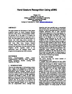
In this paper, a skin-colored region should be first detected from an input frame using the generalized statistical color model [4], and then the region including the hand is obtained by eliminating background using the distance transform (Figure 1-(a-d)). Note that in our method, this region (hereafter called the hand region) includes both the hand and a part of the forearm. Figure 1-(d) shows the detected hand region [5]. At this point, the hand (which excludes part of the forearm and include fingers and a palm as shown in the blue rectangle in Figure 1-(i)) can be segmented from the hand region using the following procedure (see also Figure 1).
INTRODUCTION
Hand (or hand posture) is one of the most frequently used and valuable part of human body for interaction. Thus, it has provoked interface researchers to consider the hand posture as a powerful interface for human-to-computer interaction. In this regard, recently, a number of hand posture recognition methods have been developed. Vision-based hand posture recognition methods can be classified into model-based methods [1] and modeless methods [2]. The model-based methods recognize the hand posture by comparing an input with a hand model. Those may allow more exact recognition for various postures but are unsuitable for the interfaces in real-time because those are based on complicated processes in many steps. The modeless methods commonly compare an input with posture data held at a database. Most of them work in real-time but cannot recognize various postures as exact as the model-based methods, because those are difficult to recognize postures excluded from the database. Also, the size of database increases in proportion to the number of recognizable postures and this may cause complex computation. This paper proposes a vision-based hand posture recognition method which does not require any database but can recognize various hand postures more sensitively by using shape decomposition. The shape decomposition methods commonly have complicated processes in many steps, so those are difficult to process in real-time [3]. However, we significantly reduce computation time of shape decomposition method by simplifying processes and transforming the hand into fixed form (a wrist is located at bottom of an image and fingers face upward). The proposed method detects a skin-colored region from an input frame using color model and distance transform, and segments a hand from the skin-colored region using prior knowledge for hand shape or geometry. As mentioned before, our method transforms the hand to a rectangle of a fixed size. The *email:
[email protected] †email:
[email protected] (corresponding author) IEEE International Symposium on Virtual Reality Innovation 2011 19-20 March, Singapore 978-1-4577-0037-8/11/$26.00 ©2011 IEEE
a. Find a mean direction of the hand region using least square line fitting of the points on the contour of the hand region. Compute the distances (hereafter called the distances of the hand region) between two points on the contour of the hand region orthogonal to the mean direction of the hand region (the contour of the hand region: Figure 1-(e), the mean direction of the hand region: a green line in Figure 1-(f), the distances of the hand region: Figure 1-(g)). b. Determine a location of the wrist by using the distances of the hand region which are computed in step a. Here, the location of the wrist is determined by the point where the distances of the hand region start to become constant as shown in a blue line between Figure 1-(f) and (g) (the location of the wrist: Figure 1-(h)). c. Finally, determine a hand using the mean direction of the hand region and a distance between two points where the contour of the hand region meets the line, which is orthogonal to the mean direction of the hand region and passes through the location of the wrist. The detected hand is shown in Figure 1-(i). The detected hand is transformed to the rectangle of a fixed size as shown in Figure 1-(j-l) and then the hand posture is recognized from the transformed hand using shape decomposition as shown in Figure 1-(m-o). Specific procedure for hand shape decomposition is described in chapter 3. 3
HAND POSTURE DECOMPOSITION
RECOGNITION
USING
SHAPE
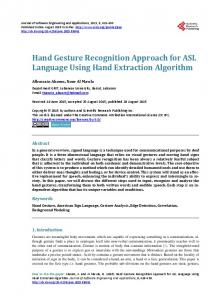
In this paper, the hand postures are recognized using the shape decomposition based on Morse theory [3]. First, our method counts the number of disconnection of the hand’s pixels on lines which are orthogonal to the line facing upward (red line in Figure 2-(b)), i.e. in Figure 2-(b), all pixels on the lines, which are orthogonal to the red line and under h1, are connected, thus the number of the under part of h1 is 0. Also, pixels on the lines, which are orthogonal to the red line and between h1 and h2, are disconnected once, thus their number is 1. Second, if the numbers of disconnection of upper and under parts are different, the hand is divided into upper and under parts. For example, in Figure 2-(b),
351
Figure 1. Overall workflow. (a) input frame, (b) skin-colored region, (c) distance transform, (d) hand region, (e) contour of the hand region, (f) mean direction of the hand region(green line), (g) distances of the hand region, (h) wrist, (i) detected hand, (j-l) transformed hand to the rectangle of fixed size, (m-o) detected fingers using shape decomposition.
the number of disconnection of upper and under parts of h1 is 0 and 1 respectively, thus the hand is divided into upper and under parts of h1. Figure 2-(b) is the result of division (here after called the hand segments). Finally, the hand segments are connected according to their relations which are calculated using the following procedure. a. Select and connect two segments from the hand segments. Determine a mean direction of the connected segment using the least square line fitting of the points on a contour of the connected segment. b. Find the mean points of the connected segment from the two points which are on a contour of the connected segment and meet a line orthogonal to the mean direction of the connected segment (the connected segment: two white segments in Figure 2-(c), the mean direction of the connected segment: the red line in Figure 2-(c), the line orthogonal to the mean direction of the connected segment: the green line in Figure 2-(c), the mean points of the connected segment: the black points in Figure 2-(c)). c. Do following procedure to the mean point found in step a. c-1. Determine the local directions of the mean points using the least square line fitting. c-2. Calculate the widths which are distances between two points which are on the contour of the connected segment and meet a line orthogonal to the local direction of the mean points. d. If there is the section that the widths are rapidly changed, divide the connected segment into primary segments. e. Repeat step a-c for all segments.
Figure 2. Hand shape decomposition. (a) Hand, (b) hand segments, (c) relation of two segments calculation, (d) hand segments connected by their relations, (e-f) fingers detection.
4
ACKNOWLEDGEMENTS This work was supported by the Technology Innovation program of MKE. [KI001802, Development of Vision/Image Guided System for Tele-Surgical Robot] REFERENCES [1]
[2]
Figure 2-(d) shows the result of above procedure. As shown in Figure 2-(e), the fingers are determined by detecting long and thin segments among the hand segments connected using above procedure. The proposed method decides the hand posture using information of the detected fingers, e.g. the length of the detected fingers. Figure 2-(e) shows result of the hand shape decomposition with all fingers slightly bent and Figure 2-(f) shows the hand with three fingers fully extended and the other fingers bent. As shown in Figure 2-(e) and (f), the fingers fully extended are longer than the fingers slightly bent. Also, the fingers bent are not detected.
352
CONCLUSION
In this paper, the hand posture recognition method was proposed. The proposed method can recognize tiny motion changes of fingers without huge database by using the shape decomposition. We expect that the proposed method is extended toward implementing various interfaces.
[3] [4]
[5]
S. Lu, D. Metaxas, D. Samaras, and J. Oliensis. Using Multiple Cues for Hand Tracking and Model Refinement. Proceedings of CVPR’03, volume 2, pages 443-450. 2003. R. Lockton and A. Fitzgibbon. Real-time Gesture Recognition Using Deterministic Boosting. Proceedings of BMVC’02, pages 817-826. 2002. H. Liu, W. Liu, and L. J. Latecki. Convex Shape Decomposition. Proceedings of CVPR’10, pages 97. 2010. M. J. Jones and J. M. Rehg. Statistical Color Models with Application to Skin Detection. Proceedings of CVPR’99. volume 1. 1999. Junyeong Choi, Byung-Kuk Seo, and Jong-Il Park. Robust Hand Detection for Augmented Reality Interface. Proceedings of VRCAI’09, pages 319-322. 2009.