HANDLING OF VIRTUAL CONTACT IN IMMERSIVE VIRTUAL ENVIRONMENTS: BEYOND VISUALS Robert W. Lindeman1, James N. Templeman2, John L. Sibert1 and Justin R. Cutler1 1
2
Dept. of Computer Science The George Washington University 801 22nd St., NW Washington, DC 20052 USA {gogo | sibert | jrcutler}@gwu.edu
CODE 5513 Naval Research Laboratory 4555 Overlook Ave, SW Washington, DC 20375 USA
[email protected]
ABSTRACT This paper addresses the issue of improving the perception of contact that users make with purely virtual objects in virtual environments. Because these objects have no physical component, the user's perceptual understanding of the material properties of the object, and of the nature of the contact, is hindered, often limited solely to visual feedback. Many techniques for providing haptic feedback to compensate for the lack of touch in virtual environments have been proposed. These systems have increased our understanding of the nature of how humans perceive contact. However, providing effective, general-purpose haptic feedback solutions has proven elusive. We propose a more-holistic approach, incorporating feedback to several modalities in concert. This paper describes a prototype system we have developed for delivering vibrotactile feedback to the user. The system provides a low-cost, distributed, portable solution for incorporating vibrotactile feedback into various types of systems. We discuss different parameters that can be manipulated in order to provide different sensations, propose ways in which this feedback can be combined with feedback of other modalities to create a better understanding of virtual contact, and describe possible applications. KEY WORDS: haptic feedback; multimodal interaction; vibrotactile feedback
1
1. INTRODUCTION Virtual contact research addresses the problem of what feedback to provide when the user comes into contact with a purely virtual object within a virtual environment (VE). Current technology limits our ability to provide as rich an environment as we experience in the real world. Therefore, it is of interest to us to help define the subset of feedback for these environments that will maintain or improve human performance, and to find ways of effectively presenting the stimuli, thereby allowing the higher-level cognitive systems to construct a reality that, though of a lower fidelity, still produces an equivalent experience. As humans, we interact with our environment using multiple feedback channels, all coordinated to help us make sense of the world around us. The limited multimodal feedback in current VE systems, however, hinders users from fully understanding the nature of contacts between the user and objects in these environments. It has been found that because real-world contact combines feedback spanning multiple channels (e.g., tactile and visual), providing feedback to multiple channels in VEs can improve user performance [1,2]. Grasping virtual controls, opening virtual doors, and using a probe to explore a volumetric data set can all be made more effective by providing additional, multimodal feedback. In essence, we are addressing the need for supporting effective user actions in environments with reduced sensory feedback, because the only feedback the user receives is that which we provide. Current approaches to providing haptic feedback, described in more detail below, typically use force-reflecting devices, such as the PHANToM, or exoskeletons. These devices can provide very effective feedback, but their use is limited by their expense and cumber. Our current focus in this area is on developing a mobile, extensible system for delivering vibrotactile feedback to multiple parts of the body using a single device controller. The vibrotactile elements (tactors) are positioned at different points on the body, and controlled from a proximal control unit. Multiple units can be linked together and controlled either from 2
a handheld computer carried on the person, or from a remote host using a wireless connection. Our use of vibrotactile feedback is built on previous work in the use of passive props, and represents an evolutionary step towards the ultimate goal of providing a highfidelity experience to users of VR. 2. PREVIOUS WORK Next we review previous work on providing feedback to the different sensory channels, with particular focus on the haptic channel. 2.1 The Sensory Channels Although it is the visual sense that has received the most attention from VE researchers, some work has been done on feeding the other senses. After visuals, the auditory sense has received the most attention [3,4,5]. The proprioceptive sense has also received some attention [6]. The senses of smell and taste have received less attention, possibly because of the difficulty and intrusiveness involved in delivering a wide range of stimuli [7]. The area of haptics has received increasing attention from VE researchers over the past decade. A common finding of researchers in these different sensing modalities is that it is not enough to address only one of the senses; that to give a deeper feeling of immersion, multiple senses need to be stimulated simultaneously, and in a coordinated fashion. Furthermore, providing more than one type of stimulus allows researchers to achieve acceptable results using lower "resolution" displays [8]. This becomes important for low-cost applications, like game consoles or aids for the hearing impaired [9], or in applications with potential transmission delays, such as on-line conferencing or gaming. For example, it is possible that relatively simple haptic feedback when combined with high-quality visual images, which have become very inexpensive to produce, could create a similar sense of contact produced by moreexpensive haptic displays alone. Further work is needed to quantify this.
3
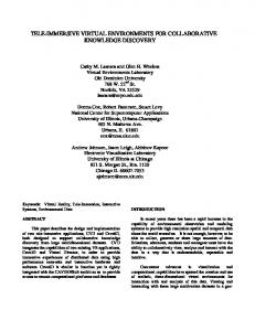
2.2 The Human Haptic System Describing the physical elements and cognitive processes involved in how we perceive and process the sense of touch has proven to be a difficult task [10]. Loomis and Lederman [11] define two main tactual modes by the amount of control the user has over the exploration of the touched surface. We choose here to follow the categorization used in much of the perception literature [11,12]. Broadly, the human haptic system can be broken down into two major subsystems. The tactile subsystem refers to the sense of contact with an object, and receives information mediated by the response of mechanoreceptors in the skin within and around the contact area. Experiments have been performed defining the characteristics and thresholds of the different mechanoreceptors [8,1]. The kinesthetic/proprioceptive subsystem (referred to as the kinesthetic system here) allows the nervous system to monitor the position and motion of limbs, along with the associated forces, and to receive information from sensory receptors in the skin around the joints, joint capsules, tendons, and muscles, as well as from motor-command signals [8]. The tactile and kinesthetic systems play roles of varying influence depending on the task we are performing. If we arrange their influence as axes on a graph, we can define a space for plotting tasks we perform in VEs as shown in Figure 1.
Surface Texture Exploration
Moving a Finger Through a Viscous Substance
Influence of Tactile System
Tool-Mitigated Manipulation Pressing a Physical Button Direct Object Manipulation Non-Contact Arm Movements
Influence of Kinesthetic System
Figure 1: Influence of Tactile System vs. Influence of Kinesthetic System
4
It is clear that obtaining an accurate understanding of the haptic system requires more than simply studying the tactile and kinesthetic systems in isolation. Gibson formulates this notion by stating that to "lump one set of receptive systems together as touch and another as kinesthesis, then, is to obscure the function of the systems in combination" [10, p.484]. He goes on to argue that sensing is different if we are passively being touched, e.g., a probe is poked into the finger pad, versus actively touching, e.g., exploring the probe with the finger pad. Taking this notion into account could have a major influence on how we design interfaces that incorporate the haptic sense. Another view is taken by Srinivasan [8] who uses the terms exploration and manipulation to describe a framework for studying biomedical, sensory, motor, and cognitive subsystems. The process of exploration is mainly concerned with extracting attributes of objects, and is therefore a tactile-dominated task. Manipulation is mainly concerned with modifying the environment, and is therefore dominated by kinesthetic feedback. Indeed, both subsystems play a role in almost every type of interaction; it is the strength of their influence that varies. In terms of producing haptic feedback, passive approaches use properties inherent in physical props to convey stimuli [13,2]. These systems do not require any computer control to provide a stimulus, and can provide high-fidelity, inexpensive (both computationally and monetarily) feedback. An example of this would be to register a physical railing with the representation of a railing in a VE, allowing the user to feel the real railing when reaching for the virtual one [14]. Props can be instrumented with sensors to make them into input devices [13]. Because these objects are passive, however, the range of feedback any given object can provide is limited in both type and strength. Therefore, a more flexible approach to stimulating the haptic sense is through the use of active-haptic feedback [15]. These approaches typically
5
deliver stimuli using some sort of force-reflecting device, such as an arm-linkage employing sensors and actuators [16,17], force-feedback gloves [18], or master manipulators [19]. Much of the empirical work into determining how we sense touch has focused on the hands, and, in particular, on the finger pad of the index finger [20]. Some approaches combine tactile and kinesthetic stimulation into a single system. Howe [17] describes a teleoperation system for supporting a precision pinch grasp, using a two-fingered linkage. Wellman and Howe [21] augmented this device by attaching inverted speakers, controlled by output from a PC sound card, to each of the master finger brackets, thereby adding a vibratory component to the feedback system. Kontarinis et al. [22] describe the addition of arrays of shape memory alloy (SMA) wire actuators to this system for providing feedback directly to the finger pad. Howe et al. [23] describe methods for improving the responsiveness of SMA actuators by producing faster heating response using feed-forward derivative compensation, faster cooling response using pneumatic cooling jets, and reduced hysteresis through the use of position-sensing LEDs. Some researchers have conducted studies using SMA arrays [24,20]. In addition to SMA, other materials can also be used for tactile stimulation (see [25] for a comparison of material properties). Some researchers have focused on our ability to discern combinations of sinusoidal waveforms at differing frequencies [9,26,24]. Others have looked at our ability to discern patterns in the presence of temporal masking of pattern elements [20]. In teleoperation experiments, researchers have looked at how vibratory feedback can be used to regulate the amount of pressure applied at the slave side [27]. Some researchers have begun to explore the use of vibrating motors, similar to those used in pagers and cell phones, as a means of providing inexpensive haptic feedback [28,29,30]. Hughes and Forrest [12] instrumented a standard desktop mouse with vibration elements and
6
discuss its application to multivariate map exploration. We propose combining low-cost vibrotactile (VT) feedback units with feedback through other channels to relay contact or other information to the user. In the absence of actual, physical walls, tactors mounted on the user (e.g., on the arm) could be triggered to simulate physical contact between the arm and a virtual wall. It is hoped that this integration of VT feedback into a VE system would thereby improve a user's sense of contact made with objects in the VE. Commercial products have also emerged, both in the home-entertainment and research areas. Simple vibrotactile attachments for game console controllers have been commercially available for some time now. Sony, Nintendo, and Microsoft all produce devices utilizing eccentric motors to add vibration to the gaming experience. Consumer-grade force-feedback joysticks from Microsoft and Logitech, and commercial-grade force-feedback joysticks from Immersion Corporation [31] use actuators to control the resistance/force delivered to the handle of the controller. Virtual Technologies, Inc., produces a glove instrumented with six VT units, five on the fingers and one on the palm. This is a representative, rather than exhaustive, list of commercial force-feedback offerings, and underscores the attention currently being paid to the use of VT feedback by industry. 2.3 Research Questions We see several important steps within VT feedback research where more work is required, and posit them as fertile areas of short- to medium-term research. These include: 1. Methodical studies of the parameter sensitivity of VT feedback, across devices, users, applications, etc., 2. A framework for combining VT with other feedback modalities, and 3. Exploration of application areas (tasks) where this holistic feedback could be effective.
7
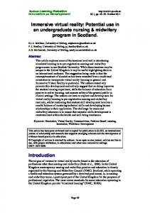
Currently, we are concentrating our efforts on designing a testbed for comparing different types and amounts of multimodal feedback. This will allow us to address some of these issues. 3. CURRENT PROTOTYPE We have built a prototype VT feedback system using a proprietary control circuit (Figure 2) and commercial, off-the-shelf tactors. The TactaBoard is based on a Microchip PIC 16F87320 microcontroller. It is clocked at 20 MHz, supports 2 kilobytes of program memory (used to store the program and default values), 128 bytes of EEPROM (non-volatile memory used to store configuration values for the board), and 192 bytes of RAM. Support circuitry includes a Maxim MAX233CPP serial interface chip, and one transistor per tactor for switching the tactor supply voltage.
Tactor Connectors
Output Transistors
PIC Microcontroller
Maxim MAX233CPP
Upstream TactaBus Connector
Downstream TactaBus Connector
Figure 2: TactaBoard Prototype Each TactaBoard is a self-contained unit for controlling 16 tactors, and communicates with the host computer using an RS-232 serial connection. Additional TactaBoards can be connected to the first board using a proprietary TactaBus connection. Each TactaBoard has connectors for the tactors, power, and the TactaBus cables. The high-level layout of a system with multiple TactaBoards is shown in Figure 3.
8
Serial Line
TactaBus
Host Computer
TactaBoard
Cable to Tactor TactaBoard
...
TactaBoard
Figure 3: Multiple TactaBoards The tactors we are using are the vibration motors found in most cell phones or pagers. They use an eccentric mass attached to the shaft of a DC motor to provide vibration. Varying the voltage changes the spin rate, thereby changing the vibration. By placing the tactors at strategic locations on the body, and triggering them appropriately, we can provide a sense of contact. 3.1 Design Goals VR has not lived up to its initial hype, and we feel one reason for this is the lack of adequate feedback to allow users to perform precise tasks effectively. Providing better support for object manipulation should improve this situation. The TactaBoard system has been designed with certain characteristics in mind. These include: Energy Efficiency: Pulse-Width Modulation (PWM) allows for less power to be consumed, compared to constantly feeding analog signals to the tactors. Flexibility:
Different types of tactors can be controlled using a single system. In addition, each board can either receive its power from the TactaBus, or external power can be provided through the on-board power connector. Also, each TactaBoard can operate at a different update frequency.
Scalability:
Each TactaBoard can support up to 16 tactors, and up to 255 TactaBoards can be connected on a single TactaBus.
Mobility:
The system can use a wireless modem, connected directly to the TactaBoard, to communicate with a host. Alternatively, combined with a handheld computer, the system can run completely autonomously.
9
Distributability:
Each TactaBoard refreshes its 16 tactors independently of the other TactaBoards, thereby increasing the overall update capacity of the system.
Compactness:
Each TactaBoard is about the size of a handheld computer (i.e., PDA).
Expense:
We have used mainstream electronic components for our design, reducing the cost of the parts.
Simplicity:
A minimum number of components has been incorporated into the design, thereby reducing the complexity of assembly.
Updateability:
The firmware on each TactaBoard can be updated using an in-socket updating process.
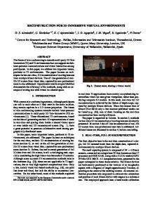
In addition to VE applications, these characteristics make this system well suited for a variety of other application areas described later. 3.2 Pulse-Width Modulation A main concept used by the TactaBoard is Pulse-Width Modulation (PWM) [32]. This is similar in nature to the way commercial "dimmer switches" work. The idea is to vary the amount of time voltage is sent to a device, rather than varying the level of voltage that is sent. This means that PWM devices can be installed into existing electrical systems without the need for varying the power being supplied to the system. As an example, Figure 4 shows a comparison of how to reduce an output voltage from 50% of to 25% by decreasing the input voltage (a) and by decreasing the duty cycle of a PWM signal (b). As an example, if a light bulb requires 9 volts in order to achieve maximum illumination, we can achieve half of the illumination by reducing the input voltage to 4.5 volts, or by sending the 9 volt input to the bulb 50% of the time at some frequency. Maintaining a sufficient frequency eliminates the apparent flicker of the bulb.
10
V 100% o l t 50% a 0% g e
Period
Period
V 100% o l 50% t a g 0% e
time
Period
(a)
Period
time (b)
Figure 4: Varying the Output: The resulting output produced by halving the input voltage (a) can be achieved by halving the ON time (duty cycle) within a pulse period (b). Proprietary firmware we have written, running on each TactaBoard, performs the generation of a separate PWM signal for each tactor connected to the TactaBoard. This firmware updates the PWM signal for each tactor while handling requests from the host computer as they arrive on the TactaBus. A signal frequency ranging from 0.3 Hz to 316 Hz can be generated. The period can vary from 3.16 milliseconds to 3.3 seconds, and the switching resolution (i.e., the resolution of the duty cycle) can be computed as the period divided by 256, which results in a range from 12.4 microseconds to 13 milliseconds. The required update rate described in studies found in the literature, 10-250 Hz [1,11], is within the range supported by the TactaBoard. The frequencies in the literature are reported primarily for the finger pad. Studies will have to be done to measure sensitivity at other body locations. 3.3 Software API The low-level protocol uses standard serial output and a byte stream for commands. On top of this, we have developed an Application Programming Interface (API) for programs on the host computer to control the devices using the TactaBoard system. We have developed APIs for C/C++ and Tcl/Tk, with Java support currently under development. Extending support to additional languages or other hosts, such as handheld computers, is straightforward. Using a connection-oriented approach, the API allows the application to control the output level of each individual tactor by passing a board-ID, tactor-ID, and target level. Each of these 11
parameters is one byte in size. Passing a value of 255 for the board-ID broadcasts the command to all boards for the tactor specified by tactor-ID, and passing a value of 255 as the tactor-ID broadcasts the command to all tactors on the board specified by board-ID. Figure 5 shows a code example for generating a sine wave for a single tactor.
// sinetest.cpp // Test of TactaBoard API // Set Output 0 on Board 0 to // the output of the sine function. #include #include #include "tactaboard.h" const unsigned char BOARD_ID = 0; const unsigned char OUTPUT_ID = 0; int main( int argc, char* argv[] ) { TactaBoard tb; // Instance of a TactaBoard object. doubl e x = 4.71; // Make first value start at 0. unsigned char v; // Value to set the output to. tb.open( "COM1" );
// Open the serial port.
for( int i = 0; i < 1000; i++ ) { // Value: 0