Preprints of the 18th IFAC World Congress Milano (Italy) August 28 - September 2, 2011
Haptic-based navigation for the virtual bronchoscopy ⋆ Paolo Cabras ∗ Jan Rosell ∗ Alexander P´ erez ∗,∗∗ Wilbert G. Aguilar ∗ Antoni Rosell ∗∗∗ ∗
Institute of Industrial and Control Engineering - Technical University of Catalonia, Barcelona, Spain (e-mail:
[email protected]). ∗∗ Esc. Colombiana de Ingenier´ıa “Julio Garavito”, Bogot´ a, Colombia ∗∗∗ Servei de Pneumologia, Direcci´ o Cl´ınica de Malalties Respirat` ories, Grup de Recerca Pneumol` ogica-IDIBELL, Hospital Universitari de Bellvitge, Barcelona, Spain
Abstract: In order to help in the diagnosis of peripheral lung lesions, this paper presents a virtual bronchoscopy system that allows the navigation within a 3D reconstruction of the tracheobronchial tree using a haptic device whose permitted motions mimics those done with the real bronchoscope, and that is able to feedback forces resulting from contacts with the walls. The system reconstructs the 3D model from CT images, and computes a path from the trachea to the peripheral target to be analyzed in order to guide the exploration. The execution of the virtual bronchoscopy with the proposed system, prior to the execution of the real one, may increase the confidence of pulmonologists and is expected to result in an improvement in the final lung cancer diagnosis. Keywords: Biomedical systems, Virtual reality, Device simulation, Bronchoscopy, Lung cancer. 1. INTRODUCTION Bronchoscopy is an interventional medical procedure used to analyze the tracheobronchial tree, mainly to obtain samples from a specific lung site identified by chest X-ray computed tomography (CT), mainly for the diagnosis of lung cancer. A critical point of this technique is obtaining the right path to the target when the lesion is located in a peripheral zone. This path is usually planned from the 2D CT images, which is difficult and error prone, resulting in an extended execution time of the bronchoscopy due to trial and error movements to reach the target. The finding of the path can be improved if bronchoscopy is performed under fluoroscopy (a real-time moving image of plain chest X-ray), although then operators are at risk of ionizating radiation. To cope with this problem and trying to minimize invasive medical procedures as much as possible, Virtual Bronchoscopy (VB) has emerged as a useful tool. VB is a computer-generated 3D reconstruction technique that allows medical staff to explore the tracheobronchial tree to make a previous analysis of the lungs: although it does not allow to see the real colors of the lumen nor any possible lesions, it helps locating the diseased zone, evaluate whether it is necessary to proceed with the real bronchoscopy and automatically plan a path within the 3D model. VB has been applied with different purposes. One example uses the data contained in the 3D image to localize where the mediastinal lymph node is, within the tracheobronchial ⋆ Work partially supported by Spanish Government projects FIS PI09/90088, FIS PI09/90917, DPI2008-02448, DPI2010-15446.
Copyright by the International Federation of Automatic Control (IFAC)
tree (Ferguson and McLennan, 2005), (McAdams et al., 1995). In conventional bronchoscopy, pulmonologists can only see the airway lumen and not on the other side of its nontransparent bronchial epithelium, where the lymph node (that is the target for a transbronchial needle aspiration or core biopsy) may be. By image processing, the virtual bronchial tube can be made transparent and so make the lymph node visible. Comparing, then, the virtual and the real images or superimposing them, physicians can reach, from within the airway, the external lymph node with a great degree of confidence. A second advanced virtual bronchoscopic application is that of path-finding to a peripheral region of interest within the lung (Kiraly et al., 2004). Thanks to the high quality 3D reconstruction of the airway available nowadays, specialized software can find the path that joins the trachea with the peripheral diseased zone. This path can be easily cannulated and once this tube is placed, several probes can be placed either to brush, to perform a biopsy or wash the lesion of interest. The last interesting application involves the targeting of peripheral lung for the so-called endobronchial lung volume reduction. The information that is required is the state of the lung parenchyma and the extent of emphysema in each segmental region, together with the anatomic configuration and size of the subtending airway segments. This eases the planning of several issues, such as valves dimensions, before preforming the procedure (Snell et al., 2003). Complementarily to VB, a training tool for the bronchoscopy has been developed, called bronchoscopy simulator (Satava, 2004),(Colt et al., 2001). It is a virtual reality simulator with a model of a flexible bronchoscope and patient that makes the pulmonologist in training to
9638
Preprints of the 18th IFAC World Congress Milano (Italy) August 28 - September 2, 2011
feel like he/she was performing a real bronchoscopy (CAE, 2010). A bronchoscopy simulator allows users to repeat the procedural experiences at their own pace and practice medical procedures by accurately duplicating the look and the feel of real-life situations. This improves patient safety by allowing physicians to be more experienced by practicing more without putting patients at risk. Moreover, it also improves initial training in terms of time-efficiency and cost-effectiveness. In a very short period of time, fellow physicians can be exposed to a broad range of cases that reflect variations in patient anatomy, pathology and physiology, receiving instant feedback from the simulator which measures participant performance (Wahidi et al., 2010). These exercises or procedures would otherwise require numerous real-life encounters and costly hours of supervision.
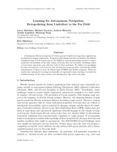
CT Images
3D Reconstruction
Visualization
3D Model
Planning
Guiding
1.1 Motivation
Navigation
Haptic
VB is a very useful tool for non-invasive bronchial analysis and preoperative planning of real bronchoscopy. However, It only provides an exploration made by a camera flight passing through pre-established points, or controlled with the keyboard or mouse. Therefore, it does not allow any sort of interaction with the airways, nor a correspondence with the real movements the physician would do with the real bronchoscope. Furthermore, since no interaction is provided, the “virtual camera” can go out of the tracheobronchial tree, while exploring within.
Device
Fig. 1. Modules involved in the haptic guided VB system The system is composed of the following modules (Fig. 1): (1) 3D reconstruction module: It is responsible of generating a triangular mesh to represent the 3D model of the tracheobronchial tree from a stack of CT images. (2) Planning module: It is responsible of finding a path for the bronchoscope to navigate from the trachea to the peripheral zone that is to be explored, taking into account the motion constraints a bronchoscope has. (3) Visualization module: It is responsible of the visualization of the 3D model of the reconstructed tracheobronchial tree, both from an inside and outside view, and of the proposed path found by the planning module. (4) Navigation module: It is the responsible of the control of the haptic device that allows the navigation through the tracheobronchial tree, mimicking as much as possible the motions done with a real bronchoscope. (5) Guiding module: It is responsible of giving the users hints on how to move the haptic device to follow a suggested path, both using the force feedback a haptic device provides, and using graphical indications.
Bronchoscopy simulators, on the other hand, provide a very realistic environment (considering force feeling, procedure and instruments), but are constrained to few preset variations in patient anatomy, pathology, and physiology. While they are very useful training tools, they do not allow the virtual exploration of real patients. Therefore, there is the need to improve VB to make lung exploration as realistic as possible, as if physicians were really handling a bronchoscope. This paper makes a proposal based on the use of a haptic device, which is a device that allows force feedback, that can be exploited to give the sensation of touch and interaction with the real physical bronchial tube. 1.2 Approach overview With the aim previously stated, this paper proposes a VB system with the following main features: • The input is a stack of CT images from which a 3D model of the tracheobronchial tree is obtained. • A path from the trachea to the peripheral zone to be explored is computed and visualized within the 3D model of the tracheobronchial tree, serving as a guide for the exploration. • The user can navigate using a haptic device by manipulating the stylus of the device in a similar way as he/she does when manipulating the real bronchoscope. • The user may feel forces resulting from the contacts between the tip of the virtual bronchoscope and the 3D model of the tracheobronchial tree. • The system has the capability to backtrack the path navigated, thus helping the user in the exploration.
Haptic Rendering Engine
The system works as follows. Once the 3D model of the tracheobronchial tree is reconstructed, the planning module computes a path from the trachea to the peripheral zone marked as a target. Then the user can navigate within the model using the haptic device, manipulating the haptic device handle as if it was the bronchoscope. During navigation, the haptic rendering algorithm feedback forces coming from virtual contacts between the tip of the virtual bronchoscope and the 3D model of the tracheobronchial tree, and guiding forces that try to keep the user along the calculated solution path. The user has also visual information both as seen from the camera at the tip of the virtual bronchoscope and outside the tracheobronchial tree. The paper describes all the system modules (although the emphasis is on the navigation module), and is structured as follows. Section 2 explains how the task is modeled, i.e. the 3D reconstruction module, as well as the way
9639
Preprints of the 18th IFAC World Congress Milano (Italy) August 28 - September 2, 2011
Fig. 2. A typical CT image, showing a transverse section of the lung. the bronchoscope is modeled in order to plan its path within the tracheobronchial tree. Section 3 introduces the haptic device, the way it is controlled in order to mimic the user motions manipulating a bronchoscope, and the rendering of virtual forces. Section 4 then presents the rapidly-exploring random trees which is a path planning method used in robotics for the planning of paths for robots with kinematics constraints and explains how it is customized for the task at hand. Finally, Section 5 discusses some visualization issues and Section 6 summarizes the contributions and concludes the work. 2. TASK MODELING
2
3 1
Optic Fiber
A B
C
flexible tip
A
Fig. 4. Degrees of freedom of a bronchoscope.
2.1 The tracheobronchial tree Computed tomography scanners obtain 3D data as a stack of 2D images, as shown in Fig. 2. For virtual bronchoscopy navigation, a triangular mesh representing the 3D model of the tracheobronchial tree is required (Fig. 3), which has to be obtained with segmentation procedures, like the works of Kiraly et al. (2002) and Aykac et al. (2003). In this project gray-scale morphological reconstruction is used. The process can be sketched by the following steps: (1) Edge-preserving filtering: This step smoothes out the difference between gray levels of neighboring voxels with a diffusion process that is reduced or stopped in the vicinity of edges, thus preserving them. (2) Thresholding and masking: This step first obtains a binary image using a threshold of -900 HU 1 , then labels the resulting regions and filters out those below a given volume, and finally binarizes and dilates the result and uses it to mask the original data. (3) Gray-scale reconstruction: This step performs a dual numerical reconstruction of the masked image from a gray-level marker image, resulting in an output image with more homogeneous valleys. (4) Surface generation: Using the reconstructed image, this last step generates a three-dimensional triangular mesh that wraps the voxels below a given threshold. The 3D reconstruction module is implemented using the software AMIRA (2010) that reads CT images, allows image processing using many segmentation tools including morphological filters, and has surface generation capabilities to reconstruct the 3D model as a triangular mesh and export it as a VRML file 2 . Currently CT slices 0.6mm 1
Fig. 3. 3D reconstruction of a tracheobronchial tree.
Hounsfield Units is a scale that measures the radiodensity and has a value of -1000 for the air. 2 VRML is a standard file format for representing 3D interactive vector graphics (Ames et al., 1997).
thick are employed, being the size of the smallest bronchia segmented of the 3rd order, with an approximate diameter of 3.30mm. 2.2 The bronchoscope There are two ways to perform a bronchoscopy, depending on whether the bronchoscope used is a rigid bronchoscope or a flexible bronchoscope. The technique mostly used nowadays is the flexible bronchoscopy for the consequent improved patient comfort and reduced use of general anesthesia. To look inside the airway, this procedure uses a CCD camera mounted at the tip of the flexible bronchsocope (videobronchsocope). Nowadays, traditional fiberoptic bronchoscopes are seldom used. The motions of the bronchoscope are coupled, i.e. its kinematics is constrained, and can be described by the following three degrees of freedom (DOF) illustrated in Fig. 4: (1) Translational forward/backward motion of the tube along the A-axis performed by pushing and pulling the bronchoscope. (2) Rotational motion around the A-axis produced by the rotation of the whole bronchoscope handle. (3) Rotational motion of the tip around the C-axis (±90◦ ) obtained by turning a wheel (the camera central axis, B, coincides with A when the wheel is at its home position). The model of the bronchoscope tube can be approximated by a kinematic chain composed of a set of n cylindrical links of the same length as shown schematically in Fig. 5 for n = 4 (the more the links are, the more reliable the approximation will be). With this perspective, the bronchoscope is like a robot which has the camera in its
9640
Preprints of the 18th IFAC World Congress Milano (Italy) August 28 - September 2, 2011
TCP 3 (looking towards the −Zt -direction with the Yt -axis pointing upwards). Yt T CP ξ Zt X t
∆α Z
ZW
ξ
YW Y (n − 1)ξ XW ≡X ∆z
ξ Fig. 6. Phantom Omni with the axes of movement. r l
d
ξ
Yc
the hardware controller (driver) sends the translation information to the software simulator, which determines if a reaction force is required and its magnitude value. The host computer sends feedback forces to the device actuating on the joint motors.
∆β
Xc C Zc
Yb Xb r ∆α Zb Fig. 5. Model of the bronchoscope for n = 4.
3.2 Motion control
With this model, the bronchoscope DOF can be described as follows: • Pushing/pulling the bronchoscope an increment ∆z corresponds to a rectilinear translational motion along the Zb -axis if the tip is totally extended (i.e. ξ = 0). Otherwise, it corresponds to a negative rotation of an angle ∆β about the XC -axis: ∆z 2∆z sin(ξ/2) ∆β = = d l cos(ξ/2) • A rotation ∆α done with the bronchoscope handle (about the A-axis in Fig. 4) corresponds to a rotation around the Zb -axis (it coincides with a rotation about the camera Zt -axis only if the tip is totally extended). • A rotation of the bronchoscope wheel corresponds to a change in the value ξ of the the joint angles. Since all the joints are coupled, the total bending angle of the tip is (n − 1)ξ.
To explore the virtual scene the movement of the camera has to be controlled. Since the camera is mounted on the tip of the bronchoscope, the problem is to control the motion of the tip of the kinematic chain that models the bronchoscope. To make the navigation with the haptic device as realistic as possible, the control of each of the DOF of the bronchoscope is done as follows: • The pushing/pulling movement is performed by a movement along the device YW -axis. The y component of the device position gives the linear increment ∆z. A negative increment corresponds to the pushing movement. • The rotation ∆α around the A-axis is performed by a rotation of the 6th joint. • The rotational motion of the tip around the C-axis is performed by a rotation of the 5th joint that increases/decreases ξ, moving the camera up or down.
3. NAVIGATION USING A HAPTIC DEVICE 3.1 Haptic device Haptic devices (or haptical interfaces) are mechanical devices that allow users to touch, feel and manipulate 3D objects in a virtual environment or in a tele-operated system. They are input-output devices, meaning that they track a user’s physical manipulations (input) and provide realistic touch and sensations coordinated with onscreen events (output). Haptic feedback means both tactile and force feedback: tactile feedback allows users to feel things such as the texture of surfaces and vibration, force feedback reproduces directional forces that can result from solid boundaries, the weight of grasped virtual objects, mechanical compliance of an object and inertia. The device used in this work is a Phantom Omni (Fig. 6), that can be classified as a “linkage-based” system, which consists of a robotic arm attached to a stylus. The arm tracks the position of the stylus and is capable of exerting a force on the tip of this stylus. To exert force it uses an impedance control algorithm: the position sensors detect the movement made with the device by the user, then 3
Tool Center Point, the tip of the last link of the robot.
The other DOF of the device are not considered and in the case of the translation along the X-axis, the device is constrained to the origin to render the fact that the bronchoscope cannot move on the plane perpendicular to its longitudinal axis (A-axis), once it is inserted in the airway. In order to continually maintain these connections between the haptic device and the virtual bronchoscope, every clock cycle ∆z, ∆α and ∆β are recalculated. With these values the movement of the base (Tbasei ) is calculated (Fig. 7) 4 : −1 Tbasei = Tbasei−1 ·T(Zb ,∆α) ·T(0,−d,− l ) ·T(XC ,∆β) ·T(0,−d,− l ) 2
2
Once the new positioning of the base (Xb′ , Yb′ , Zb′ ) is known, the transform matrix relating the camera frame (Xt′ , Yt′ , Zt′ ) with the world frame is calculated: Tcamera = Tbase · T(0,−d,− l ) · T(XC ,−(n−1)ξ) · T(0,d,− l ) 2
2
When the pulmonologist is pulling the device out of the airways, the tip will inevitably go for the same path it went during the forward movement. To also implement this characteristic, during the forward translation the camera 4
T(x,y,z) is a translation described by the vector (x, y, z) and T(X,α) is a rotation about the X-axis of an angle α.
9641
Preprints of the 18th IFAC World Congress Milano (Italy) August 28 - September 2, 2011
Z′ Zt
Yt
Xt
Zt′
l/2
Yt′
Xt′
Yb′ Yc′ Yc
d
l
Yb Xb
Path planning is a quite researched field in robotics, being nowadays the sampling-based methods able to successfully solve problems for robots with many degrees of freedom, in cluttered environments and taking into account kinematic constrains. Basically this kind of methods randomly generate collision-free samples of configuration space and connect them with free paths capturing the connectivity of the free space by forming either roadmaps (called Probabilistic Roadmaps PRMs (Kavraki et al., 1996)) or trees (called Rapidly-exploring Random Trees RRTs (LaValle and Kuffner, 1999)).
TCP’
d
′ Zb′ Xb
B
4. PATH PLANNING
TCP
r
Zb ∆z
C
Xc ∆β ′ Zc Zc
≡ Xc′
Fig. 7. Effect of ∆z forward movement on the modeled bronchoscope tip (from TCP to TCP’). position and orientation are memorized to be used when the user starts a backward navigation, by moving the stylus in a position having a positive y component.
3.3 Haptic rendering The haptic renderer’s task is to compute the correct interaction between the representation of the haptic interface in the virtual environment and the objects populating that environment. Three sets of algorithms are required (Salisbury et al., 2004): collision-detection algorithms to detect collision between the avatar and the objects, yielding information about where, when, and ideally to what extent collisions (penetrations, indentations, contact areas, and so on) have occurred; force-response algorithms to calculate the reaction forces when collisions occurs and control algorithms to assure a reliable transformation from ideal forces (calculated by force-response algorithms) to applicable forces so as to correctly render such forces on the human operator through the device. When a bronchoscopy is carried out, all the forces are basically felt along the tube longitudinal axis which is pushed down. So, in the case a wall was hit, the force felt would be along the mentioned axis. This is reproduced by sending a force in the device +YW -axis , every time a collision is detected. The main problem when treating with thin walls as those of the bronchial model is the so-called “falling-through”: when hitting the wall the proxy can cross the wall itself and, in this case, go out from within the airways. GodObject haptic rendering presented by Zilles and Salisbury (1995) resolves, somehow, this problem even though it still presents falling-through when the probe slides on acute concave intersection of surfaces. As a first approximation in the case studied here, this imprecision can be acceptable since the tracheobronchial tree surface rarely presents acute intersections of surfaces and also because when the bronchoscope tip hits the wall it is immediately pushed back avoiding the sliding as much as possible. The possibility of falling through depends on the quality of the reconstruction (i.e. how smoothly the triangle faces of the 3D model are connected so as to avoid acute intersections) and also on the collision velocity (the slower the better).
4.1 The Rapidly-Exploring Random Trees An RRT starts a tree rooted at an initial configuration and is grown towards randomly generated samples until the goal configuration is reached. The growth is performed as follows. Once a random configuration c is sampled, the nearest leaf on the tree is selected and a branch is grown, during a time interval, towards c in a direction that satisfies the motion constraints of the robot (combinations of robot controls are selected for the growth direction, and the one that brings the motion nearer c is selected). Some variants have been proposed to improve the performance of the basic algorithm, like the RRT-connect (Kuffner and LaValle, 2000) that instead of growing a branch only for a time interval, grows it as much as it can, i.e. until a collision occurs or the sampled configuration is reached, or the RRT-dynamic-domain (Yershova et al., 2005) that constraints the region where to sample configurations in order to increase the probability of successful growths. RRT-connect results in faster solutions, while the RRTdynamic-domain obtains better results in cluttered environments that may include narrow corridors. 4.2 RRT customization RRT have been chosen for the planning of the bronchoscope motions because kinematic constraints can easily be considered. The tree is rooted at the peripheral target zone and grown towards the trachea. The controls used for the tree growth are the ones defined in Section 3.2 but applied in the backward direction. A set of 16 random combinations of ∆α and ∆β is tried each time, with a normal distribution around zero and with a small variance. Branches are grown a small predefined ∆z. A combination of the RRT-connect with the RRT-dynamic-domain has been implemented to obtain a rapid growth within the narrow corridors of the tracheobronchial tree. 5. VISUALIZATION AND GUIDING For the application to be complete and for a better sense of direction, a double view is provided. One showing the subjective shot within the airways (called LV - Lung Viewer) and the other from an external viewpoint showing all the tracheobronchial tree with a little red spot indicating the current position of the camera within the tracheobronchial tree (called GV - General View). Some characteristics of
9642
Preprints of the 18th IFAC World Congress Milano (Italy) August 28 - September 2, 2011
The red spot indicating the bronchoscope tip position spot
tip
(a) LV window with the utilized haptic device.
(b) The complete application: on left-hand side the subject camera view and on the right-hand side the external view.
(c) The LV showing the indicator to position the device in the right orientation when switching from backward to forward movement.
Fig. 8. VB navigation using the implemented system. the scene can be changed: for example, in LV the advance velocity can be increased/decreased and the transparency changed so as to show structures which would be invisible from within the lung lumen; in GV the scene can be zoomed and the way of navigation or the center of rotation can be modified in order to observe the scene from several points of view. In LV the 3D lung reconstruction can be loaded and the calculated path linking the trachea to the peripheral diseased zone can be placed inside the tracheobronchial tree. This drawn path gives a visual guidance to the pulmonologist, which is practically fundamental for carrying out the virtual bronchoscopy, above all considering the fact that the zone to be analyzed is peripheral. The difference between the angles associated to the nearest point on the route and the current probe angles is graphically shown and also used as a haptic guidance: a force proportional to this difference is sent to push the stylus up in order to make the forward movement more difficult when not commanding the suggested motions. 6. CONCLUSIONS A novel virtual bronchoscopy system has been proposed with the aim to provide pulmonologists with a more realistic exploration of the tracheobronchial tree. The use of a haptic device whose motions have been constrained to those done with the real bronchoscope, together with the availability of force feedback allows to reproduce more realistically the real bronchoscopy. The system also finds a path from the trachea to the peripheral region to be analyzed to serve as a visual guide and haptic guide. The execution of the virtual bronchoscopy with the proposed system, prior to the execution of the real one, may increase the confidence of the operator and is expected to result in an increase in the final lung cancer diagnosis. The system can be also very useful for didactic objectives since it can be used by students to virtually explore real patients prior to the observation of the real bronchoscopy made by the pulmonologist/professor or learn the actual movements to make or how to orient themselves in the airways. REFERENCES Ames, A.L., Nadeau, D.R., and Moreland, J.L. (1997). The VRML 2.0 Sourcebook. John Wiley & Sons, Inc. AMIRA (2010). http://www.amira.com/. Aykac, D., Hoffman, E., McLennan, G., and Reinhardt, J.M. (2003). Segmentation and analysis of the Human Airway Tree From three-
dimensional X-Ray CT Images. IEEE Trans. on Medical Imaging, 22(8), 940950. CAE (2010). http://www.cae.com/en/healthcare/endoscopy.asp. Colt, H., Crawford, S., and Galbraith III, O. (2001). Virtual reality bronchoscopy simulation: A revolution in procedural training. CHEST, 120(4), 1333–1339. Ferguson, J. and McLennan, G. (2005). Virtual bronchoscopy. Proceedings of American Thoracic Society, 2, 488–491. Kavraki, L.E., Svestka, P., Latombe, J.C., and Overmars, M.K. (1996). Probabilistic roadmaps for path planning in high dimensional configuration spaces. IEEE Trans. on Robotics and Automation, 12(4), 566–580. Kiraly, A.P., Helferty, J., Hoffman, E., McLennan, G., and Higgins, W. (2004). Three-dimensional path planning for virtual bronchoscopy. IEEE Trans Med Imaging, 23, 1365–1379. Kiraly, A.P., Higgins, W.E., Mclennan, G., Hoffman, E.A., and Reinhardt (2002). Three-dimensional human airway segmentation methods for clinical virtual bronchoscopy. Academic Radiology, 9(10), 1153–1168. Kuffner, J.J. and LaValle, S.M. (2000). RRT-connect: An efficient approach to single-query path planning. In Proc. of the IEEE Int. Conf. on Robotics and Automation, 995–1001. LaValle, S.M. and Kuffner, J.J. (1999). Randomized kinodynamic planning. In Proc. of the IEEE Int. Conf. on Robotics and Automation, 473–479. McAdams, H., GoodMan, P., and Kussin, P. (1995). Virtual bronchoscopy for directing transbronchial needle aspiration of hilar and mediastinal lymph nodes: a pilot study. American Journal of Roentgenology, 170, 1361–1364. Salisbury, J., Conti, F., and Barbagli, F. (2004). Haptic rendering: Introductory concepts. IEEE Computer Graphics and Applications, 24(2), 24–32. Satava, R. (2004). Surgical education, simulation, and the revolution in training: Personal observations and predictions. Laparoscopy Today, 3(2), 7–8. Snell, G., Holsworth, L., Borrill, Z., Thomson, K., Kalff, V., Smith, J., and Williams, T. (2003). The potential for bronchoscopic lung volume reduction using bronchial prostheses: a pilot study. Chest, 124, 1073–1080. Wahidi, M., Silvestri, G., Coakley, R., Ferguson, J., Shepherd, R., Moses, L., Conforti, J., Que, L., Anstron, K., McGuire, F., Colt, H., and Downie, G. (2010). A prospective multicenter study of competency metrics and educational interventions in the learning of bronchoscopy among new pulmonary fellows. CHEST, 137(5), 1040–1049. Yershova, A., Jaillet, L., Simeon, T., , and LaValle, S.M. (2005). Dynamic-domain RRTs: Efficient exploration by controlling the sampling domain. In Proc. of the IEEE Int. Conf. on Robotics and Automation, 3856–3861. Zilles, C. and Salisbury, J. (1995). A constraint-based god-object method for haptic display. Proceedings from Intelligent Robots and Systems 95. ’Human Robot Interaction and Cooperative Robots’, 3(10), 146–151.
9643