watermark is a two- dimensional binary image. ... shifting the image with a half period of dot matrix in .... (17) and gd(x,y) using Eq. (18) based on latent image.
International Journal of Scientific & Engineering Research, Volume 4, Issue 5, May-2013 ISSN 2229-5518
670
Hard Authentication Using Dot Array Carrier Structure Anil Pise, Hrishikesh Chabukswar, Deepak Jadhav Abstract— This paper describes an optical watermarking, for the authentication of original printed documents. An optical watermark is a two- dimensional binary image. It can be of any shape and can be printed on any part of a document. The hidden information is embedded using phase modulation. This hidden information becomes visible to the human eyes only when a right key is positioned on the top of the optical watermark with the right alignment. Here, keys play the similar role as keys in encryption that is to decode hidden information. Thus, with such a lock and key approach,it greatly improves the security level of optical watermark. Due to it’s high security and tight link with electronic document systems, the optical watermarks are widely used for hard document or printed documents for there authentication. Index Terms— Co-ordinate mapping, watermarking, optical watermarking, encryption, phase modulation, information, hiding, decryption, authentication, printed document.
—————————— ——————————
Introduction Digital watermarking is the process of embedding information into a digital signal. The signal may be audio, pictures or video. If the signal is copied, then the information is also carried in the copy. In visible watermarking, the information is visible in the picture or video. Typically, the information is text or a logo which identifies the owner of the media. When a television broadcaster adds its logo to the corner of transmitted video, this is also a visible watermark. In invisible watermarking, information is added as digital data to audio, picture or video. It cannot be visible to human eyes. An important application of invisible watermarking is to copyright protection systems, which are intended to prevent or deter unauthorized copying of digital media. Optical watermarking presents a novel and simple system aiming at overriding some practical problems when the digital watermarking techniques are applied to authenticate the printed documents. This technique is differing from traditional digital watermarking in a sense that the watermark extraction is done by some optical and visual means like photocopier while no any digitization is required [1]. The system security is guaranteed by adopting content-based key share scheme originated from visual cryptography. The non-obtrusiveness effect of watermarked document is achieved by modulating the watermark into a higher resolution gratings level.
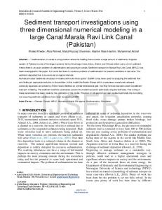
This technique establishes the mathematical framework for information hiding by using a wellknown principle of modulation and the low-pass filter property of human eyes in the context of visual information hiding. This serves as the basis of the optical watermark shown in Fig.1.
IJSER
Algorithms
Information Carrier Structure
Phase modulation
Embedded Image
Binary Image
Fig.1.Embedding by Phase Modulation.
A) Basic Information Carrier Structure The basic (or simplest) information carrier structure can be a dot array, a simple repetitive structure. The dot array can be represented by a reflectance function. B) Phase Modulation to Embed Binary Images into Basic Information Carrier Structure In phase modulation of Fig.1 a binary image is embedded along either x axis or y axis. The binary image is modulated in the direction of x axis, by shifting the image with a half period of dot matrix in the x direction. The basic information carrier structure is generated by using in Eq. (1), [2].
I] Information Hiding by Phase Modulation
IJSER © 2013 http://www.ijser.org
International Journal of Scientific & Engineering Research, Volume 4, Issue 5, May-2013 ISSN 2229-5518
671
The demodulation is achieved by implementing Eq. (6) and (7). (1) (6)
The phase-shifted dot array can be represented by Eq. (2) and (3),
(7)
(2)
Here, d(x,y) is used to demodulate. Fourier series expansions is applied to Eq. (1), (2) and (3) and get results Eq. (8), (9) and (10) respectively.
(8)
(3) Each f 1 (x,y) and f 2 (x,y) are corresponding to a modulation direction.
IJSER
Where δ(x) = 0,
|x| > ½
δ(x) = 1,
|x|