This "shower door" effect hampers the use of this technique in animation .... we achieve a projec- tion of the texture from object to screen space and vice versa.
Eurographics/ IEEE-VGTC Symposium on Visualization (2007) Ken Museth, Torsten Möller, and Anders Ynnerman (Editors)
Hardware-accelerated Stippling of Surfaces derived from Medical Volume Data Alexandra Baer
Christian Tietjen
Ragnar Bade
Bernhard Preim
Department of Simulation and Graphics Otto-von-Guericke University of Magdeburg, Germany {abaer|tietjen|rbade|preim}@isg.cs.uni-magdeburg.de
Abstract We present a fast hardware-accelerated stippling method which does not require any preprocessing for placing points on surfaces. The surfaces are automatically parameterized in order to apply stippling textures without major distortions. The mapping process is guided by a decomposition of the space in cubes. Seamless scaling with a constant density of points is realized by subdividing and summarizing cubes. Our mip-map technique enables arbitrarily scaling with one texture. Different shading tones and scales are facilitated by adhering to the constraints of tonal art maps. With our stippling technique, it is feasible to encode all scaling and brightness levels within one self-similar texture. Our method is applied to surfaces extracted from (segmented) medical volume data. The speed of the stippling process enables stippling for several complex objects simultaneously. We consider application scenarios in intervention planning (neck and liver surgery planning). In these scenarios, object recognition (shape perception) is supported by adding stippling to semi-transparently shaded objects which are displayed as context information. Categories and Subject Descriptors (according to ACM CCS): I.3.7 [Computer Graphics]: Three-Dimensional Graphics and Realism -Color, shading, shadowing, and texture
1. Introduction The effective visualization of complex anatomic surfaces is a challenging task since nested surfaces and complex geometries are involved. With conventional surface and volume rendering, it is often not possible to convey object shapes and depth relations precisely. This gave rise to sparse visual representations, such as hatching and stippling [VKG05]. Saito and Takahashi [ST90] as well as Interrante and Kim [IK01] showed that depth perception of medical surface models can be effectively enhanced by hatching along curvature directions. Hatching requires high-quality smooth surface models which are very difficult to create automatically based on clinical patient data exhibiting noise and minor artifacts, e.g. © The Eurographics Association 2007.
from breathing, pulsation or patient movement. Without a well-defined curvature field, hatching may be misleading by emphasizing erroneous features of the surfaces. Stippling, in principle, requires high-quality surface models. However, since stippling does not produce visually striking primitives such as lines, this technique is better suited for visualizing surface models with moderate or average quality. Compared to hatching, stippling is more adequate for objects which do not exhibit ridges, valleys or other regions of high curvature. Stippling is a rendering technique, where small dots are used to convey shape and shading. The points’ density and their location on the surface affect the appearance of a stippled object. While densely distributed dots achieve the im-
Baer et. al / Hardware-accelerated Stippling of Surfaces derived from Medical Volume Data
pression of dark shading, sparsely covered regions seem like brighter shaded areas. The points are distributed randomly, but the spacing among the points is regular without any linear or regular pattern.
even because the object moves over a sequence of frames. This "shower door" effect hampers the use of this technique in animation sequences, in which particles should move along with the object.
We present an effective hardware-accelerated stippling method. Compared with existing methods, our approach has the following advantages:
In object space approaches, NPR primitives are associated with actual locations on the model’s surface to achieve frame-coherence. Meier [Mei96] used painterly strokes and Cornish et al. [CRL01] developed a view-dependent particle system in which the distribution and density of strokes is regulated by a hierarchical clustering algorithm. Similarly, Pastor and Strothotte [PFS03] proposed a concept to generate interactive stippling animations using graphics hardware. They consider each vertex as a potential location of one stippling point. The amount of stippling points, according to shading tones and scaling, will be achieved by subdivision and simplification of the object geometry. As the amount of points depends on the number of vertices, time consuming preprocessing steps are necessary. The point distribution is realized with a point hierarchy based on the polygonal mesh and a point relaxation.
1. It is frame-coherent and therefore suitable for animations and interactive exploration. All operations for texture coordinate generation, access and mapping are supported by graphics hardware. 2. Our multi-cube mapping algorithm minimizes texture distortions and integrates different shading tones and scales in one texture while satisfying the constraints of Tonal Art Maps [PHWF01]. 3. The performance is independent of the number of stippling points. Moreover, no preprocessing is necessary to realize a stippling rendering for any object. In this paper, we describe our stippling approach and present scenarios, in which stippling is applied for intervention planning purposes. In contrast to medical education, where the author may, in principle, work for a long time to create a few expressive visualizations, intervention planning is a routine task, which has to be accomplished very fast. Therefore, automatic adjustment of parameters and rendering speed are also considered. Stippling should be used for context objects which serve as orientation aids and not for the focus objects, e. g. a tumor, which are immediately relevant for an intervention. Therefore, accuracy is not an important issue. The major source of uncertainty for these visualizations is the segmentation process, not the stippling approach. 2. Related Work Image-, object- and texture-based methods are the main approaches to illustrate objects with stippling or other rendering styles. Deussen et al. [DHvOS00] and Secord [Sec02] produce high-quality stippling images based on greyscale images as input. Both use distribution methods based on Voronoi diagrams and relaxation to achieve a regular positioning of stippling points that avoids nearly all visual patterns. While the presented images are visually attractive, these image-based approaches are restricted to single renditions. The stippling point distribution obtained in one frame is not guaranteed to correspond with the one obtained in the next frame. Secord et al. [SHS02] propose a method where frame-coherence is pursued on the image plane, not in object space. Stippling points or hatching strokes (see Eissele et al. [EWE04]) are attached to the model’s surface. This approach is not frame-coherent in object space and the nonphotorealistic rendering (NPR) primitives (e.g. points for stippling or strokes for hatching) will move across the object’s surface during an animation by shading changes or
Lu et al. [LME∗ 02] introduced an interactive volume visualization that simulates stippling drawings, thus combining traditional volume and NPR illustration techniques. Each volume is illustrated with an appropriate number of stippling points initially generated. Treavett and Chen [TC00] and Sousa et al. [SESS05] apply NPR techniques to scientific and medical datasets to improve comprehensibility of medical education and surgical training examples. Texture-based methods combine aspects of image- and object-based approaches. Textures with stippling points or hatching strokes are mapped to the surface of the input model. The first stippled renditions were presented by Winkenbach and Salesin [WS94] for parametric surfaces using randomness to distribute the points on the texture and therefore on the surface of a model. They also developed prioritized stroke textures to apply a hatching pattern in object space. Klein et al. [KLK∗ 00] used Art Maps and Praun et al. [PHWF01] introduced Tonal Art Maps (TAMs) and lapped textures. TAMs are a sequence of hatch images representing different tones and mip-map levels. Strokes within the images are scaled to have an appropriate stroke size and density at all resolutions. They are organized to maintain coherence across scale and tones. Yuan et al. [YNZC05] introduced a 2D geometry-image processing method to generate stippling renditions. Points are directly rendered and therefore the frame rate is roughly inversely proportional to the amount of generated stippling points.
3. Theoretical Background and Overview Image space methods are normally fast, but since the points are placed in image space, undesirable effects (e. g."shower door" effect) may appear. Object space methods are frame coherent but commonly require time-consuming preprocess© The Eurographics Association 2007.
Baer et. al / Hardware-accelerated Stippling of Surfaces derived from Medical Volume Data
ing steps. Texture-based methods are as fast as imagebased techniques, frame-coherent like object-based approaches and furthermore predominantly geometry independent. However, mapping color information from a 2D image or some other signal from a 2D domain to a 3D surface is challenging. The quality of the result heavily depends on the quality of the underlying surface parametrization. To avoid any texture distortion, Floater and Hormann [FH04] argued that the parameterization should be angle-preserving (conformal) and area-preserving. Isometric mapping is the optimum, but this is only feasible for developable surfaces like cylinders, cones and cubes. The main problem relates to the geometry of polygonal surface models. Since these meshes are defined at the vertices, an analytical parametrization is not possible. We developed a hardware-accelerated technique that visualizes 3D medical surface models using textures to simulate stippling drawings. Our mapping method borrows from cube maps and the PolyCube-Maps of Tarini et al. to avoid distortions on a 3D surface [THCM04]. Cube maps are usually deployed for environment mapping, but they can also be used to define a seamless texture mapping. With cube mapping, the 2D texture is first mapped to a cube to transform 2D texture coordinates into 3D texture coordinates. Cubes are suitable as intermediate objects because they can easily be parameterized mathematically. Every 3D texture position on the cube‘s surface is associated with a position in the 2D texture space. In the second stage, a 3D texture position is assigned to each vertex of the 3D object. Polycubes are a variant of cube maps and enable cube mapping for models with arbitrary shapes. The cube used for cube mapping is substituted with a polycube, a shape composed of axis-aligned unit cubes that are attached face to face and roughly resemble the shape of the given mesh. Our approach to texture mapping is similar to the polycube method, but instead of preprocessing an object specific polycube, we automatically subdivide the individual object space into unit cubes. This is possible because of the stippling texture we are using. The texture access and mapping process are simple enough to be implemented in currently available graphics hardware. Moreover, we designed a stippling texture and realized a mapping process that minimizes texture distortions and enables automatic mip-mapping. To satisfy the spatial and temporal coherence for real-time rendering, we used the TAMs method and assigned it to stippling points (recall Praun et al. [PHWF01]). Furthermore, we present a self-similar texture that integrates all stippling images (different shading tones and mip-map levels) used for the TAM.
4. Texture-Based Stippling Algorithm The visualization of an object with texture-based stippling, involves two major tasks: © The Eurographics Association 2007.
• the texture design including the representation of various shading tones by the density of stippling points and • the texture mapping process based on a parametrization that minimizes texture distortion. In this section, we present the texture mapping process followed by the texture design. The mapping technique will be introduced initially to carefully explain the texture design requirements. 4.1. Texture Mapping Process Mapping a texture to a polygonal model of arbitrary shape, e. g. concave or branching objects, requires an appropriate surface parameterization. We introduce a cube mapping approach to map a 2D texture to a 3D object. More precisely, we modify the idea of polycubes that enable a mapping process with low distortion to achieve an object specific texture mapping without object preprocessing. This modification is possible because there are just points on the texture that have to be mapped onto the surface. The following section covers the texture mapping process consisting of the object parametrization, the calculation of texture coordinates, the texture selection and mapping. 4.1.1. Object Parametrization An object parametrization is a transformation that associates all points in texture space with points on the object surface. We introduce a method that is based on the PolyCubeMap technique. Instead of constructing an object-resembling polycube structure, we divide the object space into axisparallel unit cubes and then perform cube mapping for every single cube (see Figure 1 (a)). We refer to this cube structure as multi-cube structure. Thus, we achieve a global parametrization for every object without object-specific preprocessing steps. Constructing the multi-cube for an object initially requires the calculation of the cube’s size. The cube size is based on the texture size consisting of T × T texture elements (texel) where T must be a power of two. To determine the cube’s extent, we take the texture size in screen space Ts and project this size to the bounding box center of the object in object space (inverse mapping). We choose the object’s bounding box center to consider the distance from viewpoint to object in our technique. The texture size in object space To is used as the edge length for each unit cube. This inverse mapping approach for the cubes enables the adjustment of the cube size to the objects’ extent. Besides that, we achieve a projection of the texture from object to screen space and vice versa with low distortions. The object lies within this multi-cube construction and will be thus parametrized for the mapping process (see Figure 1 (a)). The cubes act as a surface for cube mapping and every single cube can be treated similarly. First of all, the
Baer et. al / Hardware-accelerated Stippling of Surfaces derived from Medical Volume Data
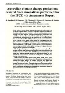
(a)
(b)
(c)
(d)
Figure 1: The pipeline of our texture-based stippling algorithm explained by using a kidney surface. (a) To parameterize the object for texture mapping, the object space is divided into axis-parallel unit cubes (multi-cube). Cube mapping is performed for every cube. To assign a texture position to each surface point, (b) the normalized surface normal (here mapped to a color in RGB-space) and (c) the light intensity at each surface point is calculated. The light’s intensity is used to select a texture with the appropriate number of stippling points (d) to represent the shape with stippling.
stippling texture is projected to each side of a cube and then mapped to the objects surface. To assign a texture position on a cube side to each surface point, we use the normalized surface normal of every surface point (see Figure 1 (b)). As in other cube mapping algorithms, the normals’s major direction – defined as the largest component of the vector – determines the cube side that has to be considered for the texture coordinate calculation. The intersection point of the normal vector with the cube side serves as an index for the texture access to the corresponding texel for each surface point. The mapping process is performed per fragment with fragment shader programs to achieve a hardware-accelerated continuous texture mapping and will be explained in the following section. There are two major sources of distortions that will be considered and minimized with our parametrization. First, the texture distortion at the object’s surface by subdividing the object into cubes and second the distortion that may appear by projecting the texture to screen space.
surface normal and the corresponding cube side are the only requirements for our approach. For this reason, all computations to obtain the texture coordinates are performed on the basis of one cube that acts as a reference cube. The reference cube is defined as an axis-parallel cube with min = (0, 0, 0) and max = (Cubesize,Cubesize,Cubesize) and Cubesize being determined according to the texture size (recall Section 4.1.1). The stippling texture is mapped to each cube side and the texture position (rc , sc ,tc ) is defined as the intersection point of the normal vector starting from the points’ position p = (x, y, z) and the cube side. Since we are performing all operations on the basis of the reference cube, the surface points’ position is initially transferred into the reference cube. We simply use the modulo function to get the new position pc = mod(p,Cubesize) with pc = (xc , yc , zc ). This pc will only be used for the calculation of the texture coordinate
4.1.2. Generation of Texture-Coordinates Figure 1 illustrates the pipeline of our technique that is supported by graphics hardware. All necessary operations to generate texture coordinates as well as the texture selection and access are implemented in a single rendering pass. Having built the multi-cube construction, the texture coordinates have to be assigned to each surface point. This is performed per fragment with a shader program. Section 4.1.4 introduces the lighting operations and necessary vertex transformations that are performed with the vertex shader. The shader programs handle every vertex of the object’s surface and the generated fragments similarly. In Figure 2 (a), our method is illustrated. Since all cubes are equal and the surface points lying in this cube are treated similarly, the relative position of the point in the cube, its normalized
(a)
(b)
Figure 2: 2D sketch of the multi-cube method: (a) each cube can be treated equally for the texture position calculation. Only the relative position of each surface point according to a cube is important. (b) The major direction of the surface normal will select the cube side, even if another cube side is hit first (see p2 and ~n2 ). This minimizes texture distortions.
© The Eurographics Association 2007.
Baer et. al / Hardware-accelerated Stippling of Surfaces derived from Medical Volume Data
and not as displayed pixel position. The cube side that has to be considered for the intersection calculation is selected by the major component of the normal vector. We just use the major direction (largest component) of the normal vector to select the side, even if another side is hit first. With this approach, the texture distortion will be minimized. Figure 2 (b) shows an example for two neighboring points p1 and p2 . The normal vector ~n2 first intersects another cube side but the direction of this vector will select the second intersection point to be the correct one. The area on the cube’s side between the two intersection points with ~n1 and ~n2 will be mapped to the object’s surface. If we would choose the first side for ~n2 to be the appropriate side, the texture distortion would exceed. To set up an equation for a straight line that intersects one cube side, the position pc and the related normal vector ~n p are used. The cube side itself can be considered as an axisparallel plane. Afterwards, the intersection point pi will be mapped to the interval [0,Cubesize] to achieve a pi that is definitely within the cube boundaries. This is necessary because we are performing all operations based on one reference cube. The (rc , sc ,tc ) coordinates are now used to access the corresponding texel of the 2D stippling texture. 4.1.3. Texture Access and Mapping The texture access and mapping is carried out per fragment as well as the texture coordinate computation. The intersection point and the reflected intensity at each point act as an index for the texture access. First of all, the intersection point defines the texture position (rc , sc ,tc ) on the cube side and is within [0,Cubesize]. To access a texel, the position is normalized to the interval [0, 1]. Afterwards, we have the correct texel and only require the stippling texture with the corresponding shading tone for this current surface point (see Section 4.3.1). Since all models presented in this paper are derived from clinical data, the shading and therefore the points’ distribution are influenced by surface artifacts, e. g. stairs or plateaus caused by reconstructing surfaces from binary segmentation results. To render a surface, we compute its desired tone value by performing diffuse lighting computations per vertex (vertex shader) and render the surface using the stippling textures of the appropriate tones. Different shading tones of the object’s surface are represented by the amount of stippling points (recall Figure 1 (d)). A stippling texture with the corresponding point density is then determined according to the reflected intensity. The intensity is composed of the specular and diffuse reflection and will be passed to the fragment shader. All textures are gray-encoded in one texture (see Section 4.3.1). Therefore, we compare the gray value of the texel with the reflected intensity. If the texel’s value is higher or equal, the surface point will be black otherwise white. We implemented an extended variant to improve the object recognition for neighboring structures in one scenario, in which white is replaced by an object-specific color and transparency (see Figure 5). © The Eurographics Association 2007.
4.1.4. Shader Program Each vertex and each fragment, that enters the corresponding shader program, will undergo the following instructions independently. The vertex shader program covers the following operations for each vertex including the preprocessing for the fragment shader: 1. compute the homogeneous vertex position (gl_Position), because the shader replaces the fixed function pipeline, 2. perform diffuse lighting computation: reflected intensity composed of the specular and diffuse reflected amount of light and pass this varying variable to the fragment shader, 3. copy incoming vertex position and normal vector into varying variables (p, n) to enable the fragment shader to process them. The fragment shader program covers the following operations that are necessary for texture coordinate generation, texture access and mapping: 1. define cube extension: min = (0, 0, 0) and max = (Cubesize,Cubesize,Cubesize), where Cubesize is passed to the fragment shader as a uniform variable, 2. compute position in reference cube: pc = mod(p,Cubesize) (recall Section 4.1.2) 3. determine the largest component of the surface normal and use this result to calculate the intersection point of n with the selected cube side, 4. the intersection point is mapped to texture interval [0, 1] for texture access, 5. access texture with computed texel value and use it as Look-Up table according to reflected intensity (see Section 4.3.1). 4.2. Multi-Cube Mip-Mapping In order to use texture mapping for interactive stippling, an appropriate mip-mapping concept is necessary. For instance, when objects are magnified the stippling points should maintain the same size and the represented shading tones should be constant over the enlarged screen space area (see Figure 3 (a)-(c)). Because of that, the stippling points can not be scaled like the object. A constant stippling rendering will be achieved, if stippling points appear while magnifying and disappear while minifying the object. To get consistent density and size of stippling points on the screen, we apply distance-dependent cube splitting. The cube size changes according to the object and texture size on the screen. First of all, we compute the cube size as described in Section 4.1.1. We keep the initial size until the object is scaled. To receive a potential new cube size, we determine the texture’s extent in screen space. If the object is magnified and therefore the texture exceeds 1.5 of its current size in screen space, the cube’s edge length will be halved. If the object is
Baer et. al / Hardware-accelerated Stippling of Surfaces derived from Medical Volume Data
(a)
Figure 3: Stippling points appear while magnifying and disappear while minifying the object. Large structure representations contain more stippling points than smaller object representations. The point size remains constant over different scales.
minified and therefore the texture size equals almost halve of the current size, the new cube size is doubled and 8 cubes are summarized to one. However, our approach realizes seamless scaling automatically by subdividing and summarizing cubes. This technique requires self-similar textures to avoid floating points on the surface while mip-mapping. Blending between different cube sizes and the special texture design (introduced in Section 4.3.2) avoids visible transitions. This technique enables scaling without being restricted by the texture and cube size. 4.3. Texture Design With stippling, the density and location of small dots convey shape and shading of objects. While densely distributed dots achieve the impression of dark shading, sparsely covered regions seem like brighter shaded areas. Similar to the TAMs from Praun et al. [PHWF01], we discretize the range of tone values and construct a sequence of stippling textures representing these discrete tones. By producing diverse levels of textures with different numbers of stippling points, we achieve different shading tones. In contrast to Praun et al., we only need one gray-scale image for all shading tones and mip-map levels. 4.3.1. Shading Tones We design the shading tones such that darker tones contain all the stippling points of brighter tones. This point coherence across tones avoids floating of points over the object ("shower door" effect) and guaranties continuity of points so that points only appear when illumination is getting darker and disappear when illumination is more intense. Following this definition of point-continuity over tones, the darkest tone contains the points of all brighter tones and some additional ones. We use this observation to encode all tones in one gray-level texture. Similar to real-time halftoning by Freudenberg et al. [FMS02], we first create a set of tone layers that contain black stippling points. An example is shown
(b)
Figure 4: (a) Texture layers (1 brightest tone - 3 darkest tone) and resulting texture that encodes different tone layers with unique gray values. (b) One texture tile is replaced by a patch of (2 × 2) tiles of the same texture and vice versa. The (2 × 2) patch of a texture contains the scaled version of itself (gray dots).
in Figure 4 (a), where texture 1 represents the brightest tone and texture 3 illustrates the darkest tone. Then each layer is encoded by an increasing gray value starting with the darkest tone to the brightest layer (see Figure 4 (a)). The representation of all tone layers in one is possible because of the point coherence across different tones. 4.3.2. Self-Similar Mip-Map Textures To minimize texture magnification and point size variation, we apply distance-dependent cube splitting and collapsing (recall Section 4.2). Hereby one texture tile is replaced by a patch of 2 × 2 tiles of the same texture and vice versa. Thus, no separate mip-map textures have to be generated. To achieve coherence between stippling points of one texture tile and a 2 × 2 patch of it, it is necessary to ensure that the 2 × 2 patch contains the scaled version of the texture (see Figure 4 (b)). Thus, we developed a self-similar texture to avoid floating of stippling points while mip-mapping. Unfortunately, with this constraint it is more challenging to design a stippling texture with randomly distributed but equally spaced points without any linear or regular pattern. To support the texture design process, we developed a semiautomatic method that overlays the current texture by its 2 × 2 tiles during the texture design process (see Figure 4 (b)). We did not attempt to achieve a fully automated procedure since there is no need for designing a large variety of stippling textures. Indeed, all objects stippled in this paper are achieved with the same texture. 5. Results We implemented the shader programs with the OpenGL Shading language and all results shown in the paper are generated interactively for a viewport of 512 × 512 pixel, on an Intel Pentium4 processor with 3.2GHz and NVIDIA Quadro FX2000 GPU. The important operations are performed on the GPU (recall Section 4.1.4), except the cal© The Eurographics Association 2007.
Baer et. al / Hardware-accelerated Stippling of Surfaces derived from Medical Volume Data
(a)
(b)
(c)
(d)
Figure 5: Medical surface models rendered with our texture-based stippling method. (a) The bones and (b) the head including the muscles, vessels and glands and are exclusively represented by stippling. A combination of stippling with the object specific color and transparency to illustrate the context objects with stippling and emphasize (c) the lymph nodes, tumor of the head and (d) the liver with tumor and vessels for the thorax scenario.
culation of the cube size. In Figure 5, we present some medical surface models generated by our texture-based stippling method. The models are derived from clinical CT data, based on segmentation, surface generation and subsequent smoothing. These models are typical anatomic structures. However, we do not claim these to be representative. The texture used for all models is 16×16 pixel and integrates 8 different tones beginning with white. All performance values related to the models, containing the hip and the liver vessel from the front page, are presented in Table 1. As expected, the more polygons the lower the frames per second (fps). Furthermore if stippling is applied, the fps will decrease because of the texture mapping process, but this is not significant since the mapping process is performed only once. Note, that due to our stippling approach, the fps do not depend on the number of stippling dots. Table 1: Performance of our stippling technique. Models Kidney Head combined Head stippling Hip Bones Vessel Thorax
Polygons 5.298 73.728 78.332 99.089 146.319 167.232 324.568
only Shading (fps) 61.0 24.2 23.7 21.5 16.0 13.5 6.0
with Stippling (fps) 60.1 21.7 21.1 19.3 11.1 9.1 5.6
The stippling dots are small to avoid the impression of surface properties, induced by stippling visualization. Stippling only represents the model’s shape, extension and position, to integrate the model into the scene as context object. While Figure 5 (a) is a stippling representation of one structure, Figure 5 (b) integrates various structures. This example clarifies the arising problems for different neighboring structures © The Eurographics Association 2007.
that are rendered with stippling. In this scenario, it is difficult to identify and distinguish the different anatomic structures. Because of that, we present a combination technique, shown in Figure 5 (c) and (d). Instead of black dots and white background we choose black dots and object-specific colors and transparency. The additional individual structure properties (color, transparency) support the object recognition. In combination with stippling, the structure’s shape and position is emphasized. Even though we are not performing any additional algorithms to distribute the points, there are no disturbing point patterns visible. 6. Conclusion and Future Work We developed a texture-based stippling technique for arbitrary object shapes, such as anatomic structures. Based on the multi-cube structure, we can ensure that the stippling texture is not severely distorted, even in regions of high curvature. The multi-cube (parametrization) automatically adapts to the objects extension and scaling. The texture design facilitates different shading tones and scales by adhering to the constraints of TAMs. Seamless scaling with a constant density of points is realized by subdividing and summarizing the cubes used for object parametrization. Furthermore, our mip-map technique and self-similar texture enables the object to be scaled without being restricted by a texture size or number of mip-map textures. We optimized the performance by consequently employing graphics hardware. Our technique avoids timeconsuming preprocessing and individual object modifications, because the displayed stippling points do not depend on the amount of existing vertices. Moreover, the performance is not dependent on the amount of illustrated stippling points. Due to the high performance, stippling can be enabled simultaneously for several complex anatomic struc-
Baer et. al / Hardware-accelerated Stippling of Surfaces derived from Medical Volume Data
tures. Moreover, our stippling technique provides framecoherence which is essential for interactive exploration and animation. Thus, this approach is applicable for the visualization of context objects in intervention planning. There are a few extensions, left open for future work. First of all, it is desirable to integrate more parameters than the reflected intensity for texture (tone) selection. The reflected amount is one important criterion but especially local areas of high and low reflectance need additional adjustments to improve the point distribution. For example the local surface curvature or intensity are two parameters that may influence the texture selection for one surface point. Furthermore, the combination of different NPR-rendering styles (e. g. like hatching, silhouettes, feature lines) with stippling and the combination with color for specific therapeutic questions of medical surface models has to be analyzed to generate supportive medical illustrations. References [CRL01] C ORNISH D., ROWAN A., L UEBKE D.: Viewdependent particles for interactive non-photorealistic rendering. In Graphics Interface (2001), Canadian Information Processing Society, pp. 151–158. [DHvOS00] D EUSSEN O., H ILLER S., VAN OVERVELD C., S TROTHOTTE T.: Floating points: A method for computing stipple drawings. Computer Graphics Forum 19, 3 (2000), pp. 40–51. [EWE04] E ISSELE M., W EISKOPF D., E RTL T.: Frameto-frame coherent halftoning in image space. In Theory and Practice of Computer Graphics (2004), IEEE, pp. 188–195. [FH04] F LOATER M. S., H ORMANN K.: Surface parameterization: a tutorial and survey. In Advances in Multiresolution for Geometric Modelling (2004), Springer, pp. 157–186. [FMS02] F REUDENBERG B., M ASUCH M., S TROTHOTTE T.: Real-time halftoning: A primitive for non-photorealistic shading. In 13th Eurographics Workshop on Rendering (2002), Springer Wien New York, pp. 227–232. [IK01] I NTERRANTE V. L., K IM S.: Investigating the Effect of Texture Orientation on the Perception of 3D Shape. In Human Vision and Electronic Imaging VI (2001), vol. 4299, SPIE, pp. 330–339.
[Mei96] M EIER B. J.: Painterly rendering for animation. In Proc. of SIGGRAPH 96 (1996), pp. 477–484. [PFS03] PASTOR O. E. M., F REUDENBERG B., S TROTHOTTE T.: Real-time animated stippling. IEEE Computer Graphics and Applications 23, 4 (2003), 62–68. [PHWF01] P RAUN E., H OPPE H., W EBB M., F INKEL STEIN A.: Real-time hatching. In Proc. of SIGGRAPH 01 (2001), pp. 579–584. [Sec02] S ECORD A.: Weighted voronoi stippling. In Second international symposium on Non-photorealistic animation and rendering (2002), ACM Press, pp. 37–43. [SESS05] S OUSA M. C., E BERT D., S TREDNEY D., S VAKHINE N. A.: Illustrative visualization for medical training, visualization and imaging. In Computational Aesthetics (2005), pp. 201–209. [SHS02] S ECORD A., H EIDRICH W., S TREIT L.: Fast primitive distribution for illustration. In 13th Eurographics Workshop on Rendering (2002), Debevec P., Gibson S., (Eds.), Springer-Verlag Wien New York, pp. 215–226. [ST90] S AITO T., TAKAHASHI T.: Comprehensible rendering of 3-d shapes. In Proc. of SIGGRAPH 90 (1990), vol. 24(4), pp. 197–206. [TC00] T REAVETT S. M. F., C HEN M.: Pen-and-ink rendering in volume visualisation. In IEEE Visualization (2000), IEEE Computer Society Press, pp. 203–210. [THCM04] TARINI M., H ORMANN K., C IGNONI P., M ONTANI C.: Polycube-maps. ACM Transactions on Graphics 23, 3 (2004), 853–860. [VKG05] V IOLA I., K ANITSAR A., G RÖLLER M. E.: Importance-driven feature enhancement in volume visualization. IEEE Transactions on Visualization and Computer Graphics 11, 4 (2005), 408–418. [WS94] W INKENBACH G., S ALESIN D. H.: Computergenerated pen-and-ink illustration. In Proc. of SIGGRAPH 94 (1994), pp. 91–100. [YNZC05] Y UAN X., N GUYEN M. X., Z HANG N., C HEN B.: Stippling and Silhouettes Rendering in Geometry-Image Space. In Eurographics Symposium on Rendering (2005), Eurographics, pp. 193–200.
[KLK∗ 00] K LEIN A. W., L I W. W., K AZHDAN M. M., C ORREA W. T., F INKELSTEIN A., F UNKHOUSER T. A.: Non-photorealistic virtual environments. In Proc. of SIGGRAPH 00 (2000), pp. 527–534. [LME∗ 02] L U A., M ORRIS C. J., E BERT D. S., R HEIN GANS P., H ANSEN C.: Non-photorealistic volume rendering using stippling techniques. In IEEE Visualization (2002), IEEE Computer Society, pp. 211–218. © The Eurographics Association 2007.