Hardware-Accelerated Template Matching ´ Ra´ ul Cabido† , Antonio S. Montemayor‡ and Angel S´anchez‡ Universidad Rey Juan Carlos, C/Tulip´ an, S/N, 28933 M´ ostoles, Madrid, Spain ‡ {a.sanz, an.sanchez}@escet.urjc.es †
[email protected]
Abstract. In the last decade, consumer graphics cards have increased their power because of the computer games industry. These cards are now programmable and capable of processing huge amounts of data in a SIMD fashion. In this work, we propose an alternative implementation of a very intuitive and well known 2D template matching, where the most computationally expensive task is accomplished by the graphics hardware processor. This computation approach is not new, but in this work we resume the method step-by-step to better understand the underlying complexity. Experimental results show an extraordinary performance trade-off, even working with obsolete hardware.
1
Introduction
Object recognition problems are described as a labeling problem based on models of known objects [1]. Template matching is a very well known feature detection technique used in low level Image Processing and Computer Vision tasks, such as object recognition and tracking. As an image matching technique it compares portions of images against one another [2]. Many kind of implementations have been proposed, although the most basic one is related to the cross-correlation computation in order to compare the image and a pattern using a distance measure. The template matching calculation involves a pixel by pixel analysis of the template into an image portion, evaluating every location of the target image. In a generalized approach template matching should be invariant under scale and rotation transformations. As a consequence, this technique is computationally very expensive. Computer graphics have been very popular during the last two decades for the rapid expansion of computer generated special effects in films, multimedia and computer games. This fact has allowed the evolution of graphics hardware to unprecedent limits. Commodity graphics hardware has evolved since the mid 90’s giving a considerable amount of programming power to developers in order to customize their rendering effects in real time. Apart from that, a consumer graphics processing unit (GPU) has become inexpensive and can be considered a kind of programmable stream processor. Their programmable capabilities has helped the development of applications far beyond rendering purposes. Many
authors have demonstrated that these consumer GPUs have a great raw performance, some times even superior to the most common and powerful CPUs [3–6]. They have been used as a co-processor for the central processing unit (CPU) remaining the idea that they can be encountered in most off-the-shelf desktop computers. Examples of it can be found in applications that exploits the power of the GPU for linear algebra calculations [9–12], physically-based simulations [6], image and volume processing [4, 13–15], neural network implementations [16, 17] or even acceleration of database operations [18] among others [19]. In this work we demonstrate that an efficient template matching based on cross-correlation calculation can be achieved using a commodity graphics card. It has been implemented exploiting the intrinsic parallelism of the graphics hardware. Additionally, we have proposed three kinds of models to increase the efficiency of the process step by step, showing details of their implementation and encountered difficulties. Apart from that, we propose a not-new but recent framework for image processing development that can give ideas to other researchers for customizing their implementations.
2
Graphics Hardware
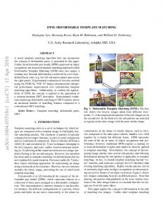
Commodity graphics hardware has evolved drastically since the mid 90’s. With the aid of the rapid expansion of computer games and multimedia technologies these consumer graphics processing units (GPUs) have also become very powerful and inexpensive hardware. Traditionally, these 3D graphics cards implemented a fixed pipeline for the processing of primitive descriptions tuned as a state machine from an API such as OpenGL. But their previously fixed graphics pipeline stages were replaced with programmable components, the transform and lighting (T&L) and the multitexturing one, providing great versatility and power to the developer [7]. The hardware accelerated programmability of GPUs has been exposed to programmers for the development of programs called shaders. These shaders are loaded into the graphics card for replacing the fixed functionality. There are two kinds of shaders, respectively called vertex and fragment shaders. They constitute the executable code of the corresponding programmable components of the graphics pipeline. These shaders are primarily used for rendering complex special effects and realistic images in real-time. The basic CPU/GPU architecture model is outlined in Figure 1. The programmability of the GPU is very well suited for stream computations, in which a simple kernel operation is executed over a large number of elements in a single-instruction multiple-data (SIMD) fashion [8, 9]. Textures and the multi-texturing capability provides some ways of efficient SIMD computation. In this context, a texture is an image that can be mapped to a polygonal structure to provide realism to the model. Basically, as an image, it can represent four values (R, G, B, A) as color and transparency components in every accesible location, called fragments or texels. The programmer is responsible for organizing its data in a grid way to convert them into a texture, so
GPU TEXTURE
FIXED GRAPHICS PIPELINE
CPU
Transform & Lighting
PROGRAMMABLE VERTEX PROCESSOR
Rasterizer
Multitexturing
READBACK
MULTIPASS
RENDERING
TEXTURE
FRAMEBUFFER
PROGRAMMABLE FRAGMENT PROCESSOR
Fig. 1. Basic CPU/GPU programming model. When enabled, programmable vertex and fragment execution paths replace their corresponding stages of the fixed graphics pipeline (represented in dot-lines). Also note the possibility of direct rendering to framebuffer or rendering to another texture (pbuffer), that can be used again as input data in the multipass approach.
creating textures in which texels keep numerical values of interest. As it will be shown in Section 3 and 4, it is desirable to fill the whole capacity of the textures. This is because, in the fragment program, the processing cost of a single channel in comparison to the processing cost of the entire quadruple (RGBA) is similar. In order to operate on the texels, the texture is fixed to a well determined grid. Then, a custom fragment shader is enabled and the operation kernel is executed over every fragment by simply rendering. A schematic visualization of a number of textures applied as input for a fragment program can be seen in Figure 2. The output result can be redirected to the input (by means of a pbuffer) in a multi-pass approach for continuing the processing task (see Figure 1). At this point, it is important to remark that the readback process from video memory to host memory after the rendering step is a computation bottleneck. In this model, a shader is a program executed by the GPU. Originally they had to be coded in assembly, but as the graphics hardware increased in functionality and programmability, these shaders were more difficult to implement. Even more, the rapid evolution of GPUs forced to rewrite previous shaders to get maximum performance when a new family of graphics hardware were released. The solution came with the apparition of comercial high level shading languages and their compilers, which helped in portability and legibility, so improving efficiency in the development process. Nvidia’s Cg, Microsoft’s HLSL and recently OpenGL Shading Language have been the first commercially available languages for commodity graphics hardware with major acceptance. A brief classification, chronology and explanation of these languages can be found in [20].
Output
Tex0 ..... TexN
s
s s t
.....t
t
Fig. 2. Simple fragment program computation. A common fragment program will be executed over every position of the input textures (T ex0-T exN ), for example returning a value at (s,t) in the output texture for values at (s,t) in the input textures.
3
Application to Pattern Recognition: Template Matching
We have developed three models of a basic template matching for being processed on the GPU. Each one of the models increase its complexity but also its efficiency. For demonstration purposes they do not consider rotations and scales. The first model does not exploit the SIMD capability of the graphics pipeline. It only computes the cross-correlation between the template and each location inside the image in a GPU architecture approach. The second model uses the four channels (RGBA) of the template and target textures to compute the cross-correlation in four different positions at a time (at each rendering pass). This model is preferable in respect to the previous one although it is not as efficient as it could be. The third model uses the same philosophy as the second one but computes much more positions. It exploits not only the RGBA data allocation fashion but also the repetition of the template in a texture of equal size than the target image texture. For every model we consider three stages of processing: initialization, distance measurement calculation for a single position and new position estimation or updating. In the initialization stage we can preprocess the input images. In this application, if input images were in color format, an RGB to gray scale conversion is executed as a preliminar rendering with the appropriate fragment program enabled. Another kind of preprocessing could be done in this stage, such as a gaussian filtering to reduce noise artifacts. An intrinsic limitation of the GPU architecture is the lack of global registers in the programmable rendering pipeline. For the template matching, a subwindow is computing a distance function among pixels and, after that, a sum for all distance values is computed in order to get the cross-correlation result. This sum has to be kept for every position to compare the evaluations. As there is no accumulative register, this sum of distance values must be computed in an alternative fashion. A typical way to proceed is by asking for a reduced level of detail (mipmap) of the output texture. That level will offer average values of the corresponding neighborhood of the texture at each fragment. With that
RGBA
Tex0 RGBA
Tex0 Template
Template RGBA RGBA
RGBA
Tex1
Tex1
Subwindow
Subwindows
Tex1 RGBA
RGBA
Average
Output Texture
Average
RGBA Output Texture
RGBA RGBA
a)
b)
Fig. 3. a) Model 1 only takes advantage of the R channel and Tex1 have to be updated at each evaluation to complete the matching. b) Model 2 takes advantage of the RGBA channels. Four subwindows are loaded into an RGBA texture (T ex1). Also, the gray scale template is repeated in each channel of T ex0. Thus, four positions are evaluated in each pass.
average it is easy to obtain the corresponding summation multiplying by the ratio between the number of fragments of the original texture and the number of fragments of the resulted mipmap. This process can be done for power-of-two textures and in cases where precision of one byte is enough for the result. In other cases, a “ping-pong” strategy with two pbuffers is needed.
3.1
Model 1: Red channel exploitation
This is the most limited model but it is easy to understand. It does not exploit the entire quadruple of an RGBA texture, but it can open the mind for next approaches. First, we load the template and an equal size portion of the target image into two textures (T ex0 and T ex1). The RGBA textures have the gray value of each fragment in its RGB channels. It is easy to calculate the difference between the R channels of both textures fragment-by-fragment. By the explained limitation of the GPU, the global value of the matching fitness is done reducing the output texture to one pixel, thus returning in the pixel the average of the whole output texture. This average value is a proportional measure of the summation, and can be kept in system memory to be compared to other results. Figure 3.a outlines the procedure. The performance of this model is very limited because of in each pass we just evaluate one position. Once we have evaluated the matching of the template in that position, we have to “move” the texture coordinates of the target image to load another subwindow and repeat the entire process. Then, the number of rendering passes is proportional to the number of pixels of the target image.
Tex0 R G B A
Template
R G B A
RGBA R
Tex1 G B
A
1 px
Average
Output Texture
Fig. 4. In Model 3 the target image (Lenna) is loaded into the RGBA channels of T ex1, the arrows represent different offsets. The template image is loaded and repeated along the T ex0. In each rendering pass this model evaluates many positions in parallel.
3.2
Model 2: RGBA channel exploitation
This model exploits the RGBA texture channels. Now, the programmer is responsible for organizing its data to produce the textures. The key point is the decomposition of four portions of the target image into the RGBA channels of T ex1 as shown in Figure 3.b. Also, it is important to note that the template is repeated in each channel of T ex0 to make the fragment program work in RGBA. Again, after each rendering pass the texture that contains the subwindows have to be updated (T ex1), allocating portions of the original image in the texture. This process can be computationally expensive, even a main bottleneck depending on the performance of the results readback. 3.3
Model 3: Vectorization and repetition
This model is much more efficient than the previous ones. An outline of this model can be seen in Figure 4. The target image (NxN pixels) is loaded into the RGBA channels of a texture (T ex1). However, there is an offset of 1 pixel in the horizontal direction in each channel except the first one. On the other hand the template (nxn pixels) is loaded into the RGBA channels of T ex0, repeated until having a size equal to the target texture (T ex1). In this way, every texels will have correspondence one each other in the fragment program. The offset of the GBA channels of T ex1 provides a way to evaluate 3 more different positions at the same time, so for each RGBA template subwindow N of T ex0, 4 positions are evaluated. As the template is repeated N n x n times in
Time (s)
Time (s)
40
10000 Model 1 Model 2 Model 3
1000
2048 1024 2048 1024
35 30 25
(32) (32) (16) (16)
20
100
15 10
10
5
a)
x4
x8 CP U
V4 0
CP U
N
V3 4
NV40
N
NV34
N
NV25
V2 5
0
1
b)
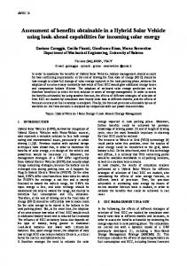
Fig. 5. a) Different models for three different GPUs (target image: 1024x1024; template image: 32x32). b) Comparison between CPU vs GPU (Model 3) performance. Different sizes of square templates and target images are considered.
T ex0, the number of parallel evaluations in each rendering pass is increased to N 4x N n x n . For a 1024x1024 target image and a 32x32 template this leads to 4096 evaluated positions for each rendering pass. The updating rule for this model is quite simple because it only needs the translation of the whole template texture over the target texture. This translation implies no data reallocation after the rendering pass and thus it eliminates a previous explained bottleneck.
4
Experimental Results
Experiments have been performed using 3 different graphics card. The first platform is a Nvidia GeForce4 Ti4600 VGA card (NV25) in a 1.4GHz Pentium 4, 128 MB RAM, AGPx4 (named CPUx4). The second and third platforms use a 3.2GHz Pentium 4, 1GB RAM, AGPx8 (named CPUx8) and respectively a Nvidia GeForce FX5200 (NV34), and a Nvidia 6800GT (NV40). GPU applications have been coded in C using OpenGL as rendering API, Cg 1.2 as shading language and Nvidia v66.93 drivers, while CPU programs were coded in C. Figure 5 shows the experimental results. We have considered the previous 3 models for the GPU implementation and 5 different platforms. In respect to the GPU implementations Model 1 is the worst in terms of efficiency, while, as described before, Model 3 exploits the intrinsic parallelism of the graphics card. Note that Figure 5 a) is semilogarithmic. Figure 5 b) shows that in the latest GPU the performance of this algorithm is very high, even superior to its host CPU performance.
5
Conclusions
We have presented a step-by-step alternative implementation of a well known object recognition method. We have demonstrated that the processor of a modern
graphics card can afford better performance than a modern CPU under certain conditions, in particular, allocating data in a regular and parallel manner. The GPU should operate in a SIMD fashion to get the most performance hit. Experimental results show that the graphics card can be exploited in order to execute non-rendering tasks freeing some computational load to the CPU.
References 1. Jain, R., Kasturi, R., Schunck, B. G.: Machine Vision. McGraw-Hill, Computer Science Series (1995). 2. Baxes, G. A.: Digital Image Processing, Principles and Applications. John Wiley & Sons, Inc (1994). 3. Thompson, C.J., Hahn, S., Oskin, M.: Using Modern Graphics Architectures for General-Purpose Computing: A Framework and Analysis, Int. Symposium on Microarchitecture (MICRO), 2002. 4. Goodnight, N., Wang, R, Woolley, C., Humphreys, G.; Interactive Time-Dependent Tone Mapping Using Programmable Graphics Hardware, Eurographics Symposium on Rendering , (2003) 1–13. 5. Purcell, T.: Ray Tracing on a Stream Processor, Ph. D Thesis, Univ. of Stanford (2004). 6. Harris, M. J.: Real-Time Cloud Simulation and Rendering, Ph. D Thesis, Univ. of North Carolina at Chapel Hill (2003). 7. Olano, M.: A Programmable Pipeline for Graphics Hardware. Ph.D. thesis, University of North Carolina at Chapel Hill (1998). 8. Venkatasubramanian, S.: The Graphics Card as a StreamComputer, Workshop on Management and Processing of Data Streams, San Diego, California, USA (2003). 9. McCool, M., Du Toit, S., Popa, T., Chan, B., Moule, K.: Shader Algebra, ACM Transactions on Graphics (2004). 10. Larsen, E. S., McAllister, D.: Fast Matrix Multiplies using Graphics Hardware, In Proc. Supercomputing 2001. 11. Bolz, J., Farmer, I., Grinspun, E., Schr¨ oder, P.: Sparse matrix solvers of the GPU: Conjugate gradients and multigrid, ACM Trans. on Graphics, (2003) 917–924. 12. Kruger J., Westermann R.: Linear algebra operators for GPU implementation of numerical algorithms. ACM Trans. on Graphics (2003) 908-916. 13. Yang, R., Welch, G.: Fast Image Segmentation and Smoothing Using Commodity Graphics Hardware, Journal of Graphics Tools, (2002) 7(4):91–100. 14. Colantoni, P., Boukala, N., da Rugna, J.: Fast and Accurate Color Image Processing Using 3D Graphics Cards, Proc. of 8th Int. Workshop on Vision, Modeling and Visualization, Germany (2003). 15. Krueger, J., Westermann, R.: Acceleration Techniques for GPU-based Volume Rendering. In Proc. IEEE Visualization 2003. 16. Bohn, C.A.: Kohonen Feature Mapping Through Graphics Hardware. In Proc. of 3rd Int. Conference on Computational Intelligence and Neurosciences 1998. 17. Oh K.-S. and Jung K.: GPU implementation of neural networks, Pattern Recognition, (2004) 37: 1311–1314. 18. Govindaraju, N.K., Lloyd, B., Wang, W., Lin M.C., Manocha, D.: Fast Computation of Database Operations using Graphics Processors, In Proc. SIGMOD 2004, Paris, France (2004). 19. GPGPU Website, http://www.gpgpu.org 20. Rost, R.J.: OpenGL Shading Language. Pearson Education (2004).