Hardware Building Blocks for High Data-Rate Fault-Tolerant In-vehicle Networking F. Baronti&, S. Saponara&, E. Petri&, R. Roncella&, R. Saletti&, L. Fanucci&, P. D’Abramo* & Dept. Information Engineering, University of Pisa, via Caruso 16, 56122 Pisa, Italy * AustriaMicroSystems AG, Tobelbaderstrasse 30, Schloss Premstaetten, A 8141 Unterpremstaetten, Austria {f.baronti, s.saponara, esa.petri, r.roncella, r.saletti, l.fanucci}@iet.unipi.it,
[email protected] Abstract- This paper discusses the hardware implementation of high speed and fault-tolerant communication systems for in-vehicle networking. Emerging safety-critical automotive control systems, such as X-by-wire and active safety, need complex distributed algorithms. Large bunches of data have to be exchanged in real-time and with high dependability between electronic control units, sensors and actuators. According to this perspective, the FlexRay protocol, which features data-rates up to 10 Mb/s, time and event triggered transmissions, as well as scalable fault-tolerance support, was developed and it is now expected to become the future standard for in-vehicle communication. However, collision avoidance and driver assistance applications based on vision/radar systems, poses requirements on the communication systems that can hardly be covered by current and expected automotive standards. A candidate that will play a significant role in the development of safety systems which need data-rates up to hundreds of Mb/s as well as fault-tolerance seems to be the new SpaceWire protocol, whose effectiveness has already been proved in avionic and aerospace. This paper presents the design of the major hardware building blocks of the FlexRay and SpaceWire protocols.
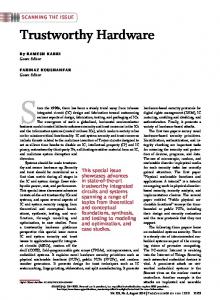
Fig. 1. Bus comparison for in-vehicle networking.
Advanced automotive control systems used for collision avoidance, lane departure warning and parking aid require high-bandwidth sensors (radars and cameras) and communication links with date-rates up to hundreds of Mb/s. Existing high speed automotive networks, such as the MediaOriented System Transport (MOST) or the IDB-1394 (automotive FireWire), are missing specifications in terms of fault-tolerance and reliability. Indeed, they are devoted to transport large amount of data for infotainment instead of safety or driver assistance applications. This challenging issue can be faced introducing the ECSS-E-50-12A standard [8]-[9], known as SpaceWire (SpW), in the automotive field. This protocol provides high level of fault-tolerance as well as high data-rate up to 200 Mb/s (see Fig. 1). Furthermore, it has already demonstrated to be an effective solution in avionic and aerospace systems for cruise control, aerial surveillance and scientific space missions that use high-bandwidth instruments (cameras, radars, x-ray detectors) requiring reliable high-speed on-board communication networks [10],[11]. The key point for the success of both FlexRay and SpW standards lies in the hardware implementation of the relevant building blocks through high performance designs meeting stringent requirements in terms of high-speed, low EMI, high EMC, wide operating temperature range, limited size and costs. This paper, after a brief review of both networking standards, discusses the hardware design of two basic components of the FlexRay and SpW networks: the FlexRay Bus Driver and the SpW Router.
I. INTRODUCTION Automotive control systems are nowadays complex distributed computing systems with various and evolving demands on networking capabilities [1]-[4]. In particular, emerging applications such as X-by-wire or automotive vision subsystems for intelligent driver assistance and safety warnings need in-vehicle networks with stringent requirements in terms of high data-rate, fault-tolerance and deterministic message transmission. According to the Society of Automotive Engineers (SAE), communication protocols can be grouped in 4 classes bounded by the data transmission speed [3]. Class A networks, e.g. Local Interconnect Network (LIN), have a data rate lower than 20 kb/s and are used to transmit simple control data with low-cost technology. Class B networks, e.g. lowspeed Controller Area Network (CAN), can operate up to 125 kb/s and support data exchanges between Electronic Control Units (ECUs), so that the number of sensors can dramatically be reduced by sharing information. Class C networks, such as high-speed CAN, are used for the powertrain and currently for the chassis application domains up to 1 Mb/s. Class D is not formally defined, but it is generally considered that networks over 1 Mb/s belong to class D. As far as X-by– wire applications are concerned, a very promising solution is the upcoming FlexRay standard that operates up to 10 Mb/s [5]-[7] (see Fig. 1).
1-4244-0755-9/07/$20.00 '2007 IEEE
89
II. FLEXRAY NETWORKING FlexRay is a high-bandwidth, fault-tolerant, deterministic communication protocol with many advantages compared to both the very popular CAN protocol and other emerging ones, such as Time-Triggered CAN (TT-CAN) and Time Triggered Protocol version C (TTP/C). These protocols are competing with FlexRay to become the future standard for in-vehicle communications, in particular for x-by-wire applications. Indeed, the FlexRay network accomplishes time-triggered as well as event-triggered transmissions with a bit-rate up to 10 Mb/s making high-speed deterministic communication possible. Thus, the implementation of advanced distributed control systems is dramatically simplified with respect to CAN networking, as the latter provides only asynchronous data exchange at a maximum speed of 1 Mb/s, an order of magnitude lower than FlexRay. Moreover, the TT-CAN protocol, which simply consists of a time-triggered session layer at the top of the CAN protocol stack, does not provide the same level of fault-tolerance as FlexRay and TTP/C, since it does not directly implement important dependability services such as bus guardian, membership service, and reliable acknowledgment [3]. We notice that the TTP/C has similar characteristics in terms of bandwidth and fault-tolerance capabilities, but with higher costs and reduced flexibility compared to FlexRay [4]. TTP/C does not support event-triggered transmission, which is a major drawback in the in-vehicle application scenario where several signals, including user commands and alarms, are inherently asynchronous. Furthermore, FlexRay networking is very flexible and scalable in terms of network topology and fault-tolerance support. In fact, the system can support single-channel configuration, as well as the dual-channel one with some nodes connected to both channels and others connected to only one. Besides, several network topologies are possible, such as linear passive buses, passive or active stars, and hybrid configurations, which can advantageously be utilized to contain a fault propagation. As far as a communication node is concerned, its basic forming blocks are depicted in Fig. 2. The
bus driver implements the physical layer of the protocol and operates as interface between the medium, consisting of two differential lines, and the communication controller. The latter is responsible for message coding and decoding and time synchronization, allowing the application running on the microcontroller to exchange data over the FlexRay network. Fig. 2 also shows that the FlexRay architecture provides a scalable fault-tolerance in terms of dual channel redundancy as well as bus guardian adoption. The bus guardian operates independently from the communication controller and if a failure occurs in the latter (e.g. an attempt to transmit data in a time slot reserved to another node) it denies the bus access disabling the bus driver. In this way, the communication channel can be protected against the existence of faulty nodes on the bus [5]. The FlexRay protocol specification is mature enough to enable the implementation of its basic hardware components on silicon [5],[6]. In fact, there are implementation examples for both the communication controller and the bus driver [12][14]. In particular, the design of the communication controller is fully digital and straightforward since it can rely on the popular E-Ray Intellectual Property (IP) from Bosch [12]. On the contrary, the design of the bus driver is quite challenging, as the reliability of the entire node mainly depends on that of this component. Indeed, its robustness and EMC performance, in terms of very low EM emissions and susceptibility to disturbances are key points for the bus driver design. III. FLEXRAY BUS DRIVER IMPLEMENTATION The first point to be considered when designing a FlexRay bus driver is the fabrication technology that meets the tough requirements of the automotive environment and in particular the upcoming 42 V battery systems. The technology adopted should provide high-voltage and low on-resistance transistors required for the implementation of the transmitter part of the transceiver, as well as a rather high logic gate density needed for the implementation of the non-negligible control section. The example reported in [14] utilizes a 0.35 µm 2P4M CMOS process that provides HV MOS devices, capable of operating from 20 V to at least 120 V with very low on-resistances, similar to those obtainable with BCD processes, and a gate
Fig. 2. General architecture of a FlexRay communication node. Dashed lines highlight optional blocks, which may or may not be included in the node depending on the degree of fault-tolerance needed.
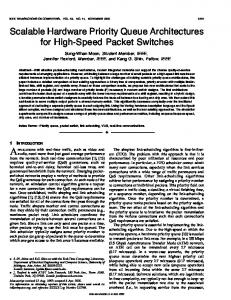
Fig. 3. Functional block diagram of the FlexRay transceiver.
90
density of 17 kgates/mm2 [15]. Another important aspect is the availability of accurate SPICE models for the high-voltage transistors, which may result very useful for fine-tuning the transistor geometrical parameters. The second step in designing the transceiver consists in the identification of the main functional blocks in which the circuit can be partitioned. The accomplishment of this task might lead to the architecture depicted in Fig. 3, which highlights the three digital interfaces toward host, communication controller and bus guardian, together with the transmitter and receiver blocks that provide the link to the two physical lines, named Bus Plus (BP) and Bus Minus (BM) (see Fig. 2). In particular, the application hosted by the microcontroller selects the transceiver operating mode (normal operation mode, receive only mode, and three low-power operation modes: standby mode, power-on standby mode and sleep mode) and reads diagnostic information through the host controller interface. In addition, the wake-up detector block allows the transceiver to leave the sleep state after a wake-up event, which consists of the reception of a wake-up signal from either the bus (remote wake-up) or the wake-up pin (local wake-up). Before going into more detail, it is important to observe that a very tight symmetry of the propagation delays of the data rising and falling edges over the network must be satisfied to guarantee the compliance with the FlexRay protocol specification [5],[6]. That is, the high-to-low and low-to-high propagation delays introduced by both the transmitter and receiver blocks have to be matched with an accuracy of few nanoseconds. Moreover, as the EM emissions are mainly caused by transients of the common mode voltage of the bus lines, particular care has to be adopted in the design of the transmitter circuit in order to achieve a highly symmetrical driving of the two bus lines, so that the common mode voltage on the bus can remain constant also when the bus changes state. As a consequence, the symmetric behavior of the transmitter and receiver is the most critical and challenging issue in the design of the transceiver. From the transmitter design point of view, a good starting point consists in providing a pull-up driver (PMOS transistor) and a pull-down driver (NMOS transistor) for both the bus
min
max
Battery
-0.3 V
+58 V
Bus DC Voltage
-58 V
+58 V
Junction Temp. (TJ)
-40ºC
+150ºC
ESD (HBM)
-4 kV
+4 kV
Latchup immunity
lines. Indeed, this structure is very suitable to achieve the static and dynamic symmetry of the voltage swings on the BP and BM lines, with respect to half of the supply voltage level. However, the strength of all the four transistors must be matched. On the one hand, a “trial and error” simulation procedure to optimize the geometrical parameters of the NMOS and PMOS transistors can be adopted provided that accurate models of the p-channel and n-channel power MOS transistors are available. On the other hand, the employment of the centroid layout technique for both the pull-up and the pull-down transistor pairs can significantly improve the transistor strength matching, by reducing the negative effects caused by gradients in the wafer properties [16]. As far as the receiver is concerned, the comparison of the voltages on the BP and BM lines (the differential voltage between these lines encodes the bus state: idle, Data_0, and Data_1) should be realized with little susceptibility to their common mode voltage, which represents the major way by which disturbances reach the bus driver. This goal can be achieved by attenuating the BP and BM voltages by a resistor divider, so that the common mode voltage of the bus lines can always be maintained into the common mode input dynamic range of the comparators utilized. However, it should be noticed that the two branches of the voltage divider have to be matched from both a static and a dynamic point of view. That is, a careful layout design of the resistors is necessary to equalize the parasitic capacitances as well. The matching of the two branches of the voltage divider represents only a preliminary condition to achieve the symmetry of the propagation delays on the receiver side. This requirement can be met by implementing the comparison function by means of two identical differential comparators driven by the differential bus voltage and the inverted differential bus voltage respectively. The outputs of the comparators are the SET and RESET inputs of a SR-FF, which eventually generates the received data RxD. In this way, we first obtain that the decision thresholds for Data_0 and Data_1 are symmetrical and then that the propagation delays are matched. RxD is a digital signal, so that all the conventional techniques can be employed to avoid pulse-shrinking phenomena from the output of the SR-FF to the corresponding pin. In particular, a high-speed pad can be used to reduce the negative effects of possible different propagation delays of the output circuitry. We finally observe that a successful implementation of a fully compliant FlexRay bus driver [14] has been made possible by following the above described design methodology. Besides, the large set of experimental data measured on more than 500 fabricated devices demonstrates the effectiveness of our design approach to achieve excellent EMC performance and to meet the very demanding operating requirements of the automotive environment. The experimental set-up consisted in two bus drivers connected to form a basic point-to-point FlexRay network and both static and dynamic tests were performed. The purpose of one of the tests was to
-100 mA 100 mA
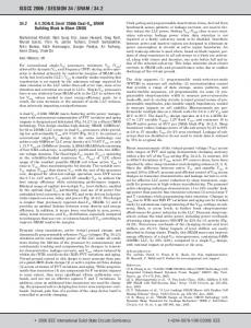
Fig. 4. Microphotograph and maximum ratings of the FlexRay bus driver [14].
91
measure the static differential voltage on the bus when transmitting a 0 and a 1. The statistics of the measurements carried out on about 500 devices were then calculated, in order to evaluate the matching between the transmitter transistors. Other tests consisted in transmitting a sequence of Data_0 and Data_1 to characterize the timing response of both transmitter and receiver circuits. The microphotograph of the die is reported in Fig. 4, which shows that most of the area is due to the transmitter transistors.
diagnostic, reliability and fault tolerance. A basic SpW network is event-driven but, thanks to the exchange of special characters called time-codes, also time-triggered or mixed event/time-triggered communications can be supported. In that case, a node in the network acts as time-master and the others as time-slaves. Several space missions in Europe, US, Japan and Korea have planned the use of SpW which has also been adopted in avionic applications [10],[11]. The availability of reusable and low-complexity IP macrocells, as building blocks (routers and interfaces) of a SpW communication system, is fundamental for the development and spreading of the protocol also in the automotive environment. The state of the art [10],[11] consists of implementations of SpW interfaces or routers compliant only with the basic standard. No SpW router IP core supporting the latest transport layer extensions, PID and RMAP, is presently available. The rest of the paper describes the design of a complete SpW routing and interfacing solution, compliant with RMAP and PID, achieved through novel hardware macrocells targeting FPGA (Field Programmable Gate Array) devices. Different technologies, SRAM-based and antifuse (radiationtolerant and non), were considered and FPGA devices were preferred over the ASIC approach for the following reasons. Firstly, current FPGAs provide enough logic and memory resources and performance (timing, power, operating point) to meet the challenging requirements of aerospace and automotive systems. Secondly, the FPGA non-recurrent cost and development/time-to-market time, much lower than the ASIC ones, are more suitable for a scenario where the standards are not frozen yet. Finally, a large market is not foreseen for space and avionic fields and advanced automotive control systems for active safety, which are still in an evolving phase, can take advantage from the reconfigurability feature of SRAM-based FPGAs .
IV. SPACEWIRE NETWORKING The SpaceWire (SpW) standard proposed by the European Space Agency (ESA) [8] features bi-directional, full-duplex, serial data links up to 200 Mb/s over distances of about 10 m. It is based on Low Voltage Differential Signaling (LVDS) physical layer, resulting in a low-power high-speed link with high immunity to the ground potential difference between diver and receiver and an excellent EMC performance. Data transfers among the different equipments belonging to a SpW network are managed by routers. This topology simplifies connectivity vs. point-to-point direct connections thus reducing the mass and volume of the wire harness. The basic SpW version covers six communication protocol layers: physical, defining the cables and connectors; signal, covering signal voltage levels, noise margins and signal encoding; character, defining the character format; exchange, defining the protocol for initialization of connection, credit–based flow control, error detection and link error recovery; packet, establishing how data are encapsulated in packets for the transfer from source to destination; network, describing the structure of a SpW network, the routing techniques and the addressing schemes (physical, logical or regional). A SpW network can be partitioned in sub-networks called regions: intra-regional communications are based on physical or logical addressing while inter-regional communications are based on regional addressing. Two extensions of the standard, the Protocol Identifier (PID) and the Remote Memory Access Protocol (RMAP) [9], are currently under development by stacking the transport layer on top of the six basic levels. The PID scheme enables many different transport protocols to operate concurrently over a SpW network without interference. A PID = 1 has been assigned to the RMAP protocol, which specifies procedures and command/answer message formats (verified/not-verified, acknowledged/not-acknowledged, CRC type, error types and relevant answers) that allow a SpW network to be configured, SpW nodes to be remotely controlled and data and status information from those units to be gathered. The access procedures from a requesting node to a destination one can be a read, a write or a read-modify-write. For each procedure two different CRC checks are performed on the command field and on the data field of the RMAP message respectively. An authorization key characterizes each node to further increase system security. Furthermore, error detection and error recovery protocols are defined at the transport layer (beside those at exchange layer) to ensure auto
V. SPW ROUTER AND INTERFACE IMPLEMENTATION A. SpW Router and Interface Macrocells The SpW router in Fig. 5 is a VHDL macrocell providing a complete SpW routing and interfacing solution compliant with the basic standard plus the RMAP and PID extensions. The SpW router is a switching matrix connected to the external
Fig. 5. Architecture of the SpaceWire router macrocell.
92
world via a parametrizable number of SpW interfaces (SpW itf), a time-code interface, a control/status interface and a host data transfer interface. The control/status interface provides the host unit with read (for status check) and write (for configuration) access to internal registers of the SpW router and interfaces. The timecode interface distributes system time over a SpW network. Our SpW router can be configured to be the time-master of the network (in such a case the time-code can be generated internally or acquired by an external host CPU) or a time-slave. The switching matrix and the ctrl units in Fig. 5 connect each input port to any other output port. Data transfer through the switch is accomplished after an arbitration phase which grants multiple requests at the same port according to a round robin priority scheme. The routing table provides the address of the destination, i.e. the physical number of the output port bound to the accessed logical address, and group information for group adaptive routing (a feature that allows routing packets to a requested destination over different paths through the network, thus increasing path redundancy and tolerance to link failure). The SpW router is configured by the internal programming interface accessible by a local host through the AHB bus [17] or by a remote node via the SpW bus. The RMAP decoder of Fig. 5 allows the hardware management of the RMAP protocol, defined for configuring a SpW network, controlling its nodes and collecting data from them by writing/reading memories, registers and FIFOs of a node. Our RMAP hardware decoder allows a remote control of the AHB bus from the SpW side. All the accessible registers, FIFOs and memories are mapped to a memory space, where an address is reserved to program the router by means of RMAP commands. When a non-RMAP packet (i.e. a packet with a PID ≠ 1) is received by the RMAP hardware decoder, it is passed on to the host system. This allows other high level protocols to be handled software-wise by the host unit. From an architectural point of view the RMAP decoder & SpW/AHB wrapper unit consists of a finite state machine, implementing the RMAP protocol rules, local memory resources, a dedicated unit for CRC calculation and an AHB wrapper. AHB wrapper in Fig. 5 is a bridge between the SpW router and the AHB AMBA bus [17], a de-facto standard in embedded systems. This module acts as both master and slave on the AMBA bus; it can control the bus to execute a DMA transfer into memory devices, or to initiate a SpW remote control session to a host system connected at AHB. A CAN module can be connected as a slave on the AHB Router interface to link the SpW Router to pre-existing automotive networks. In this case, the Router also acts as a gateway between the CAN and the SpW networks. To this aim, one of the IP macrocells, available in the market, implementing a CAN node with AMBA interface could be reused. The architecture of a SpW interface is sketched in Fig. 6. It is composed of a SpW Codec and a SpW I/O wrapper. The SpW Codec consists of an encoder (or transmitter), a decoder (or receiver) and a finite state machine that implements the
exchange level protocol. The SpW I/O wrapper connects the SpW Codec to the router core through transmitting (TX) and receiving (RX) FIFOs. To avoid the RX FIFO overflow and the consequent loss of data, a credit-based flow control is used. The SpW interface is also responsible for error detection and recovery at the exchange level. The link detects: Parity error, Char Sequence error, Escape Sequence error, Disconnect error and Credit error. If an embedded system needs SpW connections without routing capability, one or more SpW interfaces can be integrated and used in standalone mode through a direct connection to AMBA bus by a wrapper.
Fig. 6. Architecture of the SpW interface.
B.
Validation Flow and Implementation Results The proposed macrocells have been used to build a complete SpW network within ESA space projects [18]. The SpW IP cells have been tested at two levels: (1) test of the VHDL code at functional, post-synthesis and post-fitting levels using an ESA SpW IP Codec as reference link; (2) test of the FPGA prototyped router using as reference a commercial PCI-SpW card in Xilinx FPGA featuring 3 non-routed SpW links plus a SpW link analyzer (see Fig. 7). The SpW router IP has been synthesized on several FPGA devices, i.e. SRAM Altera Stratix II EP2S60 and anti-fuse Actel Axcelerator AX2000. Performed simulations and emulation tests include for example transmission and reception of SpW packets between the SpW links using different types of addressing (Path, Logical and Regional) and communication speeds, programming phase of the router via RMAP or AHB, remote RMAP access to a host on the AHB bus, error detection and error recovery protocols. Anti-fuse FPGAs outperform SRAM-based FPGAs for their tolerance to Total Ionizing Dose (TID) and Single Events Effects (SEE): the RTAX devices, space-qualified versions of the AX devices, bear a TID up to 300 krad with SEU immunity up to 60 MeV cm2/mg; triple-module redundancy and EDAC capability are already implemented at device level. Anti-fuse ensures higher temperature working range and thermal reliability (150oC vs. 100-125oC of SRAM-based FPGA) and a lower power dissipation [19]. However SRAM-FPGAs are reprogrammable and offer reduced development cost. Hence, anti-fuse is the first choice for avionic, military and space applications while the choice for automotive depends on the trade-off between cost and level of reliability to be achieved. The SpW router with 8 links plus AMBA AHB interface has a complexity of about 180 kgates for the logic and 2.8 kB of
93
PC hosting SpW Router board Link Analyser
USB cable
PC hosting the SpW ESA board
X-by-wire and active safety. We first discussed the design of a FlexRay bus driver that represents one of the first fully functional transceivers ever presented. The circuit is able to operate in the harsh automotive environment (suitable for the upcoming 42 V battery systems) and has excellent performance in terms of symmetrical behavior of the transmitter and receiver blocks and of reduced EM emissions. We then presented the design of SpaceWire router and interface hardware macrocells, the first solutions compliant with the newest standard extensions, PID and RMAP. The macrocells have been integrated and tested on both SRAM and antifuse FPGAs. The SpaceWire macrocells represent a promising opportunity for very high speed and fault-tolerant automotive communication systems, which are not currently covered by any standard. ACKNOWLEDGMENT
SpW Router Test GUI
SpW cables
Fig. 7. Emulation test environment.
RAM. It fits on AX2000 FPGA, a device providing 2 Mgates equivalent to roughly 250 k ASIC gates. For the customized 8link SpW router, data-rates higher than 130 Mb/s are supported in worst case conditions on the AX2000, speed grade-3. The occupation is about 80% of the available logic. For the EP2S60 SRAM FPGA, providing roughly 725 k equivalent ASIC gates for the logic, the occupation of the 8-link SpW router is about 25% of the available resources, whereas the transmission rate is up to 200 Mb/s. These data meet the requirements of space, avionic and emerging automotive systems. The router circuit complexity depends on the number of supported SpW links: e.g. a 4-link router can also be fitted on a smaller AX1000 FPGA, providing roughly 125 k ASIC gates, or on EP2S10. As compared to the state of the art, which consists of either radiation-tolerant implementation of only SpW interfaces or SpW routers not including the PID and RMAP extensions, the proposed SpW routing solution is the first IP macrocell, mapped in both anti-fuse and SRAM technology, which is compliant with the complete standard: 6 basic protocol levels plus PID and RMAP extensions. The future implementation of an ASIC router in ATMEL CMOS technology, with a 300 krad TID tolerance and 8 SpW links has been announced in [10] but it is not available yet. The target for this ASIC solution is 200 Mb/s coupled to a power consumption budget of 4 W. The anti-fuse FPGA router power consumption for typical applications is about 1.5 W using a 1.5 V supply for the core and 2.5 V supply for the LVDS I/O, with a saving factor 2.5 as compared to the ASIC router. Another advantage of our SpW interface and router IPs is the higher flexibility. Thanks to parametric HDL design and AHB interface, our IPs can easily be integrated and customized in any embedded system where the designer can define its desired target technology and performance/complexity trade-off. On the contrary, as the requirements in terms of power consumption, number of SpW links and host interface strongly depend on the application domains, the use of the ASIC router will be limited only to the system for which it has been designed.
The SpW work has partially been supported by ESA in the framework of the IPPM project [18] with Aurelia Microelettronica spa, Viareggio, Italy as prime contractor. REFERENCES [1] [2] [3] [4] [5] [6] [7] [8] [9] [10] [11] [12]
[13] [14]
VI. CONCLUSION This paper has presented the design of a FlexRay transceiver and a SpaceWire router, the basic hardware components of the two protocols that are candidates for the future automotive communication standards. They can enable the implementation of high speed and fault-tolerant networking in vehicles, which is mandatory for advanced automotive control systems, such as
[15] [16] [17] [18] [19]
94
H. Kopetz, “Automotive electronics,” Euromicro Conf. on Real Time Systems, (EMRTS), pp. 132-140, 1999. G. Leen, D. Heffernan, “Expanding automotive electronic systems,” IEEE Computer, pp. 88-93, 2002. N. Navet et al., “Trends in automotive communication systems,” Proc. of the IEEE, vol. 93, n. 6, pp. 1204-1223, 2005. T. Nolte et al., “Automotive communications: past, current and future”, IEEE Conf. on Emerging Technologies and Factory Automation (ETFA), vol. 1, 2005, pp. 985 – 992, 2005. FlexRay Communications System Protocol Specification Version 2.1 Revision A, May 2005. FlexRay Communications System Electrical Physical Layer Specification Version 2.1 Revision A, Dec. 2005. R. Makowitz, C. Temple, “FlexRay - A communication network for automotive control systems,” IEEE Int’l Workshop on Factory Communication Systems, pp. 207-212, 2006. “Space engineering, SpaceWire - Links, nodes, routers and networks,” ECSS-E-50-12A, 24 Jan. 2003. “Protocol identification (normative), Ch. 5,” ECSS-E-50-12 Part 2 Draft B, January 2005 and “Remote memory access protocol (normative), Ch. 6,” ECSS-E-50-11 Draft E, 21 Dec. 2005.. S. Parkes et al., “SpaceWire: a spacecraft onboard network for real-time communications”, IEEE-NPSS Real time conf., 2005, pp. 6-10. D. Gwaltney et al., “Comparison of communication architectures for modular avionic systems”, NASA/TM 214431, 2006. A. Techmer, P. Leteinturier, “Implementing FlexRay on Silicon,” Int’l Conf. on Networking, Int’l. Conf. on Systems and Int’l Conf. on Mobile Communications and Learning Technologies (ICNICONSMCL), pp. 3440, 2006. TJA1080 FlexRay transceiver (Preliminary Specification), available at www.nxp.com, Jul. 2006. F. Baronti et al., “FlexRay Transceiver in a 0.35 µm CMOS HighVoltage Technology,” Design, Automation and Test in Europe (DATE), vol. 2, pp. 201-205, 2006. M. Knaipp et al., “Cost effective integration of 70V LDMOS devices in a 0.35 µm standard low voltage CMOS process”, Int’l Seminar on Power Semiconductors (ISPS), pp. 251-254, 2004. Di Long, X. Hong, S. Dong “Optimal two-dimension common centroid layout generation for MOS transistors unit-circuit,” IEEE Int’l Symp. on Circuits and Systems (ISCAS), vol. 3, pp. 2999-3002, 2005. AMBA™ Specification, Rel. 2.0, ARM Limited UK, 13 May 1999. http://www.caen.it/micro/rd_IPPM.php. M. Mason et al., ”FPGA reliability in space-flight and automotive applications”, FPGA and Programmable Logic Journal, 2005.