In general, tailoring a processor architecture for a specific application or set of applica- ... paradigm [2] âhence the name transport triggered architecture (TTA)â ...
Hardware Cost Estimation for Application-Specific Processor Design Teemu Pitk¨anen, Tommi Rantanen, Andrea Cilio, and Jarmo Takala Tampere University of Technology, P.O. Box 553, FIN-33101 Tampere, Finland {teemu.pitkanen, tommi.rantanen, andrea.cilio, jarmo.takala}@tut.fi
Abstract. In this paper, a methodology for estimating area, energy consumption and execution time of an application executed on a specified processor is proposed. In addition, a design exploration process to find suitable processor architectures for a specific application is proposed. Cost and performance estimation is an important part of the exploration process. The actual cost estimation is based on predefined characterizations of cost and performance of resources stored in a database. The results show that the method is quick and its accuracy is sufficient for design space exploration.
1 Introduction In general, tailoring a processor architecture for a specific application or set of applications under certain implementation constraints calls for analyzing several architectural alternatives. This analysis requires several tasks to be performed: program code for the application has to be generated for each target architecture, performance of the code on each architecture has to be evaluated, and implementation costs have to be analyzed. A huge effort is required to perform all these tasks manually. This problem can be alleviated with tool-assisted exploration of a vast architecture design space and a high-level language compiler that is retargetable at run time. In addition, the estimates of the cost of running an application on its target architecture, e.g., execution time, area, and energy, should be obtained. If hundreds of different architecture alternatives are to be analyzed, it is essential that the estimations can be obtained quickly. In this paper, a methodology for estimating area, energy consumption, and execution time of an application executed on a processor is proposed. In addition, a design exploration process to find suitable processor architectures for a specific task is proposed. The actual cost estimation is based on predefined resource characteristics, which are stored into a database used by the exploration process. The estimates obtained with the proposed methodology are compared to reference values obtained from commercial simulation tools. The results show that the accuracy of our method is sufficient for the exploration process and the estimation is extremely quick compared to traditional methods.
FU
FU
FU
RF
RF
LSU
CNTRL
DMEM
IMEM
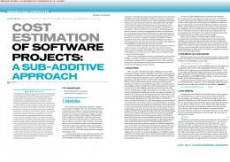
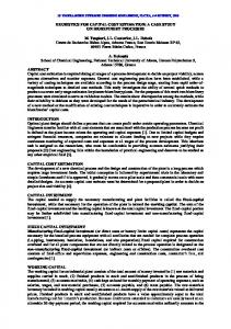
Fig. 1. TTA processor organization. FU: Function unit. RF: Register file. LSU: Load-store unit. CNTRL: Control unit. DMEM: Data memory. IMEM: Instruction memory. Dots represent connections between buses and ports of function units.
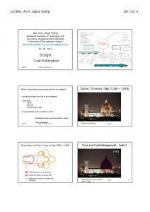
2 Related Work The work presented in this paper is based on the Move framework, a design environment developed at Delft University of Technology, Delft, the Netherlands. The framework consists of a set of tools for designing application-specific programmable processors [1]; it includes a retargetable high-level language (HLL) compiler, a cycle-accurate simulator and a processor generator. The framework provides also tool-assisted architecture exploration; the designer defines the maximum set of processor resources and the explorer estimates the cost of executing the application on different architectures. The processor architectures supported by the framework are all based on the same template. A target architecture is an instantiation of this template with a set of parameters. The tools of the framework can exploit the specific features of each instantiation. The architecture template of the Move framework is based on transport triggering paradigm [2] —hence the name transport triggered architecture (TTA)— where an instruction specifies only the data transports to be performed by the interconnection network. The execution of an operation is a side effect of an operand transport to a specific operand register of a function unit. TTA’s, therefore, remind the data-flow computation paradigm, but the availability of operands is determined statically. In a TTA processor, only one type of operation is supported: the move operation, which performs a data transport from a source to destination. A TTA processor, as illustrated in Fig. 1, consists of a set of function units (FU) and register files (RF) containing general-purpose registers, a control unit, and an interconnection network consisting of buses. Data memory accesses are performed with the aid of a load-store unit, which is a normal function unit from the architecture point of view. The function units and register files can have different number of input and output ports, which are connected to one or more buses. Each function unit begins to execute a new operation when an operand is moved into a trigger operand register, shown in the block diagram in Fig. 2. All the other operands have to be transferred into the operand registers in the same or earlier cycles. A function unit can produce one or more results. If the function unit supports several operations, the actual operation is selected by means of an opcode attached to the move that writes the trigger register. The function units can be pipelined and the latency of a unit is managed by the compiler, which expects deterministic latencies. Dynamic latency has to be managed at run-time by transport pipeline lock mechanism.
tdata
odata1
odata2
oload2 oload1 tload
EN
glock reqlock opcode
trigger register
EN
operand register
operand register
logic EN
pipeline register (optional)
reset clock
EN
logic EN output register (optional) rdata
Fig. 2. Structure of a three-inputs, one-output function unit in a TTA processors.
The design space exploration process used in Move framework, as described in [1], is an iterative process where, in each iteration, the target processor architecture is varied and the performance of the given application running on the processor is evaluated. The user defines the maximum set of resources, i.e., the number of buses, the number and type of FUs, etc. At each iteration of the exploration process, a target architecture, defined by a subset of the maximum resource set, is selected. The given application is mapped and scheduled onto the target architecture and simulated to obtain performance statistics. Finally, estimates of area and speed of the architecture on target technology are computed. In the next iteration, one resource is removed and the map-schedule-simulate-estimate process repeated. Based on the obtained statistics, the next target architecture is selected by removing another resource. This process is repeated until a critical resource is removed, i.e., the application cannot be scheduled without the resource. The critical resource is put back and another one is removed. After a while, the target architecture contains only critical resources and nothing can be removed. At this point, the explorer begins to put resources back, but in different order. The explorer performs a predefined number of such remove-add resource sweeps. After the exploration is completed, the user can pick the target architectures with favorable cost and performance characteristics for further optimizations. The design space exploration process requires estimation of various cost metrics. Different cost metrics of a digital circuit, e.g., area and power consumption, can be estimated at different levels of abstraction. In general, the estimation is a trade-off between accuracy and speed, i.e., better accuracy requires more details of the implementation. There are several tools to obtain accurate estimates of area, delay, and power consumption using physical models. These tools require that the VLSI implementation is available implying that the time consuming place and route phases have been completed. There are also low-level power analysis methods operating at RT-level, which provide
comparable accuracy, e.g., [3] [4]. However, the low-level tools are not especially useful in architectural exploration due to their long simulation times. In [5], several methods of physical modeling, such as Rent’s rule and Donath’s wiring model, have been applied for evaluating the area and delay of the protocol processor architectures. The Rent’s exponents were allocated for each hardware resource in the processor and final cost is obtained with linear approximation. The area accuracy is within 40% of true area. Most of the efforts in power estimation have targeted at compiler optimizations, i.e., creating power-aware software. For this purpose, cycle-by-cycle power estimation is required. The estimation is often targeted to a specific microarchitecture, as with the methods reported in [6] [7]. If architectural alternatives are to be explored, the estimation method has to support higher level models. E.g., in [8], cycle-level performance simulator is used to obtain the hardware access counts. These counts are used to obtain power estimate with the aid of parameterizable power models of the resources. These models are based on effective capacitance and fall into four categories: array structures, fully associative content-addressable memories, combinational logic and wires, and clocking. Since the power models are based on capacitance, the models cannot be obtained automatically from a RT-level design. This implies manual work when new models are created. In [9], the power estimation of a processor core is based on switching capacitance tables. Each function unit is analyzed with all the possible operand combinations. The power accuracy was verified within 10% of results obtained with circuit level simulators while the execution time was less than 0.1 sec per transition. The tabular power figures implies large tables when the number of bits in the inputs is increased. The estimation models can also be obtained automatically from RT-level components as described in [10]. The elementary components are synthesized onto target technology and characteristics are stored into a component-library. The characteristics include both the delay and power consumption. The RT-level components are fairly fine-grained, e.g., full-adders and logic gates, thus complex systems will contain a large number of components. A power estimation method based on a higher level model is proposed in [11], where each functionality of a peripheral device is modeled as an instruction. Each instruction has a corresponding power mode, which allows a powerper-instruction look up table to be created. The power consumption of the processor is still based on measuring the current when a certain instruction is executed. In the work described in this paper, the objective is architectural design space exploration, thus huge number of different processors are to be analyzed. This calls for an extremely quick estimation method. In addition, the absolute accuracy of the estimation results is not the main concern; the purpose is to obtain the relative cost of different design alternatives. After exploration, the user will pick up the most promising candidates for further investigation.
3 Cost Estimation Method Due to the fact that the design space exploration is an iterative process and a large number of different architectures are analyzed, the cost estimation needs to be quick. In addition, the estimation method has to be independent from technology, i.e., the same
tools should work when the target technology is changed. Finally, the exploration is used to pick up candidates for further optimizations, thus the relative cost is needed rather than the absolute cost. In this work, we have exploited the fact that the exploration process contains already simulation, which provides statistics of the utilization of each resource. In addition, the framework contains a processor generator, which generates synthesizable hardware description of the final processor structure. This generator relies on library components, i.e., synthesizable hardware descriptions of resources such as function units, register files, etc. Thus, descriptions of most resources are predefined.
3.1
Modified Design Space Exploration Process
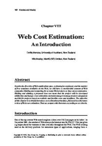
In the original exploration process in [1], an important architecture parameter was fixed before the exploration process; the latency of function units was given by the user. This approach does not take into account that the latency of a function unit is dependent on the timing requirement, i.e., a unit may require pipelining, which increases the latency, when shorter delay is needed. In a similar fashion, the same unit may have a different structure if delay requirements are different. E.g., simple ripple-carry adder is sufficient for low clock frequencies but higher clock frequencies may require carry-look ahead adders, thus the area and power of the units depends on the delay constraint. In order to automate the selection of the FU latency, we propose that the cost information of several implementations of the same function unit is stored into a cost database together with latency and critical path information. Given a delay constraint, the latency of a function unit can be easily determined. This requires that the clock frequency is not estimated like in [1]. The cycle time is either given by the user or is varied by the exploration process. The implementation of the function unit can be selected with the aid of the cycle time and delay of the component when the inputs and outputs of the function unit are registered, i.e., the critical path determining the delay is from a register to a register. However, the output register is optional, thus it is possible that the critical path in a complete processor is from the input register through the logic of the function unit and the interconnection to the input register of another function unit. In such a case, the interconnection delay has to be taken into account when determining whether the component fulfills the given timing constraints or not. The proposed design space exploration process is illustrated in Fig. 3. The inputs of the exploration process are the unscheduled code of the given application, a set of processor components (resources), and the cost database. In each iteration, a target architecture is formed by selecting a set of resources. The architectural parameters that are related to the implementation, such as latency, are obtained from the cost database. The given application is then scheduled onto the target architecture and the parallel code is simulated. Simulation results are finally used to estimate the cost of executing the parallel code on the architecture. Each evaluated target architecture is stored with its cost and performance statistics as one design point in the design space.
Application in HLL
Compiler Front-End Cost Database area, energy, delay
Maximum Resource Set
Sequential Code
Resource Selection Design Point #i (Machine+Statistics)
Machine Description#i Statistics#i utilizations#i, area#i, clock period#i, cycles#i, energy#i
Cost Estimation
Mapper & Scheduler Parallel Code #i
cycles#i, utilizations#i
Simulator Design Space Exploration
Fig. 3. Principal flow diagram of the proposed design space exploration process. HLL: High-level language.
3.2
Technology Characterization
Implementation-specific data about the resources is stored in the cost database. These data can be obtained by running logic synthesis tools and hardware simulators and analyzing the results. This process, called characterization, can be automated and performed off line, since the same cost database can be shared by several exploration runs, with different applications and initial architectures. The hardware description of each function unit is stored in libraries. Those descriptions are needed during the processor generation phase. During the characterization phase, a block is synthesized with varying synthesis constraints and simulated. The implementation data is obtained from the report files. Each type of hardware resource, i.e., function units, register files, and interconnections, is characterized by a specific set of properties, as shown in Table 1. The database contains also an entry for the control logic. In addition, certain metrics may consist of several values for each entry. 3.3
Area Estimation
The total area of the target architecture is obtained as the sum of the area of each hardware resource, i.e., area of function units, register files, interconnection, and control unit. The area of a particular function unit and register file is obtained by querying the corresponding entry from the database. If an equal match does not exist in the database, the closest possible database entries are used for estimating the area. The area estimation of interconnect is obtained with a slightly different approach. The interconnect consists of sockets, i.e., connections of a port to buses, as illustrated in
Table 1. Properties characterizing the hardware resources
Resource
Characterized by
Function Unit
operations, word width, operation delay (critical path), output delay (delay from last register to output), latency, no. pipeline stages, pipeline control discipline, no. input ports, no. output ports
Register File
no. words, word width, delay, no. read ports, no. write ports
Interconnect
fanin, fanout, word width, delay
Control Unit
density of the interconnection network
Fig. 4. In our case, busses are realized with the aid of one-directional bit lines instead of tristate buses as in [1]. The input and output sockets contain AND gates and multiplexers, respectively. The actual bus contains an OR gate, thus the area estimate is obtained by summing the area estimates of those components from the cost database. 3.4
Energy Estimation
The estimate of the energy consumed by a resource cannot be obtained directly from the database but it must be linearly approximated from the utilization, and weighted according to the used cycle time. The energy estimate of a function unit, E FU , is obtained as follows � � � � nctclk FU (1) E = ∑ Ui Ei + Eidle nc − ∑ Ui + Estatic td i i a)
FU0 tdata odata rdata
FU1 tdata odata r1data r2data Bus0 Bus1 Bus2
b)
Socket FU0 rdata Output Socket
Ena
FU1 r1data Output Socket Ena
FU1 r2data Output Socket Ena
FU0 tdata FU0 odata FU1 tdata FU1 odata Input Input Input Input Socket Socket Socket Socket Sel
Sel
Sel
Sel
Bus0
Bus1
Bus2
Fig. 4. Example of TTA processor: (a) logical diagram and (b) principal structure.
where Ei is the dynamic energy per clock of operation i, Eidle is dynamic energy when no operation is executed per clock, Estatic is the energy due to leakage current during time td , td is the delay of critical path, Ui is the number of times the operation i is used, nc is the number of cycles executed in the simulation, and tclk is the clock period. The parameters Ei , Eidle , Estatic , and td are obtained from the cost database, while the parameters Ui and nc are obtained from the instruction set simulation. The clock period tclk is defined during the resource selection. The energy of a register file, E RF , requires a different formulation. An RF is characterised by its number of input and output ports, which has a strong effect on the power consumption. The formula used to compute the energy is � � nctclk RF E = ∑ ∑ ErwUrw + Estatic (2) td r w where Erw is the dynamic energy per clock when r reads and w writes are performed in parallel, Urw is the number of times when r reads and w writes are performed in parallel in simulation, and Estatic is the energy per td due to leakage current of the RF. Again, the parameters Erw , Estatic , and td are obtained from the cost database and Urw and nc are given by the instruction set simulator. The energy consumed by the interconnection is obtained with the same principle as with function units in (1). For estimating the energy of a control unit, E CNT RL , we have used an extremely simple model: E CNT RL = nr (E0 + dEs )
(3)
where nr is the total number of bits in all the registers in the control unit and E0 the dynamic energy per clock cycle of a 1-bit register. The parameter d denotes the density of interconnection network, which is describes how many of all the possible socket connections are used, i.e., d = 1, if all the socket connections are connected (fully connected interconnection). The parameter Es describes the additional energy consumed per clock cycle due to instruction decoding and driving of the control signals to a socket connection.
4 Experimental Results In order to compare the accuracy of the proposed estimation scheme, we characterized a set of function units described in VHDL on a commercial 0.11 µ ASIC technology and created a cost database. We used a number of applications including 8 × 8 discrete cosine transform and Viterbi decoding and selected several target architectures for each application, with varying level of parallelism. The applications were compiled with Move tools onto the target architectures and the Move simulator was used to obtain the run-time statistics. A VHDL description of each target architecture was generated. For each target architecture, the reference area was obtained by synthesizing the design using the Synopsys Design Compiler. The timing constraints used in the synthesis were used as values of requested clock period in the estimations. The energy references
4.00
70
3.50
60
3.00
50
2.50
T=203µsec
uJ
kilogates
80
40
20
1.00
10
0.50
BE BR
CE CR
CNTRL IC RF
1.50
AE AR
T=109µsec
2.00
30
0
T=186µsec
0.00
FU
AE AR
BE BR
CE CR
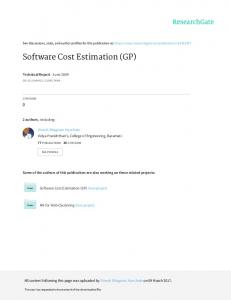
Fig. 5. Experimental area and energy comparisons of three processor architectures executing the same application. Processors A and B run at clock frequency of 100 MHz and processor C at 200 MHz. AE , BE ,CE : Estimates. AR , BR ,CR : References. T : Execution time.
were obtained by performing first gate-level simulation for capturing the switching activity. The activity information was used in the power analysis of the Design Compiler. The simulation was performed by using the binary code generated by the Move tools. An example of experimental results is given in Fig. 5, which shows area and energy of function units (FU), register files (RF), interconnect (IC) and control logic (CNTRL) for one application executed on three different architectures. According to preliminary experiments, the average error in area estimation is 5% and the maximum error is 18.3%. The largest error is in the interconnect and control logic. The error in energy estimation is larger: 10.5% on average and maximum of 34.8%. Again, the largest error is typically in the interconnect and control unit due to the fact that the used models are simple. The speed of the estimation process is mainly dependent on the number of function units and register files. The size of the cost database has also an effect on the estimation speed. In order to have an idea of the estimation speed and its portion of the overall design space exploration process, we measured the time an estimation takes on a Linux work station with 600 MHz Pentium 3 processor. Target architectures ranging from 20– 70 kgates required 1–5 sec while simulation of these (500–2M instruction cycles) took 2–60 seconds. The actual compilation took 2-120 seconds. Therefore, one iteration in the design space exploration, estimation of one processor took 5–180 sec. When those processors are synthesized on a work station with a 3 GHz Pentium 4 processor, the logic synthesis alone takes from 2 hours to 2 days. The power analysis of the synthesized structure with the switching activity capture in simulator requires another 2 hours to 2 days depending on the number of instruction cycles.
5 Conclusions In this paper, we have proposed a cost estimation methodology suited for design space exploration for TTA processors. In addition, we proposed an improved exploration process with tool-assisted selection of pipelining degree for function units of a given
target architecture. Our preliminary comparisons show that the proposed cost estimation process is really quick. Therefore, it is well suited for exploration where hundreds or even thousands of architectures are evaluated. In addition, the experiments show that the area accuracy of the estimation is clearly sufficient for design space exploration. The energy estimation does not perform as well, especially the estimation of interconnect could be improved. However, the energy estimation accuracy is still sufficient for exploration; it allows comparison of different processor architectures.
Acknowledgement This work has been supported in part by the Academy of Finland under project 205743 and The National Technology Agency of Finland under project “Flexible Design Methods for DSP Systems”.
References 1. Corporaal, H., Arnold, M.: Using transport triggered architectures for embedded processor design. Integrated Computer-Aided Eng. 5 (1998) 19–38 2. Corporaal, H.: Microprocessor Architectures: From VLIW to TTA. John Wiley & Sons, Chichester, UK (1997) 3. Jin, H.S., Jang, M.S., Song, J.S., Lee, J.Y., Ki, T.S., Kong, J.T.: Dynamic power estimation using the probabilistic contribution measure (PCM). In: Proc. Int. Symp. Low Power Electronics and Design, San Diego, CA (1999) 279–281 4. Wu, Q., Qiu, Q., Pedram, M., Ding, C.S.: Cycle-accurate macro-models for RT-level power analysis. IEEE T. VLSI 6 (1998) 520–528 5. Ahonen, T., Nurmi, T., Nurmi, J., Isoaho, J.: Block-wise extraction of Rent’s exponents for an extensible processor. In: Proc. IEEE Comput. Soc. Ann. Symp. VLSI, Tampa, FL (2003) 193–199 6. Chang, N., Kim, K., Lee, H.G.: Cycle-accurate measurement and characterization with a case sudy of the ARM7TDMI. IEEE T. VLSI 10 (2002) 146–154 7. Contreras, G., Martonosi, M., Peng, J., Ju, R., Lueh, G.Y.: XTREM: A power simulator for the Intel XScale core. In: Proc. ACM Conf. Language Compilers Tools Embedded Syst., Washington, DC (2004) 115–125 8. Brooks, D., Tiwari, V., Martonosi, M.: Wattch: A framework for architectural-level power analysis and optimizations. In: Proc. Int. Symp. Comput. Arch., Vancouver, BC, Canada (2000) 83–94 9. Vijaykrishnan, N., Kandemir, M., Irwin, M.J., Kim, H.S., Ye, W., Duarte, D.: Evaluating integrated hardware-software optimizations using a unified energy estimation framework. IEEE T. Comput. 52 (2003) 59–76 10. Gerlach, J., Rosenstiel, W.: A scalable methodology for cost estimation in a transformational high-level design space exploration environment. In: Proc. Design, Automation and Test in Europe, Paris, France (1998) 226–231 11. Talarico, C., Rozenblit, J.W., Malhotra, V., Stritter, A.: A new framework for power estimation of embedded systems. IEEE Comput. 38 (2005) 71–78