by Verilog and VHDL, calls for a direct comparison to expose ... software descriptions at different levels of ..... even
Hardware Description Languages Compared: Verilog and SystemC Gianfranco Bonanome Columbia University Department of Computer Science New York, NY Abstract As the complexity of modern digital systems increases, engineers are now more than ever integrating component modeling by means of hardware description languages (HDLs) in the design process. The recent addition of SystemC to an already competitive arena of HDLs dominated by Verilog and VHDL, calls for a direct comparison to expose potential advantages and flaws of this newcomer. This paper presents such differences and similarities, specifically between Verilog and SystemC, in effort to better categorize the scopes of the two languages. Results are based on simulation conducted in both languages, for a model with equal specifications.
Introduction Continuous advances in circuit fabrication technology have augmented chip density, consequently increasing device complexity. This has resulted in a higher degree of design automation and increase in the number of tools available to an integrated chip designer. Recently there has been an incline toward the usage of Hardware Description Languages [3]. The portability of models created with such tools, has made them preferable over their corresponding flow, state and logic diagrams. Various HDLs with diverse properties and objectives have been developed over the years, giving designers a vast selection in the appropriate modeling instrument. SystemC presents a new approach to the concept of HDLs, as it combines hardware and software descriptions at different levels of abstraction, by extending C++ with a new library.
This library encompasses all of the necessary components required to transform C++ into a hardware description language. Such additions include constructs for concurrency, time notion, communication, reactivity and hardware data types. As described by Edwards [1], VLSI verification involves an initial simulation done in C or C++, usually for proof of concept purposes, followed by translation into an HDL, simulation of the model, applying appropriate corrections, hardware synthesization and further iterative refinement. SystemC is able to shorten this process by combining the first two steps. Consequently, this also decreases time to market for a manufacturer. Generally a comparison between two computer languages is based on the number of lines of code and execution time required to achieve a specific task, using the two languages. A number of additional parameters can be observed, such as features, existence or absence of constructs that facilitate coding, availability of optimization techniques, as well as others. These criteria vary slightly when attempting to compare two HDLs. For instance, HDLs need to have time-handling constructs, unlike most other computer languages. Comparable “building blocks” may synthesize into different circuitry, depending on the language’s standard. Other points utilized as a basis for comparison include: efficiency of methods and language constructs, signal behavior description, scheduling semantics and ease of implementation. In this paper I will be comparing different aspects between the Verilog [2] and SystemC [4] HDLs, according to the measures mentioned above. The code that will be used to base this comparison implements an alarm clock controller.
Related work Previous work comparing two or more HDLs is limited to a few papers, usually regarding VHDL and Verilog. This is mainly due to the fact that SystemC is a latecomer to this field, but also because it is merely an extension of an already existing language. Douglas Smith wrote a tutorial [5] in which he compares VHDL and Verilog. Smith also describes the range of modeling capacity possessed by the two languages, exposing VHDL’s lower modeling limit: gate level. Interestingly enough, Verilog is one of the few HDLs capable of modeling down to transistor level. Few additional papers dealing with two or more HDLs exist, but are generally not meant to bring forth comparison issues, rather to present co-design techniques such as Agliada [8]. In his paper on co-simulation of VHDL and SystemC, Agliada introduces a method to homogenize the system descriptions in order to simulate them together. This approach calls for a VHDL to SystemC translator. In describing such a tool, it is unavoidable to compare the two languages, even if not in detail.
Fundamental differences in constructs Both Verilog and SystemC utilize modules as design entities While Verilog has the module keyword build in, SystemC needs to call a construct named sc_module() to declare the body of the device at task. The difference in module declaration syntax can be seen below in figure 1.
Verilog module runner(port names); //port sizes and direction //body endmodule
SystemC SC_MODULE(Runner) { //ports sizes and direction //body }; //member functions
Figure 1. Component declaration syntax.
Although Verilog may appear slightly more concise at first, it should be pointed out that the former requires ports to be listed once in the module declaration line, and again immediately
after, to specify their sizes. SystemC accomplishes this in one step, but at its own can declare a function separately from its body, as in C. This property of the language can also be viewed as an advantage, since a module can therefore call several different processes. Verilog is only able to carry out a process if found within a module, which signifies having to write a module for every process that needs to be called by external modules. The absence of a high level construct that replicates structure can often lead into writing code that may seem repetitive, or difficult to optimize. When modeling a process in Verilog, common practice is to have an always construct around the body of the function to be evaluated. In SystemC, the functions are written as members of the module class being designed, allowing the designer to more easily integrate additional functionality in the same design. Timing mechanisms vary extensively between Verilog and SystemC. The later has a built-in clocking mechanism, where such a device and its output signal wave can be described using the sc_clock() construct. Instead, Verilog uses a more general way to create a clock: by defining it as a module. Although this technique may appear inefficient, it is actually more natural for a beginning designer, since no new constructs need to be learned. Figure 2 below, illustrates this point. Verilog module m555 (clock); output clock; reg clock; initial #5 clock = 1; always #50 clock = ~clock; endmodule
SystemC sc_clock m555("m555", 20, 0.5, 5, true);
Figure 2. Clock declaration syntax.
SystemC allows for three types of processes to be utilized in the description of a model: methods, threads and synchronized threads. According to the SystemC User’s Guide [4], methods execute when changes occur in signals found in their sensitivity list. Upon termination, a method returns control to the simulation kernel. Threads behave similarly as methods, but they may also be suspended and reactivated at the
occurrence of a specified event. As Edwards [1] points out, hardware does not exhibit this behavior, but such processes can be useful when designing a test bench. Synchronous threads are a special case of threads, where triggering takes place at a specific edge of a signal. The scheduling of all three process types takes place at the bottom portion of a SystemC model, by using the sc_ctor() macro (SystemC constructor). In modeling an alarm clock controller, such a constructor was called for the tick process of type method:
wire or tri wor or trior wand or triand tri0 tri1 supply0 supply1 trireg
Simple interconnecting wire Wired outputs OR together Wired outputs AND together Pulls down when tri-stated Pulls up when tri-stated Constant logic 0 (supply strength) Constant logic 1 (supply strength) Stores last value when tri-stated (capacitance strength)
Here the condition may be a signal or an event, in which case the identifier will be found between parentheses. By this token, a function can also be edge-triggered:
In order to support modeling at different levels of abstraction, from the functional to the registertransfer level, as well as to support software, SystemC provides programmers with a rich set of signal types. This is different from languages like Verilog that only support bit-vectors as types. SystemC can implement both two-valued and four-valued signal types, which add practicality to a simulation. SystemC’s set of data types is enhanced to support multiple design domains and abstraction levels. The fixed precision types allow for fast simulation. The arbitrary precision types can be used for computations with large numbers and to model large busses. Such types do not have a limitation in size. In addition, this HDL provides a large selection of overloaded operators, quantization and overflow modes, as well as type conversion mechanisms. SystemC, extends C++ types by utilizing the following signal definition syntax:
always @ ( posedge clock )
sc_signal < base_type > signal_name;
As strongly-typed languages, both Verilog and SystemC support signals as well as variables. They do differ in the built-in types available to the user. Verilog subdivides its data types into two main categories: registers and nets. A register type involves storage and consists of the following variants:
where base_type corresponds to one of C++’s base types, such as integer, real, char, etc. Likewise, ports are declared with the same syntax, but utilize the identifiers sc_in, sc_out or sc_inout. As in C or C++, a SystemC description can include user-defined libraries containing functions and data structures, to employ throughout a program. Verilog offers no such reusability feature, which in certain cases can be a drawback. This is mainly due to the language’s interpretive nature.
sc_ctor ( Runner ) { sc_method ( tick ); sensitive_pos ( clock ); } where Runner is the name of the sc_module that owns the tick process. Verilog per se does not differentiate among processes, but allows flexibility to mimic the behavior found in the three scenarios described above. This is achieved by means of timingoriented constructs such as: always @ ( condition )
reg integer time real
unsigned variable of any bit size signed 32-bit variable unsigned 64-bit variable double-precision floating point
Nets (or wires) are of a larger variety:
Creating Descriptions Intuitively, Verilog can be very efficient in structural designs, as the language possesses moderately uncomplicated port-mapping and module instantiation techniques. Switching between layers of abstraction can be confusing at times, since no dedicated constructs exist to aid the modeling of larger designs. For this reason, the structure of the description may appear the same throughout, regardless of component hierarchy. SystemC introduces a bit more discipline in large system modeling, by means of special constructs. The ability of declaring a sc_main() routine that manages all of the other modules, clocking and data transfer schemes, is a major advantage. This also facilitates the debugging process of the very same descriptions. At the same time, its object-oriented sequential origins make SystemC suitable for behavioral designs. This introduces a new concept in system design: the co-simulation of a piece of hardware and its embedded software, using the same language. It is now possible to implement, for example, a controller and its driver all under the same roof. Beginners will find Verilog easier to learn, due to its generalized syntax. It also does not require the user to be familiar with other languages that the HDL was based on, as is the case with SystemC and C++.
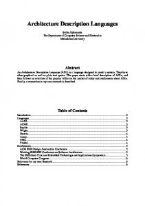
Simulation semantics Verilog and SystemC adopt different simulation semantics. Verilog utilizes an eventdriven scheduler, which obeys the rules illustrated by the graph in figure 3. Here we see nested loops executing in zero-time, which translates directly into slower execution times during simulation, than those of a cycle-based scheduler. Although proven competent, such a set of semantics is at times a drawback on performance, as several actions are expected to take place in each clock cycle.
while there are events
Advance Time
while there are active events
Inactive events?
Activate them
non-blocking assign events
Activate them
Activate monitoring events
while there are active events update the changed object; Update event?
schedule any evaluation events for sensitive processes;
process evaluation event;
Figure 3. Verilog Simulation Semantics.
In comparison, SystemC’s cycle-based simulation semantics are much simpler, as overhead for different types of events is eliminated. Overall scheduling is more efficient, as timing information is done away with. The graph adaptation from Mueller [7] illustrates below:
Clock Update
Advance Time
Update outputs of newly triggered sync. processes
Execute all async. processes whose inputs just changed
Execute all triggered sync. processes
Figure 4. SystemC Simulation Semantics.
Language Determinism The Verilog simulation model pictured above guarantees a certain level of determinism over the scheduling order. Statements located within a begin-end block are guaranteed to execute sequentially in the order listed inside such a begin-end block. Although a process may very well suspend itself at a certain event and later regain control, its statements will still be executed in the order listed within the begin-end block. Non-blocking assignments will always be performed in the order that the statements were to be executed. For example: initial begin A