data which modulates the unique spreading code assigned to that user, which .... the detection algorithms for the correct recovery of the information bits from the.
Proc. SPIE Conf. on Advanced Signal Processing: Algorithms, Architectures, and Implementations VIII, Vol. 3461, San Diego, CA, July 1998.
Hardware design issues for a mobile unit for next generation CDMA systems Suman Das Chaitali Sengupta Joseph R. Cavallaro Electrical and Computer Engineering Department, Rice University, MS 366, 6100 South Main Street. Houston, TX 77005-1892. (suman,chaitali,cavallar)@rice.edu
ABSTRACT
This paper addresses hardware design issues of a mobile receiver for future generation direct sequence CDMA wireless communication systems. In the design of a mobile unit, xed-point hardware is an attractive alternative because of increased speed, reduced power consumption, and reduced hardware costs. In this paper, we focus on the xed-point implementation of `blind' detection and channel estimation schemes that do not require knowledge of spreading codes of the other users. The error pattern of the `blind' algorithms, wordlength requirements, and the operation count required for implementation of such algorithms are evaluated. Our results show that the blind maximum likelihood channel estimation along with the blind MMSE detection algorithm can achieve approximately ve times improvement in performance over the conventional correlator based receivers. These newer algorithms require slightly higher wordlength but similar computational complexity. Keywords: CDMA, forward link, hardware design, xed-point
1. INTRODUCTION
Direct Sequence Code Division Multiple Access (DS-CDMA) has recently emerged as a viable protocol for digital cellular communications, with the deployment of CDMA systems based on the IS-95 standard. With the acceptance of wideband CDMA for the third generation cellular systems, it is necessary to look for e�cient implementation techniques for the more sophisticated, but more complex algorithms that may be used in such systems. In a CDMA communication system, a communication channel with a given bandwidth is accessed by multiple users simultaneously. The di�erent mobile users are distinguished by the unique spreading code assigned to each user. In the reverse link, the CDMA signal transmitted by any given user towards the base station, consists of that user's data which modulates the unique spreading code assigned to that user, which in turn modulates a carrier using any well-known modulation scheme such as binary phase shift keying (BPSK). The frequency of this carrier is identical for all users. In the forward link, the transmitting base station modulates the data transmitted to each user with the user's spreading code. The mobile handset receives a superposition of the signals for all the users transmitted by the base station. As the base station uses a common transmit clock for the signals of all the users, these signals are synchronous with respect to each other and have the same power.1 However, the channel will introduce an arbitrary delay and arbitrary attenuation factor into this composite signal. This delay and attenuation factor must be estimated by the receiver for e�cient detection of the user's bits. The major part of the research on the advanced receiver structures for CDMA has focused on the reverse link, where the goal has been to detect the information bits of all the users simultaneously, using multiuser techniques.2 Implementation issues in the reverse link such as xed-point error analysis has been studied quite extensively.3 It has often been assumed that the forward link is just a simpler version of the reverse link problem and the unique features of the forward link have not been evaluated from the implementation point of view. This paper contends that the problem of designing algorithms and hardware for the forward link is not just a special case of the same problem in the reverse link, with the simpli cations due to synchronous transmission and equal power. This is because one needs to assume that the mobile receiver has limited information as well as resources, as compared to the base station receiver. To simplify the mobile receiver algorithms and hence the hardware size, power, and cost, we investigate `blind' algorithms for channel estimation and detection for the forward link. That is, the algorithms should assume that the
receiver has knowledge of its own spreading code only, and not of any of the other users. This criteria is also necessary for reasons of security and privacy. A number of `blind' algorithms have been proposed in the literature. However these algorithms have not been evaluated speci cally for the forward link, with the unique feature of synchronous users with equal powers. The correlator based channel estimation and detection algorithms used in current CDMA systems are single-user techniques, and hence are `blind' techniques. Such techniques treat the interfering users and the background noise as additive white gaussian noise (AWGN). We evaluate these techniques in this paper as well as two more sophisticated algorithms4,5 which account for the interfering users in some way, instead of simply treating the interference as AWGN. Implementation aspects of the forward link have been studied before6 from the point of view of low power VLSI implementation of the correlator based techniques. The performance of any other more complex `blind' algorithms have not been evaluated in that paper.6 In the current paper, we focus on the performance evaluation and implementation issues related to the more complex algorithms.4,5 In order to reduce hardware size and cost of the mobile handset, xed-point implementation is an attractive alternative. Fixed-point hardware3 has some additional advantages in terms of increased speed, reduced power consumption and reduced hardware cost. However, due to the xed wordlength of the hardware, a xed-point implementation will also incur errors7 due to quantization and over ow. In this paper, we evaluate the error pattern of these algorithms when implemented on xed-point hardware. We also report the instruction count of the algorithms in terms of the various system parameters. The paper is organized as follows. Section 2 describes the system model for the CDMA forward link, based on the above assumptions. In Section 3 we present a brief description of the various `blind' algorithms. Section 4 evaluates the performance of these algorithms and Section 5 presents the operation counts. The evaluation of the xed-point implementation is presented in Section 6.
2. SYSTEM MODEL
In this section we develop a system model that captures the behavior of the transmitted and received signals in the forward link of a CDMA system. We assume a K -user narrow band direct sequence CDMA system with BPSK modulation with each transmitted signal selected from a binary alphabet and limited to [0; T ], where T is the symbol period. The complex baseband representation8 of the signal transmitted by the transmitter at the base station consists of the superposition of the signals sent by the base station to all the users. This signal s(t) can be represented as: s(t) =
X K
sk (t)
sk (t) =
p X N
P
bk;ick (t
iT ) ;
(1)
i=1
k =1
where P is the transmitted power which is the same for all the users, b 2 f+1; 1g is the ith transmitted bit of the k user and c (t) is the spreading waveform. The parameter N denotes the number of bits being considered. The spreading is composed of N chips and if we assume BPSK for the spreading modulation we have P c 1 waveform c (t) = c �( t nT ), where c 2 f+1; 1g and the chip pulse waveform �(t) is a rectangular pulse of =0 duration T . We will assume that the extent of the spreading code is one bit period and hence we have T = N T . The channel between the transmitter at the base station and the mobile receiver introduces an arbitrary delay and attenuation on the transmitted signal. Hence, the signal received by any of the K mobile users is: k;i
th
k
c
N
k
n
k;n
c
k;n
c
c
r(t) = ws(t
� ) + � (t)
c
(2)
where w is the arbitrary attenuation factor and � is the arbitrary delay. These two parameters are unknown and time varying and need to be estimated at the receiver to facilitate detection of the transmitted bits. The noise component � (t) is assumed to be gaussian with zero-mean and double-sided spectral density of N0=2. It should be noted here that (2) accounts for the fact that the signals for all the users remain synchronous with respect to each other and experience the same channel delay and attenuation.
As discussed in Section 1, to ensure privacy and reduce cost, the receiver in the handset only knows the spreading code of its own user. Hence, it is necessary at this stage to separate the contribution of the user of interest and the remaining interfering users: r(t) = ws1 (t
�) + w
X K
sk (t
� ) + � (t):
(3)
k =2
In the forward link, one can think of the interfering users as being treated as one single interference term, as the structure of that interference is unknown. Let us say that this interference plus the additive white gaussian noise is I (t): r(t) = ws1 (t
� ) + I (t):
(4)
In the next section, `blind' algorithms for channel estimation and detection will be described, based on this model.
3. BLIND ALGORITHMS FOR CHANNEL ESTIMATION AND DETECTION
In this section, we identify a few `blind' algorithms for channel estimation and detection which have low computational complexity and perform well for a wide range of system parameters. These algorithms assume the knowledge of the spreading code of the user of interest only.
3.1. CHANNEL ESTIMATION
The goal of channel estimation is to nd the arbitrary delay and attenuation introduced by the wireless channel. Such an estimate is required by the detection algorithms for the correct recovery of the information bits from the received signal.
3.1.1. Sliding correlator
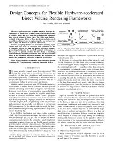
The simplest option for blind channel estimation is the sliding correlator,9 used in current systems. The received signal 4 is correlated with locally generated copies of the code at the receiver with delays spaced every one-half (or smaller fraction) of a chip. The delay corresponding to the largest output is the estimated delay. The process is illustrated in Figure 1. The gure shows that if the delay is to be estimated to the closest half of a chip, a bank of 2N correlators will be required. The number of correlators will increase if a more accurate estimate is desired. c
c(t)
Received signal r(t)
c o Integrate m & dump p a x r c(t-(2N c-1)T c) a t o x r
. . . . . .
x c(t-jTc)
Figure 1. Sliding correlator
3.1.2. Maximum likelihood algorithm (ML)
The sliding correlator treats the interfering users as AWGN. This is not strictly true and limits the performance of such a channel estimator. Recently a more sophisticated algorithm4 has been proposed which models the interfering users as colored noise. In this section we present a brief description of this algorithm. The continuous time signal r(t) at the receiver is discretized by sampling the output of a chip-matched lter at the chip rate. The observation vector ri at time i is then formed by collecting N such outputs together. Since the arbitrary time delay introduced by the channel is not known by the receiver at this stage, the contribution of the signal for the user of interest to the observation vector can be viewed as a linear combination of two signal vectors, that is two components for each user due to the past and current bits10,11 as shown in Figure 2. In the example shown in the gure N = 7 and the spreading code is [1 -1 1 1 -1 1 1]. The (i 1) and the i bits have the values +1 and -1 respectively. c
th
C
th
delay τ N cTc
chip Tc
time b i-1 = (+1) ri
bi = (-1)
R
L
Figure 2. System model - contribution of signal from the rst user to the observation vector We can now write ri as :
ri = UHbi + Ii ;
Ii � N (0; R)
(5) where U is the matrix of the \signal vectors" which depend only on the known spreading code of the user. H is the channel impulse response matrix and is a function of the channel delay and amplitude. The vector bi contains the user's previous and current data bits, and R is the unknown noise covariance. The N � 2N matrix U is composed of the spreading code of the user of interest, shifted by all possible integer delays, and corresponding to the two consecutive bits (Figure 2). Hence, U is expressed in terms of its `left' and `right' components, denoted by the superscripts L and R. The `left' component refers to the left part of the spreading code and `right' is the corresponding right part. U = [U U ] (6) c
c
R k
U = [ckR [0] � � � ckR [Nc 1]]; (R)
(
)
(
UkL = [ckL [0] � � � ckL [Nc 1]];
)
( )
k
where, the shifted spreading codes are: cRk[q] = [c c � � � c k;N
( )
1
0 � � � 0]
T
;
k;0
k;Nc
q
1
T
If T is the chip period, let � =T composed of the channel parameters between the base station and the mobile and is expressed as: 2 0 3 66 .. 77 66 . 77 H = diag(h; h); h = 66 w(1w ) 77 q(q entry + 1) 66 . 77 4 .. 5 0 c
c
(7)
( )
cLk [q] = [0 � � � 0 c � � � c ] (8) = q + , q 2 f0; 1; � � � ; N 1g; 2 [0; 1). The matrix H of size 2N � 2 is k;Nc
q
L k
c
th
th
c
(9)
The channel delay and attenuation captured in H may be estimated from observations ri , a known sequence of transmitted bits (preamble), and the knowledge of the spreading code of the user, using a maximum likelihood technique.4 A preamble is a known sequence of bits inserted at regular intervals in a frame. A frame is a structured collection of bits that de nes the format of data transmission. It should be noted that an alternative to using a preamble for channel estimation is to use a pilot channel. However the pilot channel requires extra bandwidth. Moreover the preamble is essential in the case when the user data is transmitted with a di�erent antenna pattern than the pilot channel.12 Given W observations r1 ; r2; � � � ; rWs , the joint conditional probability density function of r1 ; r2; � � � ; rWs is: s
p(r1 ; r2; � � � ; rWs jH; b) =
1
�(Nc Ws ) jRjWs
exp
( X Ws
UHbi)� R 1(ri
(ri
i=1
UHbi )
)
(10)
:
The maximum likelihood algorithm maximizes the above probability with respect to f�; wg or fHg. The interference provided by the other users plus the additive white gaussian noise is modeled as colored noise, the correlation matrix of which is estimated in the algorithm. Once the matrix H is estimated, the individual parameters, that is the delay and the attenuation factor, can be extracted from H by a least squares t of H to the parametric channel model (9).
3.2. BLIND DETECTION ALGORITHMS
The detection procedure uses the channel parameters obtained from the channel estimation step. The blind detection algorithms are assumed to have the knowledge of the delays and the signature waveform of the user of interest only. The chip matched lter output of the received signal spanning the j bit interval can be expressed as the N length vector th
rj = w
X K
c
ck b + � ; k;j
j
k =1
where the aim is to estimate the j information bit of the rst user b1 . th
;j
3.2.1. Code-matched lter
Similar to the sliding correlator technique, the matched lter (MF) technique is the simplest way of estimating the information bits using the minimum amount of information and processing. The success of the lter hinges on the orthogonality of the signature waveforms assigned to individual users. The received chip matched lter output is correlated with a locally generated copy of the signature waveform and the output of the integrator is dumped at the end of each bit interval. A nal decision about the information bit is made by passing the output of the matched lter through a sign detector.
3.2.2. Blind MMSE detector
The performance of the matched lter degrades as the number of users in the system, and hence the e�ective multiple access interference (MAI) increases. The blind minimum mean square error (MMSE) detector5 combats the interference resulting from the other users without requiring any further information. The aim of the MMSE detector is to design a lter, F, such that when the received chip matched lter output is processed by this lter the mean square error of the estimate is minimized. Thus F is to be chosen such that E (kFr
p
w P b1 k2)
is minimized. It can be shown that F = c1 + x where x is orthogonal to the user code c1 and thus the minimization process involves nding x to minimize the mean square error. It has been shown5 that minimizing the mean square error is equivalent to nding the lter coe�cients in such a way that the energy at the output of the lter is minimized. Moreover a steepest descent algorithm has been proposed5 to calculate x iteratively. Another attractive property of this algorithm is that it has the same order of computational complexity as the matched lter. In our study we have used this particular implementation of the blind MMSE algorithm.
4. ERROR EVALUATION
In Section 3 a number of existing `blind' algorithms were presented. In previous studies4,5 the performance of these algorithms in terms in terms of sensitivity to system parameters such as signal-to-noise ratio (SNR) and MAI has been studied in isolation. For example, the evaluation of the detection algorithms assumed perfect channel knowledge or the channel estimation algorithms have been evaluated in terms of error in the estimate only and not nal bit error rate (BER). However none of the existing studies analyze the interaction between the various `blind' algorithms for channel estimation and detection, especially in the context of the forward link. In this section, we evaluate the performance of the algorithms with respect to key system parameters as well as sensitivity of the detection algorithms to errors in the estimation of the channel parameters. In a subsequent section, we will also study the xed-point wordlength requirements as well as the operation counts for the algorithms. We determine the sensitivity of the algorithms to variations in two primary system parameters, the background (SNR), and the number of users, K . It should be noted that both of these system parameters increase the interference term in (4). Hence, the performance of the algorithms is expected to become worse as the SNR is decreased or the number of users is increased. 0.11 RMSE in delay estimate
1
Prob. of acq.
0.9 0.8 0.7 Correlator ML
0.6 0.5
5
10
15 20 Number of users
25
0.1 0.09 0.08 0.07
0.05
30
Correlator ML
0.06 5
10
15 20 Number of users
25
30
Figure 3. Probability of acquisition and RMSE in delay estimate using both channel estimation algorithms (versus number of users). (N = 31; SN R = 10dB ) c
Figures 3 and 4 show the performance of the channel estimation algorithms. The metrics used to evaluate the performance are the probability of acquisition and the root-mean-square-error (RMSE) in the delay estimate. Here, acquisition is de ned as the following condition: (j� �^j < pT ) c
(11)
where, 0 < p < 1 is the fraction of a chip which de nes the acceptable limit on the error in the delay estimate. In Figures 3 and 4, p is chosen to be 0:2 for reasons discussed later in the section. The RMSE in the delay estimate is determined, conditioned on the fact that acquisition has occurred. It is interesting to note in Figure 3, that the probability of acquisition for the sliding correlator is greater than the maximum likelihood algorithm when the interference is low. Figure 4 shows that for K = 15, the two algorithms perform very similarly as the SNR is varied. The similarity between the algorithms at K = 15 is also evident in Figure 3. However, as the SNR is increased, we can notice a slight increase in performance of the maximum likelihood algorithm. This is because the performance of the sliding correlator does not improve, even when the SNR is higher, due to the high interference from the 14 other users. However the ML algorithm is more successful in combating the higher interference. In terms of RMSE, the maximum likelihood algorithm always outperforms the sliding correlator.
0.11 RMSE in delay estimate
1
Prob. of acq.
0.9 0.8 Correlator ML
0.7 0.6 0.5
6
8
10
0.1 0.09 0.08 0.07
0.05
12
Correlator ML
0.06 6
8
SNR
10
12
SNR
Figure 4. Probability of acquisition and RMSE in delay estimate using both channel estimation algorithms (versus SNR). (N = 31; K = 15) c
0
0
10
10 blind MMSE MF
−1
−1
BER
10
BER
10
−2
−2
10
10
blind MMSE MF −3
10
−3
6
8
10 SNR (dB)
(a)
12
10
5
10
15 20 25 Number of users
30
(b)
Figure 5. Blind MMSE performance when (a) SNR (K = 15) and (b) the number of users (SN R = 10dB ) is varied Figure 5 shows the performance of the two detection schemes when the SNR and number of users are varied. This initial experiment assumes perfect knowledge of the channel and shows that the BER of the blind MMSE algorithm is consistently better than the matched lter. The two preceding experiments focused on the evaluation of the performance of the channel estimation or detection algorithms, when each of these blocks are studied separately. However in a practical wireless communication system, the detection algorithms must utilize the results of the channel estimation algorithms. Any error in the estimate of the channel parameters will also a�ect the performance of the detection algorithms. In Figure 6(a) we report the sensitivity of the detection algorithms towards channel estimation errors. It is evident that the blind MMSE algorithm is more sensitive towards delay estimation errors than the sliding correlator. Also, to get acceptable results,
0
1
Prob of acquisition
10
−1
BER
10
−2
10
blind MMSE MF 0
0.8 0.7
ML Correlator
0.6
−3
10
0.9
0.2 0.4 0.6 0.8 Error in delay estimate (chips)
1
0.5
0
(a)
0.2 0.4 0.6 0.8 Allowed estimation error (chips)
1
(b)
Figure 6. (a) Sensitivity of detection algorithms towards channel estimation errors (b) Distribution of error of channel estimation algorithms
the error in the estimate of the delays should be quite close to zero and de nitely less than 0:2T . This is our reason for choosing 0:2T to be the threshold error in the delay estimate for acquisition to have acquired in Figures 3 and 4 A natural extension to the experiment just described would be an analysis of the distribution of the error in the delay estimate, calculated using both channel estimation algorithms. This is shown in Figure 6(b). In this gure, the probability of acquisition is shown versus the allowed error in the delay estimate at which acquisition occurs, that is, p in (11). In other words, this plot is the cumulative distribution function (c.d.f.) of the error in the delay estimate, from both channel estimation algorithms. The gure shows that for both algorithms, the c.d.f. curve almost attens out after 0:2T , which make both algorithms suitable candidates for use with the blind MMSE and matched lter detection schemes. c
c
c
5. OPERATION COUNT
In this section, we will estimate the number of operations required by each of the algorithms in terms of various parameters related to the system as well as the algorithms. We will use the parameters shown in Table 1 to estimate the operation counts. The operation counts are listed in Table 2 and are derived from a close analysis of the various steps in the channel estimation and detection algorithms.
Table 1. Notation Symbol
K Nc (= T =Tc ) Ws fTc
De nition No. of users Spreading code size Window size for channel estimation algorithms Granularity of sliding correlator
For the channel estimation algorithms, the estimate in Table 2 refers to the number of operations required to calculate each channel estimate. In addition, for the maximum likelihood algorithm, one would have to estimate the covariance of the colored noise whenever the interference characteristics change. For example, this calculation may be done once for every frame with the assumption that the interference structure remains constant for the frame
Table 2. Operation count of the blind algorithms Processing Add/Sub Mult Sqrt Maximum 2N W + 10N + N 2 2N W + 10N + N 2 1 Likelihood Sliding N 2 fW N 2fW Correlator Matched N N Filter blind 5N 4N MMSE c
s
c
c
c
s
s
c
c
s
c
c
c
c
c
c
duration. This would also be consistent with the typical design in which the preamble is sent at the beginning of each frame being transmitted. This extra computation to estimate the colored noise covariance will require N 2 W +4W +2N 2 +2N 3 operations. However, without this extra computation, the maximum likelihood algorithm requires less computation than the correlator. For the detection algorithms we provide the operations required to process each information bit. As we have mentioned before, the order of the complexity of the blind MMSE detector is the same as that of the matched lter. c
s
s
c
c
6. FIXED POINT IMPLEMENTATION
In this section, we evaluate the error due to the xed-point implementation of the algorithms being discussed. Any xed-point number can be represented with a xed l bits for the integer part and l bits for the fractional part (Figure 7). The dynamic range of the problem determines l . For our problem, appropriate normalization of the data can eliminate the need for the integer part, l . However l is determined by the precision requirement of the algorithm and requires more careful analysis. In this section, we estimate l through extensive xed-point simulations of the algorithms. In the simulator, all the arithmetic operations are assumed to have the same input and output wordlength of l bits. The simulator has been written in C++, using object-oriented programming techniques. i
i
i
l i bits Integer part
l bits Decimal point (fixed)
Fractional part
Figure 7. Fixed-point representation It should be noted that the simulations in this section assume an input wordlength of l bits, irrespective of the range and precision limits of the analog-to-digital converter used. This assumption was made to study the e�ects of a l bit datapath, irrespective of any constraint posed by the A/D converter. This assumption may slightly favor our results at higher wordlengths. Figure 8(a) shows the performance of the channel estimation algorithms as the xed-point wordlength is varied. Both algorithms require about 16 bit wordlength to reach their performance limit, for the chosen set of system parameters. Figure 8(b) studies the sensitivity of the detection algorithms to quantization error due to the xed point implementation. In this simulation we have assumed that the detector has perfect knowledge of the delays. The matched lter requires a small wordlength of about 8 bits to achieve BER close to its limit. The oating-point performance limit of the blind MMSE algorithm is not reached for wordlengths less than 16 bits. However, even for smaller wordlengths, the blind MMSE algorithm outperforms the matched lter.
−1
1
10
0.6 BER
Prob. of acq
0.8
0.4 Correlator ML
0.2 0
blind MMSE MF
−2
0
10
20 30 Number of bits
40
10
0
(a)
10
20 30 Number of bits
40
(b)
Figure 8. Fixed-point performance of (a) Channel estimation algorithms and (b) detection algorithms with perfect channel knowledge (N = 31; K = 15; SN R = 10dB ) c
Next, we assume that the channel parameters are estimated using the two channel estimation algorithms implemented in oating-point, while the detection algorithm is implemented in xed-point. The motivation behind this experiment is to determine the limit which is the best we can hope to achieve when both channel estimation and detection are performed in xed-point. The results are shown in Figure 9. Again, the blind MMSE performs much better than the matched lter for both sources of channel estimates. However the matched lter requires only about 8 bit wordlength to reach its limit, whereas the blind MMSE requires 16 bits. Also, when the delay estimate is from the maximum likelihood algorithm, the performance is better than when the sliding correlator is used. −1
10
BER
ML+MMSE ML+MF Correlator+MMSE Correlator+MF
−2
10
0
10 20 30 Fixed point accuracy
40
Figure 9. Fixed-point performance of detection algorithms with oating-point delay estimates. (N = 31; K = 15; SN R = 10dB )
c
Lastly, we simulate all four algorithms in xed-point as shown in Figure 10. Again, we can conclude that to achieve best performance we will need 16 bit xed-point hardware. As expected, the best performance is o�ered by the combination of maximum likelihood delay estimation and blind MMSE, followed by sliding correlator and blind MMSE. −1
10
BER
ML+MMSE ML+MF Correlator+MMSE Correlator+MF
−2
10
0
10 20 30 Fixed point accuracy
40
Figure 10. Fixed-point performance of channel estimation as well as detection algorithms. (N = 31; K = c
15; SN R = 10dB )
7. CONCLUSION
In this paper, we have identi ed and evaluated certain issues related to the design of hardware for the mobile handset for future generation CDMA systems. We conclude that at comparable computation costs, it is possible to use more sophisticated channel estimation and detection algorithms, than the correlator based techniques used in current systems. The new algorithms provide approximately ve times improvement in performance. However the new algorithms will require a larger wordlength of 16 bits for e�cient xed-point implementation. The state-of-the-art xed-point DSP processors typically support 16-32 bit operations and so the wordlength requirement may be easily met.
8. ACKNOWLEDGMENTS
This work was supported by Nokia Inc., by the Texas Advanced Technology Program under grants 1995-#003604-049 and 1997-#003604-044, and by NSF under grants NCR-9506681 and CDA-9617383.
REFERENCES
1. R. Kohno, R. Meidan, and L. B. Milsten, \Spread Spectrum Access Methods for Wireless Communications," IEEE Communications Magazine , pp. 58{67, 1995. 2. S. Moshavi, \Multi-User Detection for DS-CDMA Communications," IEEE Communications Magazine , pp. 124{136, Oct. 1996. 3. C. Sengupta, S. Das, J. R. Cavallaro, and B. Aazhang, \Fixed point error analysis of multiuser detection and synchronization algorithms for CDMA communication systems.," Proceedings of the International Conference on Acoustics, Speech, and Signal Processing (ICASSP) , Seattle, May 1998. 4. D. Zheng, J. Li, S. L. Miller, and E. G. Strom, \An e�cient code-timing estimator for DS-CDMA signals," IEEE Trans. Signal Processing 45, pp. 82{89, Jan. 1997.
5. M. Honig, U. Madhow, and S. Verd�u, \Blind Adaptive Multiuser Detection," IEEE Transactions on Information Theory 41, pp. 944{960, July 1995. 6. S. Sheng, R. Allmon, L. Lynn, I. O'Donnell, K. Stone, and R. W. Brodersen, \A Monolithic CMOS Radio System for Wideband CDMA Communications," in Wireless '94 Conference, July 1994. 7. J. H. Wilkinson, The algebraic eigenvalue problem, Oxford University Press, London, 1965. 8. J. G. Proakis, Digital communications, McGraw-Hill, Inc., New York, 1995. 9. R. L. Pickholtz, D. L. Schilling, and L. B. Milstein, \Theory of spread-spectrum communications - A tutorial," IEEE Trans. Communications COM-30, pp. 855{884, May 1982. 10. S. E. Bensley and B. Aazhang, \Subspace-based channel estimation for code division multiple access communication systems," IEEE Trans. Communications 44, pp. 1009{1020, August 1996. 11. C. Sengupta, A. Hottinen, J. R. Cavallaro, and B. Aazhang, \Maximum likelihood multipath channel parameter estimation in CDMA systems," 32nd Annual Conference on Information Sciences and Systems, Princeton , March 1998. 12. F. Ovesjo, E. Dahlman, T. Ojanpera, A. Toskala, and A. Klein, \FRAMES Mulitple Access Mode 2 - Wideband CDMA," in Proceedings IEEE PIMRC, Helsinki, pp. 42{46, Sept. 1997.