Sep 5, 2008 ... SIM548C Hardware Design. Document Title: SIM548C Hardware Design.
Version: 1.01. Date: 2008-05-09. Status: Release. Document Control ...
www.agelectronica.com
www.agelectronica.com
Hardware Design SIM548C_HD_V1.01
www.agelectronica.com
www.agelectronica.com
www.agelectronica.com
www.agelectronica.com
SIM548C Hardware Design
Document Title:
SIM548C Hardware Design
Version:
1.01
Date:
2008-05-09
Status:
Release
Document Control ID:
SIM548C_HD_V1.01
General Notes SIMCom offers this information as a service to its customers, to support application and engineering efforts that use the products designed by SIMCom. The information provided is based upon requirements specifically provided to SIMCom by the customers. SIMCom has not undertaken any independent search for additional relevant information, including any information that may be in the customer’s possession. Furthermore, system validation of this product designed by SIMCom within a larger electronic system remains the responsibility of the customer or the customer’s system integrator. All specifications supplied herein are subject to change. Copyright This document contains proprietary technical information which is the property of SIMCom Limited., copying of this document and giving it to others and the using or communication of the contents thereof, are forbidden without express authority. Offenders are liable to the payment of damages. All rights reserved in the event of grant of a patent or the registration of a utility model or design. All specification supplied herein are subject to change without notice at any time. Copyright © Shanghai SIMCom Wireless Solutions Ltd. 2008
www.agelectronica.com SIM548C_HD_V1.01
2
www.agelectronica.com 09.05.2008
www.agelectronica.com
www.agelectronica.com
SIM548C Hardware Design
Contents Contents ............................................................................................................................................3 Version History.................................................................................................................................9 Scope of the document......................................................................................................................9 1 Introduction..................................................................................................................................10 1.1 Related documents .............................................................................................................10 1.2 Terms and abbreviations ....................................................................................................11 2 Overview......................................................................................................................................14 2.1 Key features .......................................................................................................................15 2.2 Functional diagram.............................................................................................................17 2.3 Evaluation board ................................................................................................................18 3 GSM application interface ...........................................................................................................19 3.1 Pin description....................................................................................................................19 3.2 Operating modes ................................................................................................................21 3.3 Power supply......................................................................................................................23 3.3.1 Power supply pins on the board-to-board connector ................................................25 3.3.2 Minimizing power losses..........................................................................................25 3.3.3 Monitoring power supply .........................................................................................25 3.4 Power up and down scenarios ............................................................................................25 3.4.1 Turn on the GSM part...............................................................................................25 3.4.2 Turn off the GSM part..............................................................................................29 3.4.3 Restart the GSM part using the PWRKEY pin.........................................................32 3.5 Charging interface ..............................................................................................................32 3.5.1 Battery pack characteristics......................................................................................33 3.5.2 Recommended battery pack .....................................................................................34 3.5.3 Implemented charging technique..............................................................................35 3.5.4 Operating modes during charging ............................................................................36 3.5.5 Charger requirements ...............................................................................................38 3.6 Power saving ......................................................................................................................38 3.6.1 Minimum functionality mode...................................................................................38 3.6.2 SLEEP mode (slow clock mode)..............................................................................39 3.6.3 Wake up the GSM part from SLEEP mode..............................................................39 3.7 Summary of state transitions (except SLEEP mode) .........................................................40 3.8 RTC backup........................................................................................................................41 3.9 GSM Serial interface..........................................................................................................44 3.9.1 Function of serial port & debug port supporting ......................................................46 3.9.2 Software upgrade and software debug......................................................................47 3.10 Audio interfaces ...............................................................................................................49 3.10.1 Speaker interface configuration..............................................................................50 3.10.2 Microphone interfaces configuration......................................................................51 3.10.3 Earphone interface configuration ...........................................................................52 3.10.4 Referenced electronic characteristic.......................................................................52
www.agelectronica.com SIM548C_HD_V1.01
3
www.agelectronica.com 09.05.2008
www.agelectronica.com
www.agelectronica.com
SIM548C Hardware Design
3.11 SIM interface....................................................................................................................53 3.11.1 SIM card application ..............................................................................................53 3.11.2 Design considerations for SIM card holder ............................................................55 3.12 LCD interface...................................................................................................................57 3.13 ADC .................................................................................................................................58 3.14 General purpose input & output(GPIO) ...........................................................................58 3.15 Behaviors of the RI line (serial port1 interface only).......................................................58 3.16 Network status indication.................................................................................................60 3.17 Buzzer ..............................................................................................................................60 4 GPS application interface.............................................................................................................62 4.1 Theory of operation............................................................................................................62 4.2 Technical data.....................................................................................................................63 4.3 Pin description....................................................................................................................64 4.4 Turn on the GPS part..........................................................................................................66 4.5 The theory of the GPS RTC circuit ....................................................................................67 4.6 The theory of the RESET Circuit .......................................................................................68 4.7 GPS operation modes .........................................................................................................69 4.8 Serial interface of the GPS part..........................................................................................69 4.9 Start-up procedure ..............................................................................................................70 4.9.1 Coldstart ...................................................................................................................70 4.9.2 Warmstart .................................................................................................................70 4.9.3 Hotstart .....................................................................................................................71 5 Antenna interface .........................................................................................................................72 5.1 GSM Antenna.....................................................................................................................72 5.1.1 GSM Antenna connector ..........................................................................................72 5.1.2 GSM Antenna pad ....................................................................................................72 5.1.3 Module RF output power..........................................................................................74 5.1.4 Module RF receive sensitivity..................................................................................74 5.1.5 Module operating frequencies ..................................................................................74 5.2 GPS Antenna ......................................................................................................................74 5.2.1 GPS Antenna Connection.........................................................................................74 5.2.2 GPS Antenna Choice Consideration ........................................................................75 6 Electrical, reliability and radio characteristics .............................................................................77 6.1 Absolute maximum ratings.................................................................................................77 6.2 Operating temperatures ......................................................................................................77 6.3 Power supply rating............................................................................................................78 6.4 Current consumption ..........................................................................................................79 6.4.1 The current consumption of the GSM part...............................................................79 6.4.2 The current consumption of the GPS part ................................................................80 6.5 Electrostatic discharge........................................................................................................83 7 Mechanics ....................................................................................................................................85 7.1 Mechanical dimensions ......................................................................................................85 7.2 Mounting the module onto the application platform..........................................................86 7.3 Board-to-board connector ..................................................................................................86
www.agelectronica.com SIM548C_HD_V1.01
4
www.agelectronica.com 09.05.2008
www.agelectronica.com
www.agelectronica.com
SIM548C Hardware Design
7.3.1 Mechanical dimensions of the ASTRON 1590060-09T-R.......................................87 7.3.2 Adapter cabling ........................................................................................................88 APPENDIX A: PIN assignment of board-to-board connector........................................................89 APPENDIX B: Reference Circuit with external MCU (GPS standalone application) ...................91 APPENDIX C: Reference Diagram with external MCU (AGPS application)................................92
www.agelectronica.com SIM548C_HD_V1.01
5
www.agelectronica.com 09.05.2008
www.agelectronica.com
www.agelectronica.com
SIM548C Hardware Design
Table Index TABLE 1: RELATED DOCUMENTS...................................................................................................10 TABLE 2: TERMS AND ABBREVIATIONS ....................................................................................... 11 TABLE 3: KEY FEATURES..................................................................................................................15 TABLE 4: CODING SCHEMES AND MAXIMUM NET DATA RATES OVER AIR INTERFACE..17 TABLE 5: BOARD-TO-BOARD CONNECTOR PIN DESCRIPTION ...............................................19 TABLE 6: OVERVIEW OF OPERATING MODES..............................................................................22 TABLE 7: AT COMMANDS USED IN ALARM MODE .....................................................................29 TABLE 8: RECOMMENDED BATTERY PROTECT CIRCUIT PARAMETER.................................34 TABLE 9: SPEC OF RECOMMENDED BATTERY PACK.................................................................34 TABLE 10: OPERATING MODES .......................................................................................................37 TABLE 11: AT COMMAND USUALLY USED IN GHOST MODE ...................................................37 TABLE 12: SUMMARY OF STATE TRANSITIONS...........................................................................40 TABLE 13: PIN DEFINITION OF THE SERIAL INTERFACES ........................................................44 TABLE 14: LOGIC LEVELS OF SERIAL PORTS PINS.....................................................................45 TABLE 15: PIN DEFINITION OF THE AUDIO INTERFACE............................................................49 TABLE 16: MIC INPUT CHARACTERISTICS ...................................................................................52 TABLE 17: SPK OUTPUT CHARACTERISTICS ...............................................................................52 TABLE 18: PIN DEFINITION OF SIM INTERFACE (BOARD-TO-BOARD CONNECTOR) .........54 TABLE 19: PIN DEFINITION (AMPHENOL SIM CARD HOLDER)................................................56 TABLE 20: PIN DEFINITION (MOLEX SIM CARD HOLDER)........................................................57 TABLE 21: PIN DEFINITION OF THE LCD INTERFACE ................................................................57 TABLE 22: ADC SPECIFICATION ......................................................................................................58 TABLE 23: PIN DESCRIPTION OF THE GPIO INTERFACE............................................................58 TABLE 24: BEHAVIOURS OF THE RI LINE......................................................................................58 TABLE 25: WORKING STATE OF THE NETLIGHT .........................................................................60 TABLE 26: BUZZER OUTPUT CHARACTERISTICS .......................................................................61 TABLE 27: PIN DEFINITION ..............................................................................................................64 TABLE 28: CONSOLIDATED PIN CHARACTERISTICS..................................................................66 TABLE 29: GPS OPERATION MODES ...............................................................................................69 TABLE 30: THE GSM PART CONDUCTED RF OUTPUT POWER..................................................74 TABLE 31: CONDUCTED RF RECEIVE SENSITIVITY OF THE GSM PART ................................74 TABLE 32: THE GSM PART OPERATING FREQUENCIES..............................................................74 TABLE 33: ABSOLUTE MAXIMUM RATINGS (GSM PART)..........................................................77 TABLE 34: ABSOLUTE MAXIMUM RATINGS (GPS PART) ...........................................................77 TABLE 35: OPERATING TEMPERATURE.........................................................................................78 TABLE 36: POWER SUPPLY RATING (GSM PART).........................................................................78 TABLE 37: POWER SUPPLY RATING (GPS PART) ..........................................................................79 TABLE 38: CURRENT CONSUMPTION (GSM PART) .....................................................................79 TABLE 39: THE ESD ENDURE STATUE MEASURED TABLE (TEMPERATURE: 25℃, HUMIDITY: 45% ) ........................................................................................................................84 TABLE 40: PIN ASSIGNMENT............................................................................................................89
www.agelectronica.com SIM548C_HD_V1.01
6
www.agelectronica.com 09.05.2008
www.agelectronica.com
www.agelectronica.com
SIM548C Hardware Design
Figure Index FIGURE 1: FUNCTIONAL DIAGRAM ...............................................................................................18 FIGURE 2: REFERENCE CIRCUIT OF THE VBAT INPUT ..............................................................23 FIGURE 3: REFERENCE CIRCUIT OF THE SOURCE POWER SUPPLY INPUT...........................24 FIGURE 4: VBAT VOLTAGE DROP DURING TRANSMIT BURST ................................................24 FIGURE 5: TURN ON GSM PART USING DRIVING CIRCUIT .......................................................26 FIGURE 6: TURN ON GSM PART USING BUTTON.........................................................................26 FIGURE 7: TIMING OF TURN ON GSM PART..................................................................................27 FIGURE 8: TIMING OF TURN OFF GSM PART ................................................................................30 FIGURE 9: TIMING OF RESTART GSM PART ..................................................................................32 FIGURE 10: BATTERY CHARGER AND PACK ................................................................................33 FIGURE 11: RTC SUPPLY FROM NON-CHARGEABLE BATTERY ...............................................41 FIGURE 12: RTC SUPPLY FROM RECHARGEABLE BATTERY ....................................................42 FIGURE 13: RTC SUPPLY FROM CAPACITOR ................................................................................42 FIGURE 14: PANASONIC EECEMOE204A CHARGE CHARACTERISTIC ...................................43 FIGURE 15: MAXELL TC614 CHARGE CHARACTERISTIC..........................................................43 FIGURE 16: SEIKO TS621 CHARGE CHARACTERISTIC ...............................................................44 FIGURE 17: CONNECTION OF THE SERIAL INTERFACES ..........................................................46 FIGURE 18: CONNECTION OF SOFTWARE UPGRADE .................................................................48 FIGURE 19: CONNECTION OF SOFTWARE DEBUG ......................................................................48 FIGURE 20: RS232 LEVEL CONVERTER CIRCUIT.........................................................................49 FIGURE 21: SPEAKER INTERFACE CONFIGURATION .................................................................50 FIGURE 22: SPEAKER INTERFACE WITH AMPLIFIER CONFIGURATION ................................51 FIGURE 23: MICROPHONE INTERFACE CONFIGURATION ........................................................51 FIGURE 24: EARPHONE INTERFACE CONFIGURATION..............................................................52 FIGURE 25: SIM INTERFACE REFERENCE CIRCUIT WITH 8-PIN SIM CARD ..........................54 FIGURE 26: SIM INTERFACE REFERENCE CIRCUIT WITH 6-PIN SIM CARD ..........................55 FIGURE 27: AMPHENOL C707-10M006 512 2 SIM CARD HOLDER .............................................55 FIGURE 28: MOLEX 91228 SIM CARD HOLDER ............................................................................56 FIGURE 29: THE GSM PART SERVICES AS RECEIVER .................................................................59 FIGURE 30: THE GSM PART SERVICES AS CALLER .....................................................................59 FIGURE 31: REFERENCE CIRCUIT OF NETLIGHT ........................................................................60 FIGURE 32: REFERENCE CIRCUIT OF BUZZER ............................................................................61 FIGURE 33: THEORY OF OPERATION..............................................................................................62 FIGURE 34: TURN ON THE GPS MODULE ......................................................................................67 FIGURE 35: THEORY OF THE GPS RTC CIRCUIT ..........................................................................68 FIGURE 36: THEORY OF THE RESET CIRCUIT ..............................................................................68 FIGURE 37: RF CONNECTOR AND RF PAD.....................................................................................73 FIGURE 38: RF CONNECTOR ............................................................................................................75 FIGURE 39: POWER DOWN MODE...................................................................................................81 FIGURE 40: PUSH-TO-FIX MODE .....................................................................................................82 FIGURE 41: POWER CONSUMPTION IN THE PTF MODE.............................................................83 FIGURE 42: MECHANICAL DIMENSIONS OF MODULE(UNIT: MM) ....................................85
www.agelectronica.com SIM548C_HD_V1.01
7
www.agelectronica.com 09.05.2008
www.agelectronica.com
www.agelectronica.com
SIM548C Hardware Design
FIGURE 43: MOUNT THE MODULE(UNIT: MM) .......................................................................86 FIGURE 44: MECHANICAL DIMENSIONS OF MODULE PCB DECAL(UNIT: MM)..............86 FIGURE 45: ASTRON1590060-09T-R BOARD TO BOARD CONNECTOR.....................................87 FIGURE 46: ASTRON BOARD TO BOARD CONNECTOR PHYSICAL PHOTO ...........................87 FIGURE 47: MM9329-2700B................................................................................................................88 FIGURE 48: RF CONNECTOR MXTK................................................................................................88 FIGURE 49: PHYSICAL SIM548C.......................................................................................................90 FIGURE 50: REFERENCE CIRCUIT WITH EXTERNAL MCU (STANDALONE APPLICATION FOR EXAMPLE)...........................................................................................................................91 FIGURE 51: AGPS CONNECTION......................................................................................................92
www.agelectronica.com SIM548C_HD_V1.01
8
www.agelectronica.com 09.05.2008
www.agelectronica.com
www.agelectronica.com
SIM548C Hardware Design
Version History
Date
Version
Description of change
Author
2008-05-09
1.01
Origin
Tanshi
Scope of the document This document is intended for the following versions of the SIMCom GSM/GPRS&GPS modules •SIM548C: GSM/GPRS 850/900/1800 /1900MHz Version
www.agelectronica.com SIM548C_HD_V1.01
9
www.agelectronica.com 09.05.2008
www.agelectronica.com
www.agelectronica.com
SIM548C Hardware Design
1 Introduction This document describes the hardware interface of the SIMCom SIM548C module that connects to the specific application and the air interface. As SIM548C can be integrated with a wide range of applications, all functional components of SIM548C are described in great detail.
This document can help you quickly understand SIM548C interface specifications, electrical and mechanical details. With the help of this document and other application notes, user guide, you can use SIM548C module to design and set-up mobile applications quickly.
1.1 Related documents Table 1: Related documents
SN
Document name
Remark
[1]
SIM548C_ATC
SIM548C_ATC
[2]
GPS_AN01
GPS_AN01_GPS_Command_Examples
[3]
GPS_AN02
GPS_AN02_AGPS_Application
[4]
ITU-T
Draft
new
Serial asynchronous automatic dialing and control
recommendation V.25ter: [5]
GSM 07.07:
Digital cellular telecommunications (Phase 2+); AT command set for GSM Mobile Equipment (ME)
[6]
GSM 07.05:
Digital cellular telecommunications (Phase 2+); Use of Data Terminal Equipment – Data Circuit terminating Equipment (DTE – DCE) interface for Short Message Service (SMS) and Cell Broadcast Service (CBS)
[7]
GSM 07.10:
Support GSM 07.10 multiplexing protocol
[8]
GSM 11.14:
Digital cellular telecommunications system (Phase 2+); Specification of the SIM Application Toolkit for the Subscriber Identity Module – Mobile Equipment (SIM – ME) interface
[9]
GSM 11.11:
www.agelectronica.com SIM548C_HD_V1.01
Digital cellular telecommunications system (Phase 2+);
10
www.agelectronica.com 09.05.2008
www.agelectronica.com
www.agelectronica.com
SIM548C Hardware Design
Specification of the Subscriber Identity Module – Mobile Equipment (SIM – ME) interface [10]
GSM 03.38:
Digital cellular telecommunications system (Phase 2+); Alphabets and language-specific information
[11]
GSM 11.10
Digital cellular telecommunications system (Phase 2) ; Mobile Station (MS) conformance specification ; Part 1: Conformance specification
[12]
AN SerialPport
AN SerialPport
1.2 Terms and abbreviations Table 2: Terms and abbreviations
GSM PART Abbreviation
Description
ADC
Analog-to-Digital Converter
ARP
Antenna Reference Point
ASIC
Application Specific Integrated Circuit
BER
Bit Error Rate
BTS
Base Transceiver Station
CHAP
Challenge Handshake Authentication Protocol
CS
Coding Scheme
CSD
Circuit Switched Data
CTS
Clear to Send
DAC
Digital-to-Analog Converter
DRX
Discontinuous Reception
DSP
Digital Signal Processor
DTE
Data Terminal Equipment (typically computer, terminal, printer)
DTR
Data Terminal Ready
DTX
Discontinuous Transmission
EFR
Enhanced Full Rate
EGSM
Enhanced GSM
EMC
Electromagnetic Compatibility
ESD
Electrostatic Discharge
ETS
European Telecommunication Standard
www.agelectronica.com SIM548C_HD_V1.01
11
www.agelectronica.com 09.05.2008
www.agelectronica.com
www.agelectronica.com
SIM548C Hardware Design
FCC
Federal Communications Commission (U.S.)
FDMA
Frequency Division Multiple Access
FR
Full Rate
GMSK
Gaussian Minimum Shift Keying
GPRS
General Packet Radio Service
GSM
Global Standard for Mobile Communications
HR
Half Rate
I/O
Input/Output
IC
Integrated Circuit
IMEI
International Mobile Equipment Identity
kbps
Kilo bits per second
LED
Light Emitting Diode
Li-Ion
Lithium-Ion
MO
Mobile Originated
MS
Mobile Station (GSM engine), also referred to as TE
MT
Mobile Terminated
PAP
Password Authentication Protocol
PBCCH
Packet Switched Broadcast Control Channel
PCB
Printed Circuit Board
PCS
Personal Communication System, also referred to as GSM 1900
PDU
Protocol Data Unit
PPP
Point-to-point protocol
RF
Radio Frequency
RMS
Root Mean Square (value)
RP
Receive Protocol
RTC
Real Time Clock
Rx
Receive Direction
SA
Selective Availability
SAR
Specific Absorption Rate
SIM
Subscriber Identification Module
SMS
Short Message Service
TDMA
Time Division Multiple Access
TE
Terminal Equipment, also referred to as DTE
TX
Transmit Direction
URC
Unsolicited Result Code
USSD
Unstructured Supplementary Service Data
VSWR
Voltage Standing Wave Ratio
Vmax
Maximum Voltage Value
www.agelectronica.com SIM548C_HD_V1.01
12
www.agelectronica.com 09.05.2008
www.agelectronica.com
www.agelectronica.com
SIM548C Hardware Design
Vnorm
Normal Voltage Value
Vmin
Minimum Voltage Value
VIHmax
Maximum Input High Level Voltage Value
VIHmin
Minimum Input High Level Voltage Value
VILmax
Maximum Input Low Level Voltage Value
VILmin
Minimum Input Low Level Voltage Value
VImax
Absolute Maximum Input Voltage Value
VImin
Absolute Minimum Input Voltage Value
VOHmax
Maximum Output High Level Voltage Value
VOHmin
Minimum Output High Level Voltage Value
VOLmax
Maximum Output Low Level Voltage Value
VOLmin
Minimum Output Low Level Voltage Value
Phonebook abbreviations FD
SIM fix dialing phonebook
LD
SIM last dialing phonebook (list of numbers most recently dialed)
MC
Mobile Equipment list of unanswered MT calls (missed calls)
ME
Mobile Equipment phonebook
RC
Mobile Equipment list of received calls
SM
SIM phonebook
DC
ME dialed calls list(+CPBW may not be applicable or this storage)(same as LD)
LA
Last Number All list (LND/LNM/LNR)
ON
SIM (or ME) own numbers (MSISDNs) list
SD
SIM service dial number
VM
SIM voice mailbox
BN
SIM barred dialed number
GPS PART Abbreviation
Description
ATP
Adaptive Trickle Power mode.
DGPS
Differential GPS
GGA
GPS Fixed Data
GPS
Global Positioning System
LNA
Low Noise Amplifier
RTCM
Radio Technical Commission for Maritime Services
www.agelectronica.com SIM548C_HD_V1.01
13
www.agelectronica.com 09.05.2008
www.agelectronica.com
www.agelectronica.com
SIM548C Hardware Design
2 Overview Designed for global market, SIM548C is a GSM/GPRS and GPS module. SIM548C with a Quad-band GSM/GPRS engine works on frequencies EGSM 900 MHz/DCS 1800 MHz and GSM850 MHz/PCS 1900 MHz. SIM548C also supports GPS technology for satellite navigation. SIM548C provides GPRS multi-slot class10 / class 8 (option) capabilities and supports the GPRS coding schemes CS-1, CS-2, CS-3 and CS-4.
With a tiny configuration of 50mm x 33mm x 8.8mm, SIM548C can meet almost all the space requirement in your application, such as M2M, smart phone, PDA phone, GPS hand-held device and other mobile device, or applications of AVL (Automated Vehicle Location), location service and so on.
The physical interface to the mobile application is an 60-pin board-to-board connector, which provides all hardware interfaces between the module and customers’ boards except the RF antenna interface. z
The SPI display interface will give you the flexibility to develop customized applications.
z
One serial GSM port and two serial GPS pots can help you easily develop your applications.
z
Two audio channels include two microphones inputs and two speakers’ outputs. These can be easily configured by AT command.
z
Charge interface
With the charge circuit integrated inside the SIM548C, it is very suitable for the battery power application.
SIM548C provides GSM RF antenna interface with alternatives: antenna connector and antenna pad. The antenna connector is MURATA MM9329-2700 RA1. And customer’s antenna can be soldered to the antenna pad. A separate GPS antenna must be connected to the GPS part of the module in order to properly receive satellite data.
The SIM548C is designed with power saving technique, so that the current consumption of GSM part maintains is as low as about 3mA in SLEEP mode. The SIM548C is integrated with the TCP/IP protocol, extended TCP/IP AT commands are developed for customers to use the TCP/IP protocol easily, which is very useful for those data transfer applications.
www.agelectronica.com SIM548C_HD_V1.01
14
www.agelectronica.com 09.05.2008
www.agelectronica.com
www.agelectronica.com
SIM548C Hardware Design
The SIM548C is fully RoHS compliant to EU regulation.
2.1 Key features Table 3: Key features Feature
Implementation
Power supply
z
GSM part: Supply voltage 3.4V – 4.5V
z
GPS part: Separate power supply source: 3.3V ± 5%
z
GSM part: Typical power consumption in SLEEP mode to
Power saving
3.5mA ( BS-PA-MFRMS=5 ) z
GPS part: Power Down mode / Push-to-Fix mode
Charging
Supports charging control for Li-Ion battery
Frequency bands
z
EGSM 900/DCS 1800 and GSM850 MHz/PCS 1900 MHz. The SIM548C can search the frequency bands automatically. The frequency bands also can be set by AT command.
z
Compliant to GSM Phase 2/2+
GSM class
Small MS
Transmitting power
z
Class 4 (2W) at EGSM 900/GSM 850
z
Class 1 (1W) at DCS 1800/PCS 1900
z
GPRS multi-slot class 10 (default)
z
GPRS multi-slot class 8 (option)
z
GPRS mobile station class B
z
GPS receiver with SiRFstar III chip set
z
Processor type ARM7/TDMI
z
Operation Temperature:
GPRS connectivity
GPS features
Temperature range
Normal operation: -30°C to +80°C Restricted operation: -40°C to -30°C and +80°C to +85°C(1)
DATA GPRS:
z
Storage temperature -45°C to +90°C
z
GPRS data downlink transfer: max. 85.6 kbps
z
GPRS data uplink transfer: max. 42.8 kbps
z
Coding scheme: CS-1, CS-2, CS-3 and CS-4
z
SIM548C supports the protocols PAP (Password Authentication Protocol) usually used for PPP connections.
z
www.agelectronica.com SIM548C_HD_V1.01
The SIM548C integrates the TCP/IP protocol. 15
www.agelectronica.com 09.05.2008
www.agelectronica.com
www.agelectronica.com
SIM548C Hardware Design
CSD:
z
Support Packet Switched Broadcast Control Channel (PBCCH)
z
CSD transmission rates: 2.4, 4.8, 9.6, 14.4 kbps, non-transparent
SMS
z
Unstructured Supplementary Services Data (USSD) support
z
MT, MO, CB, Text and PDU mode
z
SMS storage: SIM card
FAX
Group 3 Class 1
SIM interface
Support SIM card: 1.8V ,3V
External antenna
z
GSM part: Connected via 50 Ohm antenna connector or antenna pad
z
GPS part: Separate GPS antenna connector. Please refer to figure 33 for details
Audio features
Speech codec modes: z
Half Rate (ETS 06.20)
z
Full Rate (ETS 06.10)
z
Enhanced Full Rate (ETS 06.50 / 06.60 / 06.80)
z
Adaptive multi rate (AMR)
z
Echo Cancellation
Serial GSM port and
z
Serial port: Seven lines on Serial Port Interface
Debug port
z
Serial Port can be used for CSD FAX, GPRS service and send AT command of controlling module.
Two serial GPS port
z
Serial Port can use multiplexing function
z
Autobauding supports baud rate from 4800 bps to 115200bps.
z
Debug Port: Two lines on debug port interface and DBG_RXD
z
Debug Port only used for debugging
z
Serial Port A: Two lines on Serial Port A, GPS_TXA and
DBG_TXD
GPS_RXA z
Serial Port B: Two lines on Serial Port B, GPS_TXB and GPS_RXB
Phonebook management
Support phonebook types: SM, FD, LD, MC, RC, ON, ME,BN,VM,LA,DC,SD
SIM Application Toolkit
Support SAT class 3, GSM 11.14 Release 99
Real time clock
Implemented
www.agelectronica.com SIM548C_HD_V1.01
16
www.agelectronica.com 09.05.2008
www.agelectronica.com
www.agelectronica.com
SIM548C Hardware Design
Timer function
Programmable via AT command
Physical characteristics
Size: 50±0.15 x 33±0.15 x10.3±0.3mm (including application connector) 50±0.15 x 33±0.15 x 8.8±0.3mm (excluding application connector) Weight: 16.5g
Firmware upgrade
Firmware upgrade by serial port
(1) The module does work, but deviations from the GSM specification may occur, For example, both the frequency error and the phase error will be large.
Table 4: Coding schemes and maximum net data rates over air interface Coding scheme
1 Timeslot
2 Timeslot
4 Timeslot
CS-1:
9.05kbps
18.1kbps
36.2kbps
CS-2:
13.4kbps
26.8kbps
53.6kbps
CS-3:
15.6kbps
31.2kbps
62.4kbps
CS-4:
21.4kbps
42.8kbps
85.6kbps
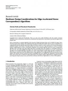
2.2 Functional diagram The SIM548C have two circuits parts (GSM part and GPS part) which are place on one PCB and have only one connector .The following figure shows a functional diagram of the SIM548C and illustrates the mainly functional part: GSM part: z The GSM baseband engine z Flash and SRAM z The GSM radio frequency part z The antenna interface z The board-to-board interface GPS part: z The SIRFIII GPS engine z The GPS radio frequency part z The antenna interface z The board-to-board interface
www.agelectronica.com SIM548C_HD_V1.01
17
www.agelectronica.com 09.05.2008
www.agelectronica.com
www.agelectronica.com
SIM548C Hardware Design
Figure 1: Functional diagram
2.3 Evaluation board In order to help you on the application of SIM548C, SIMCom can supply an Evaluation Board (EVB) that interfaces the SIM548C directly with appropriate power supply, SIM card holder, RS232 serial port, handset port, earphone port, antenna and all GPIOs of the SIM548C. For details please refer to the SIM548C-EVB_UGD document.
www.agelectronica.com SIM548C_HD_V1.01
18
www.agelectronica.com 09.05.2008
www.agelectronica.com
www.agelectronica.com
SIM548C Hardware Design
3 GSM application interface All hardware interfaces except RF interface that connects SIM548C to the customers’ cellular application platform is through a 60-pin 1.27mm pitch board-to-board connector. Sub-interfaces included in this board-to-board connector are described in detail in following chapters: z
Power supply and charging control
z
GSM serial interface
z
Two analog audio interfaces
z
SIM interface
Electrical and mechanical characteristics of the board-to-board connector are specified in Chapter 6. There are also ordering information for mating connectors.
3.1 Pin description Table 5: Board-to-Board connector pin description Power Supply PIN NAME
I/O
VBAT
VRTC
VCHG
www.agelectronica.com SIM548C_HD_V1.01
I/O
I
DESCRIPTION
DC CHARACTERISTICS
4 VBAT pins of the board-to-board connector are dedicated to connect the supply voltage. The power supply of the GSM part of 548C has to be a single voltage source of VBAT= 3.4V...4.5V. It must be able to provide sufficient current in a transmitting burst which typically rises to 2A.mostly. These 4 pins are voltage input
Vmax= 4.5V Vmin=3.4V Vnorm=4.0V
RTC current input from the backup battery when the VBAT is not supplied for the system. Current output to backup battery when the main battery is present and the backup battery is low voltage state.
Vmax=2.0V Vmin=1.2V Vnorm=1.8V Iout(max)= 20uA
Voltage input for the charge circuit; making the system detect the charger.
Vmax=5.25V Vmin=1.1 * VBAT Vnorm=5.1V
19
Iin=5 uA
www.agelectronica.com 09.05.2008
www.agelectronica.com
www.agelectronica.com
SIM548C Hardware Design
GND
Digital ground
Power on or power off PIN NAME
I/O
DESCRIPTION
DC CHARACTERISTICS
PWRKEY
I
Voltage input for PWRKEY. PWRKEY should be pull low to power on or power off the system. The user should keep pressing the key for a moment when power on or power off the system. because the system need margin time in order to assert the software.
VILmax=0.2*VBAT VIHmin=0.6*VBAT VImax=VBAT
PIN NAME
I/O
DESCRIPTION
DC CHARACTERISTICS
MIC1P MIC1N
I
Positive and negative voice-band input
Audio DC Characteristics refer to chapter 3.9.4
MIC2P MIC2N
I
Auxiliary positive voice-band input
SPK1P SPK1N
O
Positive and negative voice-band output
SPK2P SPK2N
O
Auxiliary positive voice-band output
BUZZER
O
Buzzer output
Audio interface
AGND
and
and
negative
negative
Analog ground
Display interface DISP_DATA
I/O
DISP_CLK
O
DISP_D/C
O
DISP_CS
O
DISP_RST
O
LCD display interface
VILmin=0V VILmax=0.9V VIHmin=2.0V VIHmax= 3.2V VOLmin=GND VOLmax=0.2V VOHmin=2.7V VOHmax=2.9V
GERNERAL PURPOSE input/output PIN NAME
I/O
DESCRIPTION
DC CHARACTERISTICS
NETLIGHT
O
Network status indication
STATUS
O
Another indication for system on/off
GPIO0
I/O
General purpose input/output port
GPIO1
I/O
General purpose input/output port
VILmin=0V VILmax=0.9V VIHmin=2.0V VIHmax= 3.2V VOLmin=GND VOLmax=0.2V VOHmin=2.7V VOHmax=2.9V
www.agelectronica.com SIM548C_HD_V1.01
20
www.agelectronica.com 09.05.2008
www.agelectronica.com
www.agelectronica.com
SIM548C Hardware Design
Serial port PIN NAME
I/O
DESCRIPTION
DC CHARACTERISTICS
DTR
I
Data terminal ready
VILmin=0V
RXD
I
Receive data
VILmax=0.9V
TXD
O
Transmit data
VIHmin=2.0V
RTS
I
Request to send
VIHmax= 3.2V
CTS
O
Clear to send
RI
O
Ring indicator
DCD
O
Data carrier detection
DBG_TXD
O
Serial interface for debugging only
DBG_RXD
I
VOLmin=GND VOLmax=0.2V VOHmin=2.7V VOHmax=2.9V
Debug port
SIM interface PIN NAME
I/O
DESCRIPTION
DC CHARACTERISTICS
SIM_VDD
O
Voltage supply for SIM card
The voltage can be select by software automatically either 1.8V or 3V
SIM_DATA
I/O
SIM data output
SIM_CLK
O
SIM clock
SIM_PRESENCE
I
SIM card detection
SIM_RST
O
SIM reset
VILmin=0V VILmax=0.3* SIM_VDD VIHmin=0.7* SIM_VDD VIHmax= SIM_VDD +0.3 VOLmin=GND VOLmax=0.2V VOHmin= SIM_VDD -0.2 VOHmax= SIM_VDD
PIN NAME
I/O
DESCRIPTION
DC CHARACTERISTICS
ADC0
I
General purpose analog to digital
Input voltage range: 0V to
converter.
2.4V
For measure the battery temperature
0-1.2V
AUXADC
TEMP_BAT
I
3.2 Operating modes The table below briefly summarizes the various operating modes referred to in the following chapters.
www.agelectronica.com SIM548C_HD_V1.01
21
www.agelectronica.com 09.05.2008
www.agelectronica.com
www.agelectronica.com
SIM548C Hardware Design
Table 6: Overview of operating modes Mode
Function
Normal operation
GSM/GPRS
Module will automatically go into SLEEP mode if DTR is set
SLEEP
to high level and there is no on air hardware interrupt (such as GPIO interrupt or data on serial port). In this case, the current consumption of module will reduce to the minimal level. During SLEEP mode, the module can still receive paging message and SMS from the system normally.
GSM IDLE
Software is active. Module has registered to the GSM network, and the module is ready to send and receive.
GSM TALK
Connection is going on between two subscribers. In this case, the power consumption depends on network settings such as DTX off/on, FR/EFR/HR, hopping sequences, antenna.
GPRS
Module is ready for GPRS data transfer, but no data is
STANDBY
currently sent or received. In this case, power consumption depends on network settings and GPRS configuration.
GPRS DATA
There is GPRS data in transfer (PPP or TCP or UDP). In this case, power consumption is related with network settings (e.g. power control level), uplink / downlink data rates and GPRS configuration (e.g. used multi-slot settings).
POWER DOWN
Normal shutdown by sending the “AT+CPOWD” command or using the PWRKEY. The power management ASIC disconnects the power supply from the base band part of the module, and only the power supply for the RTC is remained. Software is not active. The serial port is not accessible. Operating voltage (connected to VBAT) remains applied.
Minimum
Use the “AT+CFUN” command can set the module to a minimum functionality
functionality
mode without remove the power supply. In this case, the RF part of the module
mode (without
will not work and the SIM card will not be accessible,or both RF part and SIM
remove power
card will be closed all, and the serial port is still accessible. The power
supply)
consumption in this case is very low.
Alarm mode
RTC alert function launches this restricted operation while the module is in POWER DOWN mode. The module will not be registered to GSM network and
www.agelectronica.com SIM548C_HD_V1.01
22
www.agelectronica.com 09.05.2008
www.agelectronica.com
www.agelectronica.com
SIM548C Hardware Design
only parts of AT commands can be available. GHOST Mode
GHOST mode means off and charging mode. In this mode, the module can not
(Charge-only
be registered to GSM network and only limited AT commands can be
mode)
accessible, the following way will launch GHOST mode: z
From POWER DOWN mode: Connect charger to the module’s VCHG pin, and battery is present while the module is power down.
z
From Normal mode: Connect charger to the module’s VCHG pin, and battery is present, then power down the module by “AT+CPOWD=1”
Charge mode
Start charging while the module is in normal mode (including: SLEEP, IDLE,
during normal
TALK, GPRS IDLE and GPRS DATA)
operation
3.3 Power supply The power supply of SIM548C GSM part is from a single voltage source of VBAT= 3.4V...4.5V. In some case, the ripple in a transmitting burst may cause voltage drops when current consumption rise to typical peaks of 2A.So the power supply must be able to provide sufficient current up to 2A.
For the VBAT input, a local bypass capacitor is recommended. A capacitor (about 100µF, low ESR) is recommended. Multi-layer ceramic chip (MLCC) capacitors can provide the best combination of low ESR and small size but may not be cost effective. A lower cost choice may be a 100 µF tantalum capacitor (low ESR) with a small (0.1 µF to 1µF) ceramic in parallel, which is illustrated as following figure. The capacitors should put as close as possible to the module VBAT pins.
Figure 2: Reference circuit of the VBAT input
www.agelectronica.com SIM548C_HD_V1.01
23
www.agelectronica.com 09.05.2008
www.agelectronica.com
www.agelectronica.com
SIM548C Hardware Design
The circuit design of the power supply depends strongly on the power source where this power is drained. The following figure is the reference design of +5V input source power supply. The designed output for the power supply is 4V, thus a linear regulator can be used. If there’s a big difference between the input source and the desired output (VBAT), a switching converter power supply will be preferable because of its better efficiency especially with the 2A peak current in burst mode of the module. The single 3.6V Li-Ion cell battery type can be connected to the power supply of the module VBAT directly. But the Ni_Cd or Ni_MH battery types must be used carefully, since their maximum voltage can rise over the absolute maximum voltage for the module and damage it.
Figure 3: Reference circuit of the source power supply input The following figure is the VBAT voltage ripple wave at the maximum power transmit phase, the test condition is VBAT=4.0V, VBAT maximum output current =2A, CA=100µF tantalum capacitor (ESR=0.7Ω) and CB=1µF.
Figure 4: VBAT voltage drop during transmit burst
www.agelectronica.com SIM548C_HD_V1.01
24
www.agelectronica.com 09.05.2008