Hardware, Software and Mechanical Cosimulation for Automotive Applications P. Le Marrec, C.A. Valderrama, F. Hessel, A.A. Jerraya TIMA Laboratory 46 Avenue Felix Viallet 38031 Grenoble France fPhilippe.Lemarrec, CA.Valderrama, Fabiano.Hessel,
[email protected] M. Attia, O. Cayrol PSA Peugeot Citroen, DRAS route de gizy 78943 Velizy-Villacoublay France
Abstract The design of automotive systems requires the joint design of hardware, software and micro-mechanical components. In traditional design approaches the different parts are designed by separate groups and the integration of the overall system is made at the final stage. This scheme may induce extra delays and costs because of interfacing problems. This paper presents a new automotive system design approach that offers many advantages including efficient design flow and shorter time to market. The key idea of our approach is to allow for early validation of the overall system through co-simulation. The design starts with a high level specification of each part. In our approach software is described in C, hardware is described in VHDL and mechanical parts are described in MATLAB. A C-VHDLMATLAB co-simulation is then used for functional validation of the initial specification. During the design process, the hardware and software parts may be refined using specific techniques and tools. The refinement steps are also validated through co-simulation. In this approach we use two kind of co-simulations: untimed co-simulation is used for functional validation and timed co-simulation for realtime validation. This paper describe the design approach and its successful application to an example from an automotive industry.
1. Introduction The use of electronics within cars is becoming more and more important. It is expected that the electronic parts will constitute more that 20% of the price of future cars [8]. The joint design control of various mechanical parts with elec-
tronic parts and specially micro-controllers is a very important area for automotive design. In traditional design approaches the different parts are designed by separate groups and the integration of the overall system is made at the final stage. This scheme may induce extra delays and costs because of interfacing problems. The necessity for a more efficient design approaches allowing for joint design of different parts is evident. Co-simulation constitutes an important step towards this direction. It gives the designer the ability to validate the whole system’s behavior before the implementation of any of its parts. This paper presents a new automotive system design approach that offers many advantages including efficient design flow and shorter time to market. The key idea of our approach is to allow for early validation of the overall system through co-simulation. We developed a unified co-simulation environment which permits the simultaneous design of systems consisting of mechanical parts controlled by digital circuits and software. This environment allows for both timed and untimed co-simulations. The design starts with a high level specification of each part. In our approach software is described in C, hardware is described in VHDL and mechanical parts are described in MATLAB. A C-VHDL-MATLAB co-simulation is then used for functional validation of the initial specification. During the design process, the hardware and software parts may be refined using specific techniques and tools. The refinement steps are also validated through co-simulation. In this approach we use two kind of co-simulations: untimed cosimulation is used for functional validation and timed cosimulation for real-time validation. For the timed simulation we use a hardware microprocessor model for the software part. The approach allow for modular design where each part of the system may be designed by a separate group expert in its field. It allows for the validation of the over-
slaves. The master simulator is in charge of fixing the time slots where other simulators should run. The main advantage of this model is its simplicity of implementation. However it implies lots of restrictions on the organization of the systems. The most general coordination scheme is the asynchronous model. In this case the simulators exchange data stamped with time [1]. In this case slow simulators need to queue their data in order to respect timing. The drawback of this model is the complexity of the implementation. Such a system would require a complex coherence management strategy in order to avoid deadlocks. Another popular synchronization scheme is the lock-step model. This scheme makes use of a global real time server that provide a global time frames to synchronize the different simulators. With this scheme each simulator decomposes its computation into steps according to a local time. It is allowed to proceed to the next step only if the local time is smaller that the global time. This model is applicable under some conditions only. In some cases it may produce quite efficient results this will be detailed later. The implementation of cosimulation may follow one of two schemes: composition or concurrent execution of simulators. In the composition approach, the different models are compiled into a common languages (e.g. C or executable code) and then linked with some simulation kernel [6]. In this case co-simulation is made by the execution of the linked object. Depending on the target language used, this model may produce a very efficient results. But this approach makes hard the separate debug of the different modules. In fact the only access to the intermediate data during simulation is provided by the simulation kernel. This is generally restricted to the intermodule communication. For instance it makes it difficult to modify some internal parameters of the modules during co-simulation. This may be very useful in automotive applications. The concurrent execution of simulators scheme overcome all these drawback. In this model each module is simulated using a specific simulator. The different simulators communicate through a co-simulation bus. The only drawback of this model is the overhead induced by the cosimulation bus. The applicability of this model depends on the ration (Computation time/communication time). This ratio is very high for applications including analog components (e.g. Electromechanical components) that requires very large computation steps for small interval time (e.g. ns). In the case of automotive applications this ration is quite low because the time intervals are generally high. For instance in our case we use the discrete simulation mode of MATLAB in order to lower this ratio. The approach described in this paper is based on a co-simulation environment called VCI [11]. VCI allows to run concurrently several simulators using a co-simulation bus. VCI allows for both untimed and timed co-simulation. For timed cosimulation several synchronization schemes are possible.
all system using co-simulation. Additionally the approach allows for the refinement and the correct design of the interfaces between the different parts of the system before the design of a real prototype. This new approach was applied successfully for automotive design. This paper is organized as follows: Section 2 is dedicated to the general features of the co-simulation environment. In section 3, the co-simulation scheme is detailed. An illustrative industrial example is presented in section 4 and finally some performance issues are discussed in section 5.
2. Co-simulation approaches Co-simulation is an emerging technology for heterogeneous system design it allows for multi-language design and validation [7]. Although the multi-language approaches are used since long time in the area of system modeling and simulation [2], its to the design step is quite recent. This started with hardware software co-simulation ([4], [5], [9], [3]) and now it is being extended to all kind of other heterogeneous systems. In this section we will limit our interest to co-simulation models used in automotive also called mechatronics [8]. In this case the co-simulation involves generally three kind of components: hardware, software and mechanical. When different languages are used for the specification of different parts, the validation step require co-simulation techniques. There mainly two kind of co-simulations: timed and untimed simulation. Timed co-simulation, also called real time co-simulation, considers both functionality and timing aspects while untimed cosimulation, also called functional co-simulation considers only the functional aspects of a specification. The major difficulty in timed cosimulation is the synchronization between the software , the hardware and the mechanical parts. In the functional cosimulation the exchange of data between simulator is controlled by events. In this case only the order of operations is checked. The timing aspects are ignored. This model of cosimulation schedules and verifies the behavior of the system, and establishes the coherence of the interconnection between the sub-systems, showing a global flashover [7] of the system functionality. In timed co-simulation [6] the data is exchanged within specific time frames. For instance, when a data is not consumed in a specific timing interval it may be lost. This kind of cosimulation implies that simulators associates a time frame to each operation. Since co-simulation implies the concurrent execution of several simulators that may have different execution speed and timing models, a synchronization scheme is needed. The synchronization is needed in order to coordinate the concurrent execution of simulators. There are several synchronization scheme. The simplest one is the master slave model. With this scheme [4] a specific simulator plays the role of the master while all the other proceed as 2
3. The Automotive design approach Figure 1 shows the methodology used to produce and to validate the initial specification for an automotive system including hardware, software and mechanical parts. The design starts with an analysis of the system requirements and a high level definition of the various functions of the system. The partitioning of the system is made manually. Then, the modeling of the mechanical system is made using MATLAB. The hardware is modeled using VHDL and the software is modeled using C. Co-simulation is performed in order to validate this initial executable model. The different parts may be refined using specific methods. During this design process co-simulation may be used to validate the different parts at different abstraction levels. This strategy allows to fully use the competence of different groups in the same design flow.
Figure 2. : Software modelization should note that in our case the timed co-simulation is reduced to a VHDL MATLB co-simulation. The co-simulation makes use of the MATLAB and the VHDL debuggers. The VHDL debugger transparently runs the Graphical User Interface, and adds some specific commands to the micro-controller GUI. It allows the user to placard the assembler trace, the registers, the I/O properties of the processor, and commands to modify the memory, the registers, and other for control in globe the microprocessor. With this model, we can display the entire behavior of the micro-controller as if it was implemented with the compiled software. The overall hardware software model is cycle accurate. For the MATLAB side, we fix the time step as equal to a clock cycle in the hardware side. This time step is quite small to allow for an acceptable accuracy on the mechanical side. The overall cosimulation configuration is shown in Figure 3. The interaction with the VHDL simulation is made through CLI [10] and the interaction with MATLAB is made using the ”Engine package” of MATLAB. The overall co-simulation environment is automatically generated by VCI starting from a configuration file that gives the details of the interconnect between different modules and the synchronization scheme.
Figure 1. : design methodology Starting from the initial C-VHDL-MATLAB specification the design process includes mainly two validation steps before the implementation may proceed. The first cosimulation is aimed at functional validation and follows the untimed scheme. The second step is aimed at real time verification and makes use of timed co-simulation. In order to allow for timed simulation of software (C programs) we use a cycle accurate model of the target micro-controller in order to emulate the execution of the software at the clock cycle level. In this case, the accuracy of the co-simulation is the clock cycle. The micro-controller model may be a C program or a VHDL description. In our case we use the Siemens C167 micro-controller. For real timed simulation of the software we use a VHDL model of the C167. This is provided by Siemens and includes both a microprocessor entity and a memory entity which is associated with the C software part compiled by a C167 compiler. Organization of the overall VHDL model is shown in Figure 1. One
Figure 3. : Co-simulation configuration
4. Industrial application This section describes the use of the automotive design approach described above for the design of two applications at PSA (Peugeot Citroen, Velizy - Paris). The first one is the control of the parasitic variation of the acceleration pedal 3
5. Results The application of the untimed co-simulation was quite straightforward. In both applications this step allowed to validate the overall behavior of the system including the interactions between the different parts. As expected we had more difficulties with the timed co-simulation. Although we succeeded to co-simulate both applications using the timed approach, the co-simulation time was quite slow. In fact in our case the speed of co-simulation was imposed by the VHDL model of the C167. The model we had was able to run only few instruction per second which implies unacceptable time for realistic simulation. In fact the simulation of one millisecond of real time requires about 10 minutes of VHDL simulation with the C167 on a SPARC station. Of course the co-simulation speed may be boosted using a faster model of the processor. It is expected that a C model of the processor will be able to execute about 1 million instruction per second. This would induce a drastic reduction in the timed co-simulation time.
Figure 4. : Global view of the pedal regulation application
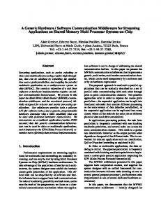
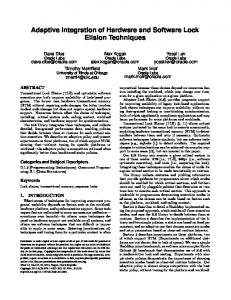
movement in the electric car ( 4) and the second is the regulation of the car hydraulics suspension. These both systems contained a MATLAB behavioral model of the vehicle and a software control module aimed to be executed on the C167 micro-controller. In the example of Figure 4, the system regulates a pedal watchword with the speed of a electrical motor. The software application eliminates the parasitic vibration of the user pedal control, and the motor behavior vibration to have the best regulation between the pedal pressure and the speed of the motor. Figure 5 shows the timed co-simulation of the first example. The screen shows both VHDL debugger executing the hardware , the C167 model executing the software and the MATLAB/SIMULINK environment simulating the mechanical parts.
Figure 5. : Timed simulation of the pedal regulation application
4
6. Conclusion
[11] C. Valderrama, A. Changuel, P. Raghavan, M. Abid, T. Ismail, and A. Jerraya. A unified model for co-simulation and co-synthesis of mixed hardware/software systems. The European Design and Test Conference ED&TC95 Paris, France, March 1995.
This paper presented a new automotive system design approach that offers many advantages including efficient design flow and shorter time to market. The key idea of our approach is to allow for early validation of the overall system through co-simulation. The design starts with a high level specification of each part. In our approach software is described in C, hardware is described in VHDL and mechanical parts are described in MATLAB. A C-VHDLMATLAB co-simulation is then used for the validation of the initial specification. The approach allows for timed and untimed co-simulation allowing to validate both functional and timing properties of the system under design
References [1] W. Chang, S. Ha, and E. Lee. Heterogeneous simulation mixing discrete event models with dataflow. Invited Paper, Journal on VLSI Signal Processing, Vol. 13, No. 1, January 1997. [2] W. Chang, A. Kalavade, and E. Lee. Effective heterogeneous design and cosimulation. Chapter in Hardware/Software Co-design, G.DeMicheli and M.Sami, eds., NATO ASI Series Vol. 310, Kluwer Academic Publishers, 1996. Also presented at NATO Advanced Study Institute Workshop on Hardware/Software Codesign, Lake Como, Italy, June 1830, 1995. [3] M. Gasteier and M. Glesner. Bus-based communication synthesis on system-level. Proceedings of the 9th International Symposium on System Synthesis (ISSS ’96), IEEE Computer Society Press, page p. 65, 1996. [4] K. Hagen and H. Meyr. Timed and untimed hardwaresoftware co-simulation: Application and efficient implementation. International Workshop on Hardware-Software Codesign, Cambridge, October 1993. [5] S. Lee and J. Rabaey. A hardware-software cosimulation environment. International Workshop on Hardware-Software Codesign, Cambridge, October 1993. [6] W. Loucks, B. Doray, and D. Agnew. Experiences in real time hardware-software cosimulation. Proc VHDL Int. Users Forum (VIUF), Ottawa, Canada,, pages P. 47–57, April 1993. [7] N. C. Petrellis, A. N. Birbas, M. K. Birbas, E. P. Mariatos, and G. D. Papadopoulos. Simulating hardware, software and electromechanical parts using communicating simulators. Seventh IEEE International Workshop on Rapid System Prototyping, pages p 78–82, june 1996. [8] A. Rault, Y. Bezard, A. Coustre, and T. Halconruy. Systems integration in the car industry. PSA, Peugeot-Citroen, 2 route de gizy, 78140 Velizy Villacoublay. France, 1996. [9] J. Rowson. Hardware/software co-simulation. Proceedings of the 31st Design Automation Conference, San Diego, CA, USA, pages p. 439–440, June 1994. [10] Synopsys. VHDL System Simulator Interfaces Manual:CLanguage Interface, June 1993.
5