uses a small hardware co-processor to optimize the performance. This is the first step towards exploring all possibilities for hardware/software co-designed ...
Hardware/Software Co-design for Hyperelliptic Curve Cryptography (HECC) on the 8051 µP Lejla Batina2 , David Hwang1 , Alireza Hodjat1 , Bart Preneel2 , and Ingrid Verbauwhede1,2 1
University of California, El. Engineering Dept., Los Angeles, CA 90095 Katholieke Universiteit Leuven, ESAT/COSIC, Kasteelpark Arenberg 10, B-3001 Leuven-Heverlee, Belgium {Lejla.Batina, Bart.Preneel, Ingrid.Verbauwhede}@esat.kuleuven.ac.be {dhwang, ahodjat, ingrid}@ee.ucla.edu 2
Abstract. Implementing public-key cryptography on platforms with limited resources, such as microprocessors, is a challenging task. Hardware/software co-design is often the only answer to implement the computationally intensive operations with limited memory and power at an acceptable speed. This contribution describes such a solution for Hyperelliptic Curve Cryptography (HECC). The proposed hardware/software co-design of the HECC system was implemented and co-simulated using the GEZEL design environment [3]. As a low-cost platform, we chose an 8-bit 8051 microprocessor to which one small hardware co-processor was added for field multiplication. We show that the Jacobian scalar multiplication can be computed in 2.488 sec at 12 MHz on this platform if a minimal hardware module is added i.e. a hardware multiply-add unit. This optimal solution provides a factor of 26 speed-up over a softwareonly solution. Keywords: HECC, GF(2m ), genus 2 curves, hardware/software codesign, embedded implementation.
1
Introduction
Public-key cryptosystems are present in almost all spheres of digital communication e.g. for financial, governmental and medical applications; they form an essential building block for network security protocols (e.g. SSL/TLS, IPsec, SSH). The best-known and most commonly used public-key cryptosystems are based on factoring (RSA) and on the discrete logarithm problem in GF(p) (DiffieHellman, ElGamal, Schnorr, DSA) [18]. They allow secure communications over insecure channels without prior exchange of a secret key and they also enable digital signatures. Elliptic Curve Cryptography (ECC), which was proposed in the mid 1980s by Miller [20] and Koblitz [14], is based on a different algebraic structure. ECC offers shorter certificates, lower power consumption and better performance on some platforms. Besides that, ECC offers more “security per bit” as no sub-exponential algorithm is known that solves the discrete logarithm J.R. Rao and B. Sunar (Eds.): CHES 2005, LNCS 3659, pp. 106–118, 2005. c International Association for Cryptologic Research 2005 �
Hardware/Software Co-design for HECC on the 8051 µP
107
problem in this group. However, only in the past few years has ECC started replacing some of the RSA applications. In 1988 Koblitz suggested to use the generalization of Elliptic Curves (EC) for cryptography, the so-called Hyperelliptic Curves (HEC) [15]. While ECC applications are highly developed in practice, the use of HEC is still of pure academic interest. However, one advantage of HECC resides on the fact that the operand size for HECC is at least a factor of two smaller than the one of ECC. More precisely, while typical bit-lengths for ECC are at least 160 bits, for HECC this lower bound is around 80 bits (in the case of genus 2 curves). This fact makes HECC a very good choice for platforms with limited resources. Almost all existing HECC implementations consider binary fields and curves of genus two or three; this choice is motivated by security reasons [9]. Software implementations were developed on general purpose processors and on embedded microprocessors e.g. on an ARM [21,26] and some research has been performed on a hardware implementation. However, this article describes the first HECC implementation using a hardware/software co-design. More precisely, we have implemented the HECC divisor multiplication on the 8051 microprocessor, which uses a small hardware co-processor to optimize the performance. This is the first step towards exploring all possibilities for hardware/software co-designed HECC implementations. Such an investigation is of special interest as embedded devices are believed to be of vital importance for a broad area of pervasive computing such as sensor networks and wireless applications. First we examined the pure software i.e. C/assembly implementations. Next some small extra hardware was added, which facilitates the field operations, in particular the inversion and multiplication in the binary field. We conclude that even with very limited hardware resources one can obtain an attractive performance. We used formulae of Byramjee and Duquesne [8] to achieve optimized divisor doubling operation. For the optimal hardware/software co-design we used GEZEL as a design environment. GEZEL is especially suitable for the exploration of domain-specific coprocessor and multiprocessor micro architectures as it can provide cycle-true hardware/software co-simulation with various embedded core instruction set simulators. The remainder of this paper is organized as follows. Section 2 lists some relevant previous work in HECC on embedded platforms. In Sect. 3 some background information on HECC is given. Details of our implementation are specified in Sect. 4 and results are listed in Sect. 5. Some directions for future work and conclusions are given in Sect. 6.
2
Previous Work
Algorithms for HECC and implementations have been studied intensively in the past years. A significant amount of work has been performed on investigating the formulae for the group operation [17,24,22,8]. Explicit formulae for genus 2 curves are given by Lange [17] for arbitrary fields and for various types of coordinates. There exist practical results for both software platforms (general purpose or
108
L. Batina et al.
embedded processor) [26,21] and hardware devices, such as FPGAs [7,13]. The most detailed and complete reference dealing with software as well as hardware implementations is [24]. For embedded processors, a large amount of work has been performed for the ARM platform [26,23,4,21]. Pelzl et al. [21] have implemented the group operation of genus 2 and 3 for HECC on an ARM7 processor. They compared the results with ECC implementation (with corresponding security) and showed that HECC performance is comparable to the one of ECC. The performance for divisor scalar multiplication on the ARM microprocessor for genus 2 was further optimized in [23] and compared to genuses 3 and 4. They proved that genus 3 is the fastest, requiring less than 70 ms on an ARM7 running at 80 MHz. The work of Wollinger et al. [26] considered not just the ARM7TDMI but also the ColdFire and a PowerPC. In addition, they provided the first thorough comparison of ECC and HECC on those platforms. The first complete hardware implementation of HECC was given by Boston et al. [7]. Wollinger et al. [25] investigated HECC implementation on a VLSI coprocessor. They used projective coordinates and completed their research on VLSI platforms started in [6,5]. They compared co-processors using affine and projective coordinates and concluded that the latter should be preferred for hardware implementations. They used a curve of a special form (y 2 + xy = x5 + f1 x + f0 ), which allowed for more optimized formulae. In [13] three different architectures on a FPGA have been examined for vast area of applications. With respect to the platform, we mention here other relevant experiences with curve-based cryptography. Woodbury et al. [27] showed that EC point multiplication can be performed on an 8051 microcontroller in less than 2 sec as a pure software solution. However, they used a 134-bit OEF at lower security level. Gura et al. [10] compared ECC and RSA on 8-bit CPUs and proved that Public-key Cryptography is viable on small devices. For hardware/software co-design the only relevant work that we are aware of is the one of Kumar and Paar [16]. They implemented ECC on an 8-bit AVR microcontroller with some extra hardware for field multiplications. They show that a 163-bit point multiplication can be calculated in 0.113 sec with a microcontroller running at 4 MHz. We can compare this to our solution as both implementations are for similar platforms and the fields offer the same level of security.
3
Hyperelliptic Curve Cryptography (HECC)
We now present the mathematical background for hyperelliptic curves including the algorithms for efficient arithmetic in the Jacobian group. More details on the theory of hyperelliptic curves can be found in [19]. 3.1
Hyperelliptic Curves
Let GF(2m ) be an algebraic closure of the field GF(2m ). Here we consider a hyperelliptic curve C of genus g = 2 over GF(2m ), which is given with an equation of the form:
Hardware/Software Co-design for HECC on the 8051 µP
C : y 2 + h(x)y = f (x)
in
GF(2m )[x, y],
109
(1)
where h(x) ∈ GF(2 )[x] is polynomial of degree at most g (deg(h) ≤ g) and f (x) is a monic polynomial of degree 2g + 1 (deg(f ) = 2g + 1). Also, there are no solutions (x, y) ∈ GF (2m ) × GF (2m ) which simultaneously satisfy the equation (1) and the equations: 2v + h(u) = 0, h� (u)v − f � (u) = 0. These points are called singular points. For the genus 2, in the general case the following equation is used y 2 + (h2 x2 + h1 x + h0 )y = x5 + f4 x4 + f3 x3 + f2 x2 + f1 x + f0 . For our implementation we used the so-called type II curves [8], which are defined with h2 = 0, h1 �= 1. In particular, the authors recommended to use curves of the form: y 2 + xy = x5 + f3 x3 + x2 + f0 , since they combine a simpler arithmetic with a good security level. A�divisor D is a formal sum of points on the hyperelliptic curve C i.e. � D = mP P and its degree is degD = mP . Let Div denotes the group of all divisors on C and Div0 the subgroup of Div of all divisors with degree zero. The Jacobian J of the curve C is defined as quotient group J = Div0 /P . Here P is the set of all principal divisors, where a divisor D is called principal if D = div(f ), � for some element f of the function field of C (div(f ) = P ∈C ordP (f )P ). The discrete logarithm problem in the Jacobian is the basis of security for HECC. In practice, the Mumford representation according to which each divisor is represented as a pair of polynomials [u, v] is usually used. Here, u is monic of degree 2, degv < degu and u|f − hv − v 2 (so-called reduced divisors). For implementations of HECC, we need to implement the multiplication of elements of the Jacobian i.e. divisors with some scalar. m
3.2
Algorithms for HECC
Divisor Multiplication. The divisor scalar multiplication is achieved by use of divisor addition and doubling. We used the NAF algorithm to reduce the number of additions. Divisor Addition and Doubling. Let the quintuple [U1 , U0 , V1 , V0 , Z] stand for [x2 + u1 x + u0 , v1 x + v0 ] = [x2 + UZ1 x + UZ0 , VZ1 x + VZ0 ]. This form allows us to complete both point operations without inversion. Only one inversion and four multiplication are required at the end to convert back from projective to affine coordinates. We used the formulae from [8] for doubling and we used the same approach to get formulae for addition in the case of mixed coordinates. The addition for type II curve has the same complexity as the one of Lange [17] i.e. it takes 44M , but doubling has been further optimized to 31M (here M denotes number of multiplications/squaring). The formulae for the addition are given in Table 1. The numbers in parenthesis correspond to the case of mixed addition. Finite Field Arithmetic. We used the polynomial basis representation with the irreducible polynomial being pentanomial in GF(283 ). Each element of the field can be represented as an 11-byte word. The field addition of two vectors in hardware or software in GF(2m ) is simply the xoring of the two vectors. The field
110
L. Batina et al. Table 1. Formulae used for the divisor addition Step Calculations 1 Precomputation and resultant r: �21 = Z1 · U21 , U �20 = Z1 · U20 , Z = Z1 · Z2 , U � � V21 = Z1 · V21 , V20 = Z1 · V20 , �21 , t2 = U10 · Z2 + U �20 , t1 = U11 · Z2 + U 2 t0 = U11 · t1 + t2 · Z1 , r = t0 · t2 + t1 · U10 2 Compute almost inverse: t1 = inv1 , t3 = inv0 3 Compute almost s: t4 = V10 · Z2 + V�20 , t5 = V11 · Z2 + V�21 , w2 = t0 · t4 , w3 = t1 · t5 ; s1 = (t0 + Z1 · t1 ) · (t4 + t5 ) + w2 + w3 · (Z1 + U11 ); s0 = w2 + U10 · w3 4 Precomputations: � = R · s3 ; R = Z · r, s0 = s0 · Z, s3 = s1 · Z, R � �� � · S; � S3 = s3 2 , S = s0 · s1 , S� = s3 · s1 , S� = s0 · s3 , R =R
# mult. 12M (6M )
5
Compute l: �21 , l0 = S · U �20 , l1 = (S� + S) · (U �21 + U �20 ) l2 = S� · U �� +l2 + l0 , l2 = l2 + S;
3M
6
Compute U’: �21 ) + t2 · S� + R · [t1 · r + s1 · Z]; U0 � = s0 2 + s1 2 · t1 · (t1 + U � 2 U1 = S� · t1 + R , l2 = l2 + U1 � , t4 = U0 � · l2 + S3 · l0 , t5 = U1 � · l2 + S3 · (U0 � + l1 ); � · S3 , U1 � = R � · U1 � , U0 � = R � · U0 � ; Z� = R Compute V’: �� � V0 � = t4 + R · V20 ; �� � � V1 = t5 + R · (V21 + Z);
17M
7
total
8M (7M )
9M
2M
51M (44M )
multiplication is the most costly operation in our system, since it is performed thousands of times during the course of a single divisor multiplication. While the inversion algorithm is actually more complex, it is only performed a single time (for the case of projective coordinates) and hence it is not the bottleneck in our initial implementation. We discuss our choices for field multiplication in more detail in Sect. 4.
4 4.1
Implementation 8051 Microprocessor
Here we give a brief overview of the 8051 microprocessor platform. An 8051 is an 8-bit microcontroller originally designed by Intel that consists of several components: a controller and instruction decoder, an ALU, 128 bytes of internal
Hardware/Software Co-design for HECC on the 8051 µP
111
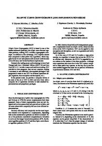
memory (IRAM), up to 64K of external RAM (XRAM) addressed by a 16bit DPTR register, and up to 64KB of external program memory or 4KB of internal program memory (ROM). The 8051 also has 128 bytes of special function registers (SFRs), which are used to store system values such as timers, serial port controls, input/output registers, etc. The architecture is shown in Figure 1, which is based on the Dalton 8051 core from UC Riverside [2]. 8051 CORE
Decoder
Controller
Program ROM
Internal ALU
RAM/SFRs I/O ports P0−P3
External RAM
Co−Processor
Fig. 1. The architecture of the 8051 microprocessor
An external RAM module (XRAM) can be attached to the 8051 core when the 128 bytes of internal RAM are insufficient, which is often the case in publickey cryptosystems. The 8051 interfaces to the outside world via a serial port as well as four input/output register ports, labeled P0 through P3. It also should be noted that the 8051 in its original form relies on a clock division principle. That is, the external clock entering into the device is actually divided by 12 to produce the system clock. Thus, a 12-MHz external clock would produce an 8051 with a 1-MHz machine clock cycle, with most instructions requiring 1 or 2 machine cycles. Newer 8051 cores attempt to reduce the clock division [1]. The clock division principle can serve as an advantage to codesigned systems in that the coprocessor circuitry can inherently operate at 12x the internal 8051 machine rate. 4.2
Various Implementation Options
The paper presents two types of HECC implementations on the 8051 processor. The first type is a pure software implementation - either a pure C model operating on the 8051 or a mixed C/assembly model in which most of the functions are performed in C while the GF(283 ) finite field multiplier is performed in assembly. The second type is a mixed hardware/software model in which some of the functions are performed in C while the GF(283 ) finite field operations (multiplication/addition/inversion) are performed in hardware. The hardware operators
112
L. Batina et al.
and the 8051 are connected by a memory-mapped interface, over the 8051’s P0, P1, and P2 I/O port interfaces. Software C/ASM Implementation. The first implementation is a pure C implementation, compiled onto the 8051 processor using the Keil suite. This implementation uses a single function in C to combine the multiplication and reduction functions. As a first improvement the multiplication routine is replaced by an assembly code. Multiplication: In the software implementation, we used a modified form of Algorithm 4 of [11] to implement fast software multiplication. The algorithm is a fast comb-based multiplication method with windows implemented for a 32-bit processor with window size of 4. Based upon initial simulation results, for an 8-bit processor, we found that a window size of 2 provides faster performance. Reduction: To reduce the multiplication result by the irreducible polynomial, a fast reduction technique was used. This technique was based on Algorithm 6 of [11]. We have used a similar approach but modified the algorithm to implement reduction using our GF(283 ) pentanomial and a word-size of 8 bits. Inversion: The inversion function for this case is implemented as the Extended Euclidean Algorithm. Hardware/Software Implementation. The second type of HECC implementation is a hardware/software co-design i.e. software routines were enhanced with binary field operations in hardware. In the first attempt we implemented a data path which includes a hardware GF(283 ) multiplier. Figure 2 shows this data path. The data IO ports from the 8051 processor are 8-bits long and the multiplication is performed on the GF(283 ) operands. There is an instruction register that controls the HW data path from the 8051 processor. The supported instructions for the data path of Figure 2 are as shown in Table 2: Table 2. Instructions for the data path Instruction Definition LOADA Load 8-bits of data from the 8051 to Register A of HW data path LOADB Load 8-bits of data from the 8051 to Register B of HW data path DOMULT Perform GF(283 ) mult. on A and B and put the results in C GETC Return 8-bits of data from Register C of HW data path to the 8051
Due to the fact that the data is transferred back and forth from the CPU to the HW multiplier there is a lot of I/O overhead. In order to optimize the total performance we tried to reduce the I/O transfers with minimum additional memory storage added to the data path. The key observation is that in the schedule of divisor’s double and add operations (see Table 1) there are many expressions of the following form: k1 = f3 · t0 + t1 .
Hardware/Software Co-design for HECC on the 8051 µP
113
Initially for such expression, f3 and t0 were moved to the hardware multiplier, the multiplication was performed in the hardware, then the result was returned back to the CPU and the addition with t1 was performed in the SW. In order to speed up this expression the hardware multiplier was replaced with a GF(283 ) “multiply-and-add” data path. For this purpose a hardware adder and a feedback line that can keep the result of the multiplication in hardware was added to the original data path and therefore, the number of I/O transfers decreased with not much of extra hardware. For the new datapath (Figure 3), the instructions shown in Table 3 were added. Table 3. The new instructions for the data path Instruction Definition MOVE_CTOB Move the data in Register C to Register B DOADD Perform GF(283 ) addition on A and B and put the results in C
Moreover, in the software routines that implement the divisor’s double and add operations, we moved the coprocessor’s instructions up and down in the schedules of the divisor’s operations, so that we do not have to repeatedly load the same values into the internal register A of the data path. The performance gain of these optimizations will be provided in the next section. In addition, for the best performance in the final HW/SW implementation of HECC on the 8051 processor, the GF(283 ) inversion operation was performed in HW. The same HW datapath is used to implement the inversion algorithm which consists of repeated multiplications. The details of the hardware GF(283 ) multiplication and inversion are given after introducing our design environment. Design Environment: At this stage we briefly introduce the design environment GEZEL [3] in which we model the co-designed system. In our application, we used the Dalton 8051 ISS to perform cycle-accurate simulations for our software only (C and C/ASM) implementation. For the hardware/software system, we designed our co-processor multiplier using GEZEL’s hardware description language. The language syntax is primarily used to describe the FSMD (finite state machine plus datapath) system model. Thus, a datapath for the co-processor was designed and its corresponding control logic was also designed in the GEZEL language. After the design of the hardware co-processor, we attached the co-processor to the input/output ports of the 8051 ISS (P0-P3) using the GEZEL design environment, and then performed timing and functional verification. GEZEL gave us the ability to co-simulate the 8051 with clock division circuitry as it interfaced with a 12 MHz hardware module in a cycle-exact manner. Upon verification of the functionality of the multiplier co-processor, the GEZEL code was automatically converted to RTL VHDL and input into Synplicity for FPGA synthesis. Multiplier: In the first version of the multiplier, the multiplier implements a finite field multiplication and simultaneously a corresponding reduction in a
114
L. Batina et al. b 84
c
8
Mult
84
8 dout
84
din a
ins
8
Fig. 2. Data path for the initial design
b 84
Mult
84 c
8
84
8
din
dout
a
Add
ins
84
8
Fig. 3. Data path of the new co-processor
bit-serial implementation. A bit-serial implementation was chosen for area compactness as well as to take advantage of the 12x increase in effective clock rate of the co-processor over the 8051 core. In the second version, the multiplier was enhanced with the additional “multiply-and-add” instruction and datapath element, as described previously. Inversion: Inversion in binary fields can be replaced by a chain of multiplications (and squarings). It is of interest if squarings are faster than multiplication such as for normal bases. First by means of Fermat’s little theorem we have: a−1 = m m−1 −1 2 ) , for all a ∈ GF(2m ). The technique to compute this in a2 −2 = (a2 optimal way is the basis for the idea of Itoh and Tsujii [12]. Their method is especially suited for normal basis but can be applied on polynomial basis as well. Here we consider the case for m odd, so m − 1 is even. Then we can write: m−1
m−1
m−1
m−1
m−1
−1 a2 = a(2 2 −1)(2 2 +1) = (a2 2 −1 )2 2 a2 2 −1 . In our case for GF(283 ) 83 82 41 41 41 we get: a−1 = a2 −2 = (a2 −1 )2 = ((a2 −1 )2 a2 −1 )2 , which means that we m−1 m−1 −1 −1 need to use formula for a2 , but now m − 1 is odd. In this case: a2 = m−1 m−2 2 −2 2 −1 2 = a(a ) . aa By repeated use of these formulae we can compute the inverse by only 90M . The total number of multiplications (or squarings) required to compute an inverse in GF(2m ) is given with: �log2 (m − 1)� + w(m − 1) − 1. Here w(k) denotes the Hamming weight of some positive integer k. m−1
Hardware/Software Co-design for HECC on the 8051 µP
5
115
Results
Here we give detailed results on all three platforms and we discuss them further. In Table 4 the timings for all finite field operations are given for hardware and software. Timings for all basic operations are shown and in the last row, the “multiply-and-add” operation is also added. One can notice that inversion in software takes a very long time because it is implemented using the Extended Euclidean Algorithm. The software implementation of inversion by means of Fermat would be already much faster, but we decided to move this operation in hardware anyway. Namely, we concluded that although our software implementations could possibly be further optimized, it would still be difficult to achieve an efficient HECC implementation. Another observation is that the numbers for addition and multiplication in hardware are the same. The reason for that is because the majority of the time for multiplication and addition on hardware is spent on the IO transfers. Therefore, the time to perform single multiplication (83 cycles) or an addition (1 cycle) is not more than even one 8-bit IO transfer from 8051 to the accelerator. Moreover, this time (2.3 ms) is also very close to the time it takes to do ab + c (2.5 ms), and this is for the same reason as well. However, the fact that this operation is used repeatedly allowed for a speed-up in the new datapath. Sizes of XRAM and ROM are given in bytes (B). Table 4. Implementation results for operations in GF(283 ) for hardware and software routines Operation Perf. [� Cl. Cyc.] Perf. [ms]@12MHz XRAM [B] ROM [B] Addition (SW) 38 K 3.2 54 608 Multiplication (SW) 650 K 54.1 122 2065 Inversion (SW) 467.2 M 38.9 K 160 2383 Addition (HW) 28.2 K 2.3 53 934 Multiplication (HW) 28.2 K 2.3 53 934 Inversion (HW) 788.5 K 65.7 75 1835 ab + c (HW) 30.5 K 2.5 44 942
The results for the scalar multiplication of divisor for various implementation options are given in Table 5. FPGA area is given in number of LUTs without XRAM and ROM which are specified separately. As can be seen in Table 5, a significant increase in performance is provided by moving the finite-field multiplication from C to assembly, as shown in the first two rows. An additional improvement is made when the multiplication is moved into hardware; however at this point the timing does not improve dramatically because at this point the inversion algorithm (rather than the finite-field multiplication) is the critical path element of the system. Moving the inversion into hardware rapidly reduces the timing (from 52 to 4.1518 seconds). An additional 40% timing reduction occurs after the point operation signal flow graphs are analyzed and manipulated,
116
L. Batina et al.
Table 5. Implementation results for divisor multiplication in GF(283 ) for all three platforms FPGA XRAM ROM Perf.[s] Implementation [� LUTs] [Bytes] [Bytes] @12MHz C (Inversion in SW) 3300 820 11754 191.7 C+ASM(Inversion in SW) 3300 820 12284 64.9 C+HW multiplier 3600 820 11754 52 (Fig. 2-Inversion in SW) C+HW multiplier 3600 927 12789 4.1518 (Fig. 2-Inversion in HW) C+HW multiplier 3781 936 11524 2.4880 (Fig. 3-Inversion in HW)
and the new “multiply-and-add” operation is created and used. From this table it can also be seen that the number of LUTs does not change whether inversion is performed in hardware or software. This is due to the fact that even if inversion is done in software, the same accelerator is used for field multiplication. Now we compare our performance results with other work on embedded processors. Table 6 shows that our result features a practical HECC implementation in constrained environments. First, it should be mentioned that it is extremely difficult to compare the performance of cryptographic primitives on different embedded processors, since each processor presents a unique architecture and memory structure. The discussion below is primarily to reference prior art. The first two references relate to the ARM7, which is a 32-bit platform and features completely different architecture than the 8051. Even so, the second reference is of the same order as ours using frequency scaling for rough normalization. The most suitable comparison to this work is [16] and [10]. Gura et al. achieve the shown performance using a “faster” 8051, i.e. an 8051 whose clock division was much less than 12x. They also demonstrate the well-known fact that the AVR is much faster than the 8051 (though exactly how much faster is subject to debate). This provides perspective when comparing to the ECC implementation of Kumar and Paar [16]. Table 6. Implementation results for divisor multiplication on various embedded platforms Reference [23] [4] [16] [10] this work
PKC HECC HECC ECC ECC HECC
Field Platform Frequency [MHz] Performance [ms] GF(283 ) ARM7 80 71.56 GF(280 ) ARM7 80 374 GF(2163 ) AVR 4 113 GF(2160 ) 8051 12 4580 GF(283 ) 8051 12 2488
Hardware/Software Co-design for HECC on the 8051 µP
6
117
Conclusions and Future Work
This paper shows that even on a small 8-bit processor one can implement hyperelliptic curve cryptography efficiently. We have designed a small hardware module that results in a significant speed-up compared with a software-only solution. We believe that hardware/software co-design offers a new alternative for low-power and low-footprint devices. We plan to explore other trade-offs between hardware and software in order to find the best partition. Additional options can be made available by exploiting parallelism between HECC operations.
References 1. Dallas semiconductor ds89c420 ultra-high-speed microcontroller. http://www. maxim-ic.com/quick view2.cfm/qv pk/2963. 2. Dalton 8051 processor. http://www.cs.ucr.edu/∼ dalton/8051/. 3. GEZEL design environment. http://www.ee.ucla.edu/∼ schaum/gezel. 4. S. Baktır, J. Pelzl, T. Wollinger, B. Sunar, and C. Paar. Optimal tower fields for hyperelliptic curve cryptosystems. In Proceedings of 38th Asilomar Conference on Signals, Systems and Computers, Pacific Grove, USA, November 7-10 2004. 5. G. Bertoni, L. Breveglieri, T. Wollinger, and C. Paar. Finding optimum parallel coprocessor design for genus 2 hyperelliptic curve cryptosystems. In Proceedings of ITCC, April 5-7, 2004, Las Vegas, Nevada, USA, 2004. 6. G. Bertoni, L. Breveglieri, T. Wollinger, and C. Paar. Hyperelliptic Curve Cryptosystem: What is the Best Parallel Hardware Architecture?, chapter in Embedded Cryptographic Hardware: Design and Security. Nova Science, 2004. 7. N. Boston, T. Clancy, Y. Liow, and J. Webster. Genus two hyperelliptic curve coprocessor. In B. S. Kaliski Jr., C ¸ . K. Ko¸c, and C. Paar, editors, Proceedings of 4th International Workshop on Cryptographic Hardware and Embedded Systems (CHES), number 2523 in Lecture Notes in Computer Science, pages 400–414. Springer-Verlag, 2002. 8. B. Byramjee and S. Duquesne. Classification of genus 2 curves over F2n and optimization of their arithmetic. Cryptology ePrint Archive: Report 2004/107. 9. P. Gaudry. An algorithm for solving the discrete log problem on hyperelliptic curves. In B. Preneel, editor, Advances in Cryptology: Proceedings of EUROCRYPT 2000, volume 1807 of LNCS, pages 19–34, 2000. 10. N. Gura, A. Patel, A. Wander, H. Eberle, and S. C. Shantz. Comparing Elliptic Curve Cryptography and RSA on 8-bit CPUs. In M. Joye and J. J. Quisquater, editors, Proceedings of 6th International Workshop on Cryptographic Hardware and Embedded Systems (CHES), Lecture Notes in Computer Science 3156, pages 119– 132, 2004. 11. D. Hankerson, J. L. Hernandez, and A. Menezes. Software implementation of elliptic curve cryptography over binary fields. In C ¸ . K. Ko¸c and C. Paar, editors, Proceedings of 2nd International Workshop on Cryptographic Hardware and Embedded Systems (CHES), number 1965 in Lecture Notes in Computer Science, pages 1–24. Springer-Verlag, 2000. 12. T. Itoh and S. Tsujii. Effective recursive algorithm for computing multiplicative inverses in GF(2m ). Electronics Letters, 24(6):334–335, 1988.
118
L. Batina et al.
13. H. Kim, T. Wollinger, Y. Choi, K. Chung, and C. Paar. Hyperelliptic curve coprocessors on a FPGA. In Workshop on Information Security Applications - WISA, Jeju Island, Korea, August 23-25 2004. 14. N. Koblitz. Elliptic curve cryptosystem. Math. Comp., 48:203–209, 1987. 15. N. Koblitz. A family of Jacobians suitable for Discrete Log Cryptosystems. In S. Goldwasser, editor, Advances in Cryptology: Proceedings of CRYPTO’88, number 403 in Lecture Notes in Computer Science, pages 94–99. Springer-Verlag, 1988. 16. S. Kumar and C. Paar. Reconfigurable instruction set extension for enabling ECC on an 8-bit processor. In Proceedings of International Conference on FieldProgrammable Logic and Applications (FPL) 2004, Antwerp, Belgium, August 30September 1, 2004. 17. T. Lange. Formulae for arithmetic on genus 2 hyperelliptic curves. Applicable Algebra in Engineering, Communication and Computing, 15(5):295–328, February 2005. 18. A. Menezes, P. van Oorschot, and S. Vanstone. Handbook of Applied Cryptography. CRC Press, 1997. 19. A. Menezes, Y.-H. Wu, and R. Zuccherato. An elementary introduction to hyperelliptic curves, chapter Appendix, pages 155–178. Springer-Verlag, 1998. N. Koblitz: Algebraic Aspects of Cryptography. 20. V. Miller. Uses of elliptic curves in cryptography. In H. C. Williams, editor, Advances in Cryptology: Proceedings of CRYPTO’85, number 218 in Lecture Notes in Computer Science, pages 417–426. Springer-Verlag, 1985. 21. J. Pelzl, T. Wollinger, J. Guajardo, and C. Paar. Hyperelliptic curve cryptosystems: Closing the performance gap to elliptic curves. In C. Walter, C ¸ . K. Ko¸c, and C. Paar, editors, Proceedings of 5th International Workshop on Cryptograpic Hardware and Embedded Systems (CHES), number 2779 in Lecture Notes in Computer Science, pages 351–365. Springer-Verlag, 2003. 22. J. Pelzl, T. Wollinger, and C. Paar. High performance arithmetic for hyperelliptic curve cryptosystems of genus two. In Proceedings of ITCC, April 5-7, 2004, Las Vegas, Nevada, USA, 2004. 23. J. Pelzl, T. Wollinger, and C. Paar. Special Hyperelliptic Curve Cryptosystems of Genus Two: Efficient Arithmetic and Fast Implementation, chapter in Embedded Cryptographic Hardware: Design and Security. Nova Science Publishers, 2004. 24. T. Wollinger. Software and Hardware Implementation of Hyperelliptic Curve Cryptosystems. PhD thesis, Ruhr-University Bochum, Germany, 2004. 25. T. Wollinger, G. Bertoni, L. Breveglieri, and Christof Paar. Performance of HECC coprocessors using inversionfree formulae. International Workshop on Information Security & Hiding, Singapore (ISH ’05). 26. T. Wollinger, J. Pelzl, V. Wittelsberger, C. Paar, G. Saldamli, and C ¸ . Ko¸c. Elliptic and hyperelliptic curves on embedded µP. ACM Transactions on Embedded Computing Systems, 3(3):509–533, 2004. 27. A. D. Woodbury, D. V. Bailey, and C. Paar. Elliptic curve cryptography on smartcards without coprocessors. In Proceedings of Fourth Smart Card Research and Advanced Applications (CARDIS 2000) Conference, 2000.