Hardware Speech Recognition for User Interfaces in Low Cost, Low Power Devices Sergiu Nedevschi
[email protected]
Rabin K. Patra
[email protected]
Eric A. Brewer
[email protected]
Department of Electrical Engineering and Computer Science University of California at Berkeley
ABSTRACT
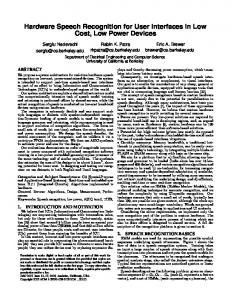
plays and thereby decreasing power consumption, which translates into lower battery costs. We propose a system architecture for real-time hardware speech Consequently, we investigate hardware-based speech interrecognition on low-cost, power-constrained devices. The system is intended to support real-time speech-based user interfaces faces as an alternative, or complement, to visual interfaces. as part of an effort to bring Information and Communication Our goal is to enable the manufacture of very cheap, general or application-specific devices, equipped with language tools that Technologies (ICTs) to underdeveloped regions of the world. are vital in overcoming language and literacy barriers [22]. Our system architecture exploits a shared infrastructure model. The concept of speech recognizers based on custom hardware The computationally intensive task of speech model training and retraining is performed offline by shared servers, while the is not new, mainly due to the potential for parallelization in actual recognition of speech is conducted on low-cost hand-held speech decoding. Although many architectures have been proposed throughout the years [7], the impact of these approaches devices using custom hardware. The recognizer is extremely flexible and can support mul- has been limited. However, we believe that custom hardware tiple languages or dialects with speaker-independent recogni- speech recognition is worth revisiting for several reasons: tion.Dynamic loading of speech models is used for changing • Focus on power: Very low-power solutions are required for language grammar and retraining, while reprogramming is used successful hand-held use in developing regions, and, as argued to support evolution of recognition algorithms. The focus on by many, such as Broderson [6], custom hardware can be 100 small sets of words (at one time) reduces the complexity, cost times more power-efficient than software-based solutions. and power consumption. We design the speech decoder, the • Potential for high volume (given low cost): As opposed central component of the recognizer, and we validate it via a to the past, today’s abundance of embedded devices could make prototype FPGA implementation. We then use ASIC synthesis the use of speech-based interfaces ubiquitous. • On-chip memory: Memory bandwidth, a traditional botto estimate power and size for the design. Our evaluations demonstrate an order of magnitude improve- tleneck in parallelizing speech computation, can be easily overment in power compared with optimized recognition software come using today’s technology, by integrating multiple blocks of running on a low-power embedded general-purpose processor of FLASH or SRAM memory along with logic on the same chip. We aim for a platform that is: a) flexible, allowing any lanthe same technology and of similar capabilities. The synthesis also estimates the area of the design to be about 2.5mm2 , show- guage and grammar to be loaded (India alone has over 16 laning potential for lower cost. In designing and testing our recog- guages and 400 dialects), and various recognition algorithms and techniques to be used; b) re-trainable, for increasing recogninizer we use datasets in both English and Tamil languages. tion accuracy and speaker-dependent adaptation; c) scalable, Categories and Subject Descriptors: C.3 [Special-Purpose permitting accuracy to be increased by utilizing more resources, and Application-Based Systems]: Real-time and embedded sys- but without modifying the underlying design; and d) efficient, tems; B.7.1 [Integrated Circuits]: Algorithms implemented in enabling real-time or near real-time recognition. Our solution relies on HMMs (Hidden Markov Models), the hardware. preferred modeling technique for accurate recognition, and we General Terms: Algorithms, Design, Measurement, Perforreduce the complexity by using UI-specific recognition. Our mance. technique ensures that only a small set of words, typically less Keywords: Speech recognition, low power, ASIC, tamil, TIER. than 100, are possible in a given context, although the whole application may use a much larger vocabulary. Words are grouped 1. INTRODUCTION AND MOTIVATION into active sets corresponding to applications and UI contexts. We believe that ICTs (Information and Communication TechConsidering the above requirements, we implement only the nologies) are empowering technologies with tremendous value, core recognition part of the problem in custom hardware. The but only for those with access to them. Unfortunately, statis- more computationally intensive process of training which can tics [23] show that around 3 billion people have an annual pur- also be done offline is delegated to shared servers. A full dechasing power of less than US$2000, and that 862 million adults scription of the recognition platform is given in section 8. are illiterate; for these people, costs and current user interfaces (UIs) prevent them from enjoying the benefits of ICT. 2. SPEECH RECOGNITION BASICS In this context, low-cost and low-power speech interfaces can HMM models are used for representing the possible symbol play an essential role in overcoming the above-mentioned barri- sequences underlying speech utterances. Figure 1 shows the ers [22]: they can provide ICT access to illiterate or semi-literate flow of data in a speech recognition system. Training takes people; they can reduce device cost by replacing expensive dis- as input a large number of speech utterances along with their transcriptions into phonemes and outputs the speech models for Permission to make digital or hard copies of all or part of this work for the phonemes. The utterances to be recognized first undergo a personal or classroom use is granted without fee provided that copies are spectral analysis stage, also called the feature extraction stage. not made or distributed for profit or commercial advantage and that copies Typical feature representations are smoothed spectra or linear bear this notice and the full citation on the first page. To copy otherwise, to prediction coefficients. republish, to post on servers or to redistribute to lists, requires prior specific Speech decoding solves the following problem: given an obserpermission and/or a fee. vation sequence O = O1 , O2 . . . On (each Oi represents a feature DAC 2005, June 13–17, 2005, Anaheim, California, USA. vector), and a set of HMMs, (each representing a phoneme), the Copyright 2005 ACM 1-59593-058-2/05/0006 ...$5.00.
Transcription
Training and Retraining
Speech Models
Spectral Analysis & Data Preparation
Raw Speech
Recognition iy
d
en d
Word network
Grammar Parsing
decoder tries to find the model (M ) that best matches the observation sequence, such that the probability of the observation sequence, P (O|M ), given the model M is maximized. An N-state Markov model is defined by a set of N states forming a finite state machine such that aij is the transition probability from state i to j. Each state is additionally associated with a probability density function bj (Ot ) representing the probability that a particular observation Ot is emitted by state j for observation number t. These probabilities are estimated during training. The observation probability distributions are represented by Gaussian Mixture Densities. The probability P (O|M ) is approximated by the probability of the state sequence Q maximizing P (O, Q|M ). This can be easily estimated using the Viterbi decoding algorithm. For a given model M, let ψj (t) represent the maximum likelihood of having observed the sequence O, and being in state j at time t. This partial likelihood can be computed efficiently using the following recursion: i
p
ax
close
Figure 1: Generic Speech Recognition System
ψj (t) = max{ψi (t − 1)aij }bj (Ot ),
ow
open
Feature vectors
Word lexicon n
Speech Recording
(1)
The maximum likelihood Pm (O|M ) is then given by: ψN (n) = maxi {ψi (n)aiN }. As repeated multiplications of small values lead to underflow, log probabilities are used. This formulation casts the problem as a dynamic programming problem where we want to find the path with the maximum likelihood. The spoken utterances modeled by HMMs are sub-word constructions called phonemes, while words are chains of phonemes. The word models are then aggregated using a language model.
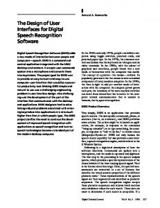
2.1 Design Decisions Taking into account the system requirements, the following design decisions were made. • Use regular grammars language models and unified recognition network: Although preferred for large vocabularies, n-gram language models imply an exponential search space. Hence, we use regular grammar based language models. This simplifies the search and improves accuracy. Given a regular grammar description of the language, we construct a network of words similar to a finite state automaton. Words are then expanded into chains of phonemes, and each phoneme in its turn is expanded into an HMM. Finally, we obtain a large unified HMM, the recognition network. We then perform Viterbi computation on this recognition network to determine the most likely path through the network. Figure 2.1 shows an example word network and its expansion. • Use token-passing algorithm for probability computation: Although the Viterbi algorithm computes the probability of the most likely path through the recognition network of states, it does not actually retain the path itself. However, unlike isolated word recognition where the sequence of sub-word states is uninteresting, we need the actual matching words. The token-passing algorithm [25] makes the sequence of words explicit. With token passing, computations for each iteration are very similar at every state, and can be performed in parallel.
n
one window
two three
Figure 2: Example Recognition Network. The word ”open” is a chain of the component phonemes: ”ow”, ”p”, ”ax” and ”n”. Each of the phoneme is expanded into a chain of HMM states. The language for the network is: (((open|close)window(one|two|three))|)∗.
3. HARDWARE DECODER ARCHITECTURE 3.1 Design Decisions • Parallel design: The computations in the recognition network are symmetric and inherently parallelizable, with few data dependencies. By using parallelism, we can greatly reduce the clock frequency required for real-time recognition, and apply voltage scaling [1] to reduce power. We therefore choose to employ a set of very simple processing elements (PEs) operating in parallel. We also ensure that the PE design is simple enough for the size of the chip to remain small. • Use on-chip embedded FLASH and SRAM memories: Recent technological improvements enable the integration of several manufacturing processes on the same chip. Systemon-chip solutions show orders of magnitude improvement over traditional designs in terms of both cost and power [6], because the packaging cost of individual components is avoided, the wires are shorter and operating voltages are lower. Since little data sharing happens between processing elements, perprocessor local on-chip memory is desirable. This also reduces the power consumption and memory access latencies. The HMM model parameters used for observation probability calculations are tied to a particular language and are modified very rarely (only for a new language or new models) although they can be large in size. Thus low-power FLASH memories with high densities can be used. However most of the recognition network state is dynamic and changes during the course of an UI application. Since the size of memory required for dynamic state is smaller, fast SRAMs are the best choice. • Use of scaled fixed-point arithmetic: We use a software implementation of the speech decoder to compare the recognition accuracy of performing floating-point computation versus scaled fixed-point computation. We performed tests to determine the data width and scaling required for each arithmetic operation (section 6.4). • Single-cycle datapath and use of gated clocks: Since our design runs at low frequencies (5MHz), we can afford to have long critical paths and gated clocks. Thus we choose a singlecycle architecture for each PE, and we employ gated clocks to reduce power dissipation.
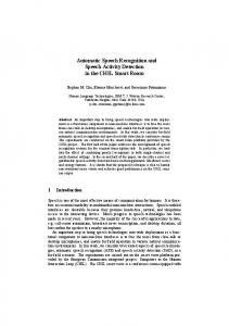
3.2 Architecture Description Figure 3 illustrates our parallel architecture, featuring a set of simple processing elements (PEs) connected through a communication bus. The PEs have their own local FLASH and SRAM memories. Flash blocks are used to store phoneme acoustic parameters, while SRAMs store dynamic data. These acoustic parameters are initially loaded by the device microcontroller via the bus. Every PE can access the local memories of any other PE using the bus. Thus, we construct a very simple NUMA (non-uniform memory access) shared-memory multiprocessor. In order to minimize communication and to simplify synchronization, we use one of the PEs as a coordinator. Each regular processing element executes its chunk of work and goes to sleep. The coordinator reads data from the local memories of other
Coordinator PE 1
Local Memory System
Bus Interface
Processor
24
16
PE 2 PE N Bus Adapter
General Purpose CPU
BUS INTERFACE UNIT
Spectral Analyzer
Speech Decoder
16 24-bit registers
16
16
24
A L U
4.
LOG EXP
FLASH
20
SRAM Memory Other system components
bitration, giving local operations priority, which enables fixedlatency local operations. In order to avoid starvation of remote accesses, the local processor is prevented from issuing new memory accesses until the remote operation completes.
INSTR FLASH
Figure 3: System Architec- Figure 4: Processing ture Element PEs, aggregates it, writes the results to the local memories of the PEs that need it, and wakes up the PEs, which resume computation.
3.3 Processing Elements Figure 4 shows the hardware structure of a PE. Datapath Design: The datapath is in the RISC-style, with a 24-bit wide data path and 16 24-bit general-purpose registers. The memory is word-addressable with 16-bit words, and consists of a FLASH memory block (up to 64KB) and a smaller SRAM block (up to 16KB). The design has several functional units: an ALU, a logarithm and an exponentiation unit. The functional units share a common result bus, and we implement a very simple result bus reservation mechanism using a result shift register, since instructions have fixed latencies. This allows the functional units to operate in parallel; instruction issue stalls during a bus conflict. The multiplication operation is implemented using an array multiplier. The log/exp functional units use a method that computes one high-radix digit of the result at a time [11]. Local memory operations take two cycles to complete, but several memory accesses can be pipelined. The inter-PE communication and synchronization operations are supported by remote load/store instructions, which execute the operations over the bus, on the local memory of a specified PE. Instructions: The instruction set has 25 16-bit instructions: arithmetic and logic operations, memory-access instructions (local and remote loads and stores) and control instructions. Memory Operations: Although the choice of a wider datapath (24 bits) than the memory word (16 bits) might seem odd, we do this to minimize the memory size and bandwidth required, while ensuring reasonable precision for the scaled fixedpoint arithmetic operations. This implies that two memory operations might be needed for some loads and stores, but such operations are infrequent. Power: As the processor runs at very low frequencies for lower power consumption, we can afford long critical paths. Consequently, most of the instructions are single-cycle, except for memory access (local and remote), log and exp operations. Low frequencies also allow the use of gated clocks, which enable the PEs to go into SLEEP mode when idle.
3.4 Inter-Processor Communication Over the Bus PEs are connected through a dedicated communication bus. It is a semi-synchronous bus with 24 data/address multiplexed lines. Transactions take a variable number of cycles, and an acknowledgment is required to signal transaction completion. The bus is multi-master and uses daisy-chain arbitration. Memories are not dual-ported; simultaneous local and overthe bus accesses to the same memory block are handled by ar-
WORKLOAD SCHEDULING
The parallel architecture is flexible to support various possible workload division among PEs. An efficient workload scheduling implies optimizing for locality and balanced execution time. The decoder’s computation is iterative, and each iteration processes a new observation vector from the speech front-end. In every iteration, each state in the recognition network executes two steps: 1) it computes the observation probability for the current observation and 2) it examines all the incoming tokens and selects the best one (maximum likelihood). After valuating several computation scheduling schemes, we present the chosen alternatives.
4.1 Proposed Scheduling Scheme Observation probability computation: The observation probability computation involves evaluating Gaussian mixtures for each state of the recognition network. However, we observe that all the words in the network use the same pool of phonemes. Thus, in the first phase of scheduling, we divide the pool of phonemes equally among the PEs. For each observation, every PE computes probabilities for its own share of phonemes. The results are then collected at the coordinator and distributed to all the PEs in the second phase. As a result, the total amount of computation is proportional to the number of phonemes used rather than the size of the whole recognition network. Since the set of phonemes is fixed for a language, this workload scheduling must be performed only at language load time. The acoustic model parameters required for observation probability computation are loaded in the local FLASH of each PE through the communication bus. Since new language models are loaded quite infrequently, the latency for loading the FLASH is tolerable, and the number of writes to FLASH is small. Token Probability Scheduling: In the second step of an iteration, each state of the recognition network collects tokens from all the incoming edges and selects the one with maximum likelihood. Thus it is desirable to assign adjacent states to the same PE, as inter-state communication is faster through local memory. Therefore, the token computation for all of the states belonging to the same word are assigned to the same PE. Tokens exchanges between states belonging to different words is always done through the coordinator. Words are assigned to PEs every time a different application is loaded, since applications have relatively smalls vocabularies. In practice, this assignment implies writing the SRAM of every PE. The delay imposed by this operation is acceptable, since it is done only at application load time. However, grammar structure (links between words in the network) and information about the active set of words changes with the current UI context. These changes are low-delay operations since the information in stored in the SRAMs. To summarize, the scheduling is performed as follows: 1) For observation probability computations, phonemes are assigned to PEs at language load time. 2) For computing token probabilities, whole words are assigned to PEs at application load time. 3) Word interconnections and information about active word sets are changed for every new UI context.
5.
IMPLEMENTATION
In order to evaluate our proposed hardware decoder design and the various tradeoffs, we first developed a software version of the decoder that implements the exact same algorithms as the proposed design. This software decoder is based on the Hidden Markov Model Toolkit (HTK) [20]. It has a modular architecture such that different functions can be performed either in software or in a hardware design simulator. We implement the decoder in the Verilog hardware descrip-
tion language, and perform RTL simulations in Modelsim [14] to verify that the results match the software implementation. FPGA Implementation: To validate the correctness of our design, we deploy it on a FPGA array board, composed of 20 Xilinx Virtex-E XCV2000E FPGA chips. Loading the memory contents at synthesis time, we confirm that results are identical with our software implementation and Modelsim simulations. ASIC Implementation: To estimate our design’s area and energy savings, we synthesize our design in an 0.18 micron CMOS process at a core voltage of 1.08V using the Synopsys Design Compiler. Because of the difficulty in accessing technology libraries for embedded FLASH and SRAM memory blocks, we take the following approach: we eliminate the memory blocks from our design and treat them as external components. We then measure the area and energy consumption of the resulting chip; we separately estimate power dissipation and area for the memory blocks, and finally add the numbers, also taking into consideration the overhead incurred by placement and routing of the circuit.
6.
EVALUATION
6.1 Experimental Setup We consider a UI application that recognizes numbers in English. The database for this application is a set of 6000 speech utterances in English. We use the American English lexicon consisting of 28 phonemes. The word network had 30 different words (spelling out numbers and digits). The phoneme model is based on linear HMMs with 3 emitting states. We perform the training using the tools provided by HTK. After considering the tradeoffs presented in section 6.4, we choose to implement a version of our decoder consisting of 8 processing elements, capable of performing real-time speech recognition using 8 Gaussian mixtures for observation probability computation. In order to support a vocabulary of up to 40 words we require 8 FLASH modules of 10KB each, as well as 8 SRAM modules of 2KB each.
6.2 Area Estimation We separately estimate the area of the logic part of the decoder and the memory modules. Synthesizing the logic part of decoder for 8 processing elements in 0.18µm technology, we obtain an area of approximately 1.216mm2 . Table 1 presents the breakdown of this area.
6.3 Energy Savings We estimate the power dissipation of our custom hardware decoder design, and we compare it to the alternate method of performing speech recognition on a software version of the decoder running on a general purpose processor, namely a lowpower ARM running at 206MHz. The recognition accuracy for both the cases is almost identical as we use the same decoding algorithms, with insignificant differences related to the fixed-point computation precision. In order to compare energy efficiency, we evaluate the total energy consumption in recognizing the same speech utterance (1.2s long), using different numbers of Gaussian mixtures, for which recognition yields different levels of accuracy. Since energy consumption improvements often come at the cost of performance, we confirm that it is not the case by computing the energy-delay product as well. Power Estimate for Proposed Decoder: Using Synopsys synthesis tools and Modelsim simulations, we determine the average power dissipation for the logic part of the decoder to be 5.125mW in the 0.18 µm process at 1.08V. This power can be broken up into a leakage power of 0.108mW and dynamic power of 5.017mW, excluding the power consumed in the memory blocks. For estimating the power dissipation in the FLASH memories and SRAM we use published parameters for off-chip 0.18 micron FLASH [3] and SRAM [15] memory cells. Running Modelsim simulations, we compute the memory bandwidth for different types of blocks. Table 3 presents the parameters, the memory bandwidth and the total power for the different types of the memories. The total dissipation of the decoder is 19.70mW. Param
Volt 1.8V
Read Cur 4mA
Write Cur NA
Inst FLASH Data FLASH SRAM Power
1.8V
4mA
NA
1.8V NA
20mA NA
20mA NA
Access Time 70ns, (40ns) 70ns, (40ns) 70ns NA
BW (Macc/s) 40.8
Power (mW) 11.75
1.6
0.81
0.8 43.2
2.016 14.57
Table 3: Power consumption in memory
Power Estimate for 0.18 µm ARM: We estimate the power consumed by a low-power ARM processor of the same process (0.18µm) but running optimized HTK speech decoding software. We choose the processor and the clock rate such that it Component % area Component Size Area yields the same recognition throughput as our hardware decoder (KB) (mm2 ) ALU 35.9% running at 5MHz. Register files 38.9% FLASH 80 0.93 Although instruction wise power estimates are available for Shift Units 10.14% SRAM 16 0.42 the Intel SA-1100 processor (0.35 µm at 1.65-2.0V) in JouleTagger Unit 3.27% Decoder Logic 1.216 Track [2], it is difficult to get accurate estimates for the newer Control Unit 0.51% 0.18µm Intel processors (PXA 26x/27x series). Total (8 PEs) 2.566 To overcome this problem, we scale the power estimates of the SA-1100 processor to 0.18µm technology using two differTable 1: Decoder Logic Table 2: Area Breakdown ent methods. Although this scaling methodology will not give We then estimate FLASH and SRAM memory area. FLASH den-us very accurate power estimates, we believe that this is a reasities have increased drastically, varying from 1MB/mm2 for the sonable approximation given that our aim is to show more than slower NAND FLASH memories, to 128KB/mm2 for random- an order of magnitude improvement. access NOR FLASH memories [13]. We use the more conserWe use SimpleScalar [24] to get instruction profiles and cycle vative estimate, obtaining an area of 0.625 mm2 for all eight counts for the program running on the ARM processor. We use blocks. Since blocks are small, we add 50% overhead for addi- the instruction profile and the per instruction power estimates tional addressing and decoding logic, obtaining a total area of from JouleTrack to get to the total energy for the speech utterance considered. The instruction counts and CPI estimates from 0.93 mm2 . Similarly, we assess the total area of the SRAM blocks to be SimpleScalar are used to estimate the energy-delay product. Method 1: Use the typical power estimates provided by Intel 0.42 mm2 . We again rely on conservative figures by assuming a density of 300Kbit/mm2 , although current technologies can for the SA-1100 [9] at 1.75V and the PXA 26x series [8] at 1.0V. The ratio of the typical power estimates at 200 MHz is achieve more than 735Kbit/mm2 . Thus, as shown in Figure 2, the total area of our decoder is 400mW/178mW = 2.24. We use this as the scaling factor. Method 2: We determine the power dissipation for the 0.18µm estimated at 2.566 mm2 . This implies that it could be manufactured at low cost and could easily be integrated as an additional technology by using well-accepted CMOS scaling techniques. We first use the data given in [2] to break down the power module in a system-on-chip device.
1
15 20 25 30 Word inaccuracy(%)
10 1 0.1
15 20 25 Word inccuracy(%)
30
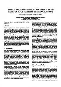
Figure 5: Energy and Energy-delay product comparison: 0.18µm ARM and our decoder. consumption of an instruction into dynamic and static (leakage) components. We then use the model proposed in [10] where the total power of a circuit can be expressed as Ptot = Pdyn + 2 Pstat = CL Vcc f + Vcc Ntrans kdesign Ileak . We then use figures from [10] and the publicly available ITRS roadmaps [17] to scale the dynamic and static power of each instruction to 0.18µm. Conclusion: The results of the comparisons are presented in Figure 5. Our design has an energy improvement factor ranging from 10 to 12.75 over the software solution on the 206MHz, for various accuracies. This is true for both total energy consumption and energy-delay products. Moreover, our power improvement estimates are pessimistic and might be much larger in practice, because: 1) We include the power consumed in memory accesses for our design, but we neglect it for the ARM processor; 2) When estimating power for our on-chip memories, we use estimates for off-chip memories, as data for on-chip memories is not readily available. This is significant: close to 70% of the power consumption in our design is in memory accesses.
6.4 Tradeoffs
Total memory size(KB)
350 300
Naive division Opt division
250 200 150 100 50 0
15 20 25 30 Word inaccuracy(%)
Time for computation(in Mcycles)
This section explores various tradeoffs concerning accuracy, computational workload and memory size. We use the software version of our decoder (section 5) to examine the tradeoffs. • Fixed-point arithmetic: We use scaled fixed-point arithmetic for our calculations. We obtained the optimum data width required for both storage and data path by conducting an extensive search over various data width sizes and scales. We find that using fixed-point arithmetic with 24 bits for arithmetic calculations and only 16 bits for parameter storage has negligible impact on the accuracy, compared to the use of 32 bit floating point operations. 14 12
Naive division Opt division
10 8 6
Naive division Opt division
20 15 10 5 0
0 1 2 3 4 5 6 7 8 9
50 45 40 35 30 25 20 15 10 5 0
MFCC MFCC_D MFCC_0_D MFCC_0_D_A
0
64
128
192
Memory size required(KB)
Figure 7: Computation Figure 8: Accuracy for time vs. no of processors coding algorithms • Memory and workload vs. recognition accuracy: As we increase the number of mixtures for Gaussian computation, recognition accuracy increases, but so does workload and required memory. but so does the amount of work and memory requirements. Figure 6 assumes a design with 8 PEs, and shows the requirements in terms of memory size and workload per processor. We can see that, after a point, corresponding to 3 Mcycles/second, there are diminishing gains in accuracy. Consequently, we choose an operating frequency of 5MHz (5 Mcycles/second). • Coding techniques: Figure 8 shows the recognition accuracy obtained with various speech coding algorithms. We perform coding using HTK’s spectral analyzer module, and we use algorithms based on Mel Frequency Cepstral Coefficients (MFCCs), which are widely used in speech recognition. Various techniques differ in the inclusion of energy measures and first or second order regression coefficients in the set of encoded parameters. Consequently, the coding technique choice directly determines the on-chip memory required to store HMM parameters. Given a memory storage budget, we determine the technique yielding the best word accuracy. We see that the MFCC 0 D technique that has 13 basic MFCC coefficients along with 13 delta coefficients yields the best accuracy with reasonable area.
7.
LANGUAGE INDEPENDENCE
We validate our language independence claims by testing our recognizer on a simple dataset in a language other than English, namely Tamil, an official language of India. The test dataset consists of 4600 speech samples collected from 30 Tamil speakers; the grammar contains 31 words representing phrases that can be used in a speech assisted form filling application. The speech samples were collected by untrained volunteers from three villages in Tamil Nadu, India. Figure 9 presents the accuracies obtained by our recognizer using various numbers of Gaussian mixtures. Although we used the English dataset for estimating power and workload scaling, the Tamil recognition was optimized for high accuracy, using single-word training samples and word-based recognition. The obtained accuracy, exceeding 97%, is high for speaker-independent recognition.
2 15 20 25 30 Word inaccuracy(%)
Figure 6: Accuracy vs memory size and workload. • Scalability: For the rest of the graphs, we plot data for two kinds of workload scheduling, mentioned in section 4: the optimized scheduling presented in section 4, and a naive scheduling, which simply allocates words to PEs, sometimes resulting in redundant computation, since multiple PEs compute the observation probability for the same states. Figure 7 shows how, as the number of processors increases, the optimized workload scheduler efficiently splits load among processors. However, we notice that it doesn’t make sense to scale to more than 8 processing elements, a reasonable number in terms of area requirements.
25
Number of procs
4 0
30
Word inaccuracy(%)
10
100
Our decoder ARM Method 1 ARM Method 2
Word inaccuracy(%)
100
1000
Computation in Mcycles
Our decoder ARM Method 1 ARM Method 2
Energy delay product(mJs)
Energy(mJ)
1000
10
Word inaccuracy(%)
8 6 4 2 0
0
64
128 192 256 320 384 448 Memory size required(KB)
Figure 9: Accuracy vs memory size for Tamil
8.
A SPEECH RECOGNITION PLATFORM
In this section, we return to the overall architecture of the speech recognition platform. Our system is built on top of a physical infrastructure composed of a set of low-cost handheld devices, featuring speech-based UI, and one or more central servers. Figure 10 presents the overall architecture. The expensive and length training operation is performed on shared servers. Since permanent network connectivity with
the servers cannot be assumed, the handheld devices must support the entire recognition chain of speech recording, spectral analysis and decoding. The spectral analyzer front-end requires digital signal processing primitives such as fast Fourier transforms that can be efficiently supported in custom hardware. In the following we describe the high-level system:. • A large set of speech samples in a given language is collected and stored at the server. A central server performs speakerindependent training of the language acoustic models. • The handheld devices periodically record speech samples along with the transcriptions. The samples are transferred to the server, where it retrains the speech models for higher accuracy, possibly speaker dependent. These new models are then loaded on the devices, during the next device-server communication opportunity. The UI communicates with the recognition engine through a dedicated driver. The application supplies the recognizer with context information, specifying the set of legal word combinations in the given context, and the recognition engine responds with the most probable set of words.
9.
RELATED WORK
Hon’s survey [7] of hardware speech recognition machines presents a multitude of approaches focused at increasing recognition performance in large multiprocessor systems. Ravishankar [16], presents a parallel threaded implementation of the fast beam search algorithm.. Anantharaman and Bisiani [21] propose two custom architectures tailored to a speech recognition beam search algorithm. In [19], an FPGA-based solution is presented, where the recognition network is dynamically synthesized on an FPGA. Unfortunately, these solutions do not satisfy our tight power and cost constraints, and are not tailored for UI-based recognition. Recently, power-aware solutions have been explored. Threadlevel parallelism is used in [12], where a modified Intel XScale is combined with custom speech processor having multiple pipelines. This architecture increases recognition performance and reduces power dissipation. In [4], the authors present a low-power special hardware accelerator designed to speed up Gaussian computations. This accelerator performs Gaussian computations twice as fast as an Intel Pentium 4 2.4GHz processor, while decreasing the power dissipation by two orders of magnitude. However, the power consumed is still 1.8W or about 100x higher than our design. Both [12] and [4] target devices an order of magnitude more costly and power-hungry than ours. Solutions for extremely low cost and low power have been proposed by a number of companies [5]. Sensory [18] developed a range of system-on-chip speech recognizers, relying on an 8-bit general-purpose microcontroller. The design achieves small power dissipation (under 40mW), and high accuracy. The speech parameters are stored in off-chip memories. Unfortunately, due to the limited processing capabilities and low memory bandwidth, the chips are limited in the grammar size of an Handheld device User Interface Application
Proxy
Training
Trained speech models
Retraining
Feature Vectors & Transcriptions
Speech Input
Application Vocabulary
UI Context Grammar
Static Workload Allocator & Vocabulary Loader
Dynamic Workload Allocator & Dynamic Grammar Loader
Speech Driver
Speech Frontend
Decoder Recognition Hardware
Figure 10: Speech Recognition System Architecture
active set to less than 20 words for speaker independent recognition, and recognition is not real-time.
10. CONCLUSION
We presented a design for a low-cost low-power real-time speech decoder, which is part of a larger architecture for speech recognition for developing regions. The evaluation of the design includes both real-time implementation of the design on an FPGA array and synthesis of an ASIC for estimates of power and size. We confirmed that the recognition accuracy matches that of the software version. We found the power to be about 12 times lower than an optimized software solution on an ARM, and the size to be about 2.56mm2 in a 0.18µm process. However in practice the improvement will be much higher with the use of on-chip memory integration. We evaluated many of the design tradeoffs, including the number processors, amount of memory, and a variety of coding variations. Finally, we perform recognition tests in two languages: English and Tamil. In the future we plan to fabricate a variation of this design, and use it for real applications with a variety of languages and dialects.
11. REFERENCES [1] A. Chandrakasan and S. Sheng and R. Brodersen. Low-Power CMOS Digital Design. JSSC, V27, N4, April 1992, pp 473–484. [2] Amit Sinha, Anantha Chandrakasan. JouleTrack: A Web Based Tool for Software Energy Profiling. DAC, 2001. [3] ATMEL. ATMEL ATC18 64K x 32-bit Low-power Flash. 2002. http://www.atmel.com. [4] Binu Mathew and Al Davis and Zhen Fang. A Low-power Accelerator for the SPHINX 3 Speech Recognition System. In International Conference on Compilers, Architectures and Synthesis for Embedded Systems, pages 210–219. ACM Press, 2003. [5] CMU Speech. List of Speech Recognition Hardware Products. 2002. http://www.speech.cs.cmu.edu/comp.speech/Section6/Q6.5.html. [6] Danesh Tavana, Bob Colwell, Bill Harris, Barry K. Britton, Bob Brodersen, Chris Rowen. Future Systems-on-Chip: Software or Hardware Design? DAC Panel Discussion, 2000. [7] Hsiao-Wuen Hon. A Survey of Hardware Architectures Designed for Speech Recognition. Technical Report CMU-CS-91-169, 1991. [8] Intel Corporation. Intel PXA 26x Specifications. http://www.intel.com/design/pca/prodbref/251671.htm. [9] Intel Corporation. Intel SA-1100 Specifications. http: //www.intel.com/design/pca/applicationsprocessors/1110_brf.htm. [10] J. Adam Butts and Gurindar S.Sohi. A Static Power Model for Architects . Proc.of the Intl. Symp. On Micro architecture, 2000. [11] J.A.Pineiro, M.D.Ercegovac, and J.D.Bruguera. Analysis of the Tradeoffs for the Implementation of a HighRadix Logarithm. IEEE International Conference on Computer Design: VLSI in Computers and Processors, 2002. [12] Rajeev Krishna, Scott Mahlke, and Todd Austin. Architectural optimizations for low-power, real-time speech recognition. In International Conference on Compilers, Architectures and Synthesis for Embedded Systems, pages 220–231. ACM Press, 2003. [13] M. Borgatti, L. Cali, G. De Sandre. A 1GOPS Reconfigurable Signal Processing IC with Embedded FPGA and 3-port 1.2GB/s Flash Memory Subsystem. IEEE International Solid-State Circuits Conference, San Francisco, CA, USA, 2003. [14] Mentor Graphics. Modelsim: HDL Simulator. http://www.model.com. [15] Micro Device. BSI Very Low Power CMOS SRAM. www.micro-device.co.jp/ bs62lv256.pdf. [16] M. Ravishankar. Parallel Implementation of Fast Beam Search for Speaker-Independent Continuous Speech Recognition. Computer Science and Automation, IISc, India , 1993. [17] Semiconductor Industry Association. International Technology Roadmap for Semiconductors. http://public.itrs.net. [18] Sensory Technologies. Sensory Speech Products. http://www.sensoryinc.com/. [19] S.J. Melnikoff, S.F. Quigley, M.J. Russell. Speech recognition on an FPGA using Discrete and Continuous Hidden Markov models. In International Conference on Field Programmable Logic and Applications, pages 202–211, 2002. [20] Speech Vision and Robotics Group,Cambridge University Engineering Department . HTK Tool Kit. http://htk.eng.cam.ac.uk/. [21] T. S. Anantharaman and R. Bisiani. A Hardware Accelerator for Speech Recognition Algorithms. ISCA, pages 216–223, 1986. [22] UC Berkeley. The TIER Project. http://tier.cs.berkeley.edu. [23] United Nations. Unesco Institute of Statistics. http://www.uis.unesco.org. [24] University of Wisconsin-Madison. Simpescalar Architectural Research Tool Set. http://www.cs.wisc.edu/~mscalar/simplescalar.html. [25] Young. SJ and R. NH and T. JHS. Token Passing: A Simple Conceptual Model for Connected Speech Recognition Systems. Tech Report CUED/F-INFENG/TR38, Cambridge University, 1989.