We demonstrate the approach via a small circuit example (GCD) and then show its ..... provide a bypass method to search the FIFO for a particular destination register ...... www.bluespec.com/images/pdfs/InterraReport042604.pdf. [4] Dave, N.
Hardware Synthesis from Guarded Atomic Actions with Performance Specifications Daniel L. Rosenband and Arvind CSAIL Massachusetts Institute of Technology {danlief, arvind}@csail.mit.edu ABSTRACT We present a new hardware synthesis methodology for guarded atomic actions (or rules), which satisfies performance-related scheduling specifications provided by the designer. The methodology is based on rule composition, and relies on the fact that a rule derived by the composition of two rules behaves as if the two rules were scheduled simultaneously. Rule composition is a well understood transformation in the TRS theoretical framework; however, previous rule composition approaches resulted in an explosion of the number of rules during synthesis, making them impractical for realistic designs. We avoid this problem through composition of conditional actions which generates one rule instead of 2n rules when we combine n rules. We then show how this conditional composition of rules can be compiled into an efficient hardware structure which introduces new but derived interfaces in modules. We demonstrate the approach via a small circuit example (GCD) and then show its impact on the methodology to implement pipelined processors in Bluespec. Many ways of dealing with branches in pipelined processors or bypassing values can be expressed simply as different schedules. The results show improvements in performance over previous rule-based synthesis approaches as well as the ease of performance-related architectural exploration. In a somewhat surprising result, we show that simply by specifying a different schedule, one can automatically transform a single-issue processor pipeline into a superscalar pipeline.
1. INTRODUCTION Some performance guarantees in digital design are as important as correctness in the sense if they are not met we don’t have an acceptable design. Suppose we have a pipelined processor which executes programs correctly but its various pipeline stages cannot fire concurrently because of some ultraconservative interlocking scheme. We are unlikely to accept such a design. In the reorder buffer (ROB) of a modern 2-way superscalar processor, the designer may not feel that the design task is over until the ROB has the capability of inserting two instructions, dispatching two instructions and writing-back the results from two functional units every cycle[4]. Even simple micro-architectures (and not just related to processors) can present designers with such performance-related challenges[1]. It is important to understand that such requirements emanate from the designer of the microarchitecture as opposed to some high-level specification of the design. To that extent, only the designer can provide such specifications and they should be a core component of any highlevel synthesis flow. Our performance specifications apply to the rule-based synthesis framework such as the one offered by Bluespec. Rules or
Guarded Atomic Actions provide the designer a simple model to reason with about the correctness of his/her design and have been quite successful in providing the designer a methodology and a synthesis tool that eliminates functional bugs related to complicated race conditions[2]. The Bluespec synthesis tool has also demonstrated that it generates RTL that is comparable in quality, i.e., area and time, to hand-coded Verilog[1, 3]. Bluespec relies on sophisticated scheduling of rules to achieve these goals. However, when the high-level performance goals of a designer are not met then an understanding of the schedule generated by the Bluespec compiler becomes imperative on the part of the designer before he or she can make improvements. This can be a challenging process and due to limitations in the original Bluespec scheduler some throughput related problems cannot always be resolved without reverting to unsafe solutions, such as Bluespec Inc’s RWire. Recently, Rosenband has shown how a new hardware element, the Ephemeral History Register (EHR), can be used in place of an ordinary register to implement scheduling constraints[8] in rulebased synthesis. This paper improves on this work in three ways: (i) it presents an algorithm that derives an EHR like hardware structure for registers and modules based on the semantics of derived rules that use conditional actions, (ii) it provides a more general EHR-based synthesis algorithm for modular designs and designs that require multiple constraints to be satisfied simultaneously, and (iii) it demonstrates the practicality of the approach via a careful analysis of the circuits and schedules of a processor example. These contributions lead to a design environment which dramatically eases architectural exploration.
Paper Organization: In Section 2, we review the execution model of guarded atomic actions and introduce the idea of rule composition. In Section 3, we describe how performance guarantees may be specified via schedules. We also show how a new schedule specification may lead to transforming a singleissue pipeline into a multi-issue superscalar pipeline. Section 4 presents a new synthesis framework that through rule composition allows the designer to generate high-quality and well-performing circuits. In Section 5, we report experimental results, which show that the new synthesis procedure indeed does better than the current procedure and meets the performance guarantees. We end with brief conclusions in Section 6.
2. UNDERSTANDING SCHEDULING AS RULE COMPOSITION This section reviews the execution model of atomic actions and explains scheduling in terms of rule composition.
2.1 Guarded Atomic Action Execution Model Each guarded atomic action (or rule) consists of a body and a guard. The body describes the execution behavior of the rule if it is enabled. The guard (or predicate) specifies the condition that needs to be satisfied for the rule to be executable. We write rules in the form: rule Ri: when πi(s) ==> s := δi(s)
Here, πi is the predicate and s := δi(s) is the body of rule Ri. Function δi computes the next state of the system from the current state s. The execution model for a set of such rules is to nondeterministically pick a rule whose predicate is true and then to atomically execute that rule’s body. The execution continues as long as some predicate is true: while (some π is true) do 1) select any Ri , such that πi(s) is true 2) s := δi(s)
The base-line synthesis approach generates combinational logic for each rule’s predicate (π) and each rule’s state update function (δ). A scheduler then chooses one of the rules whose predicate is true and updates the state with the result of the corresponding update function (δ). This process repeats in every cycle. Hoe and Arvind’s synthesis strategy uses more sophisticated scheduling than the one described above but does it in manner that does not introduce any new behaviors[6]. It is based on Conflict Free (CF) and Sequential Composition (SC) analysis of rules. Two rules R1 and R2 are CF if they do not read or write common state. In this case, whenever enabled, both rules can execute simultaneously and their execution could be explained as the execution of R1 followed by R2 or vice versa. Two rules R1 and R2 are SC if R1 does not write any element that R2 reads. The synthesis procedure ignores the updates of R1 on those elements which are also updated by R2 and generates a circuit that behaves as if R1 executed before R2. One thing to notice is that beyond a possible MUX at the input to registers concurrent scheduling of CF and SC rules does not increase the combinational path lengths and hence the clock cycle of a design. In many designs aggressive CF and SC analysis is sufficient to uncover all, or at least the desirable amount of concurrency in rule scheduling. However, there are situations when one wants to schedule a rule that may be affected (even enabled) by a previous rule in the same cycle. Bypassing or value forwarding is a prime example of such situations; a rule, if it fires, produces a value which another follow on rule may want to use at the same time the value is to be stored in some register. Capturing this type of behavior is beyond CF and SC analysis. We first explain this idea via rule composition.
2.2 Rule Composition A fundamental property of TRS’s is that if we add a new rule to a set of rules it can only enable new behaviors; it can never disallow any of the old behaviors. Furthermore, if the new rule being added is a so called derived rule then it does not add any new behaviors[2, 9]. Given two rules Ra and Rb we can generate a composite rule that does Rb after Ra as follows: Ra,b: when (πa(s) & πb(δa(s))) => s := δb(δa(s))
It is straightforward to construct the composed terms πb(δa(s)) and δb(δa(s)) when registers are the only state-elements and there are no modules. We illustrate this by the following two rules that
describe Euclid’s GCD algorithm, which computes the greatest common divisor of two numbers by repeated subtraction: Rsub: when ((x >= y) & (y != 0)) => x := x – y; Rswap: when ((x < y) & (y != 0)) => x, y := y, x;
Given these two rules, we can derive a new “high performance” Rswap,sub rule that immediately performs a subtraction after a swap. We name the values written by Rswap, as xswap’ and yswap’: let xswap’ = y; yswap’ = x; in Rswap,sub : when ((x < y) & (y != 0) & (xswap’ >= yswap’) & (yswap’ != 0)) => x, y := xswap’ – yswap’, yswap’;
After substitution this rule is equivalent to the following rule: Rswap,sub: when ((x < y) & (y != 0) & (y >= x) & (x != 0)) => x, y := y – x, x;
Since the Rswap,sub rule was formed by composition it can safely be added to the GCD rule system. We can then generate a circuit for the three rules: Rsub, Rswap and Rswap,sub using CF and SC analysis, giving preference to the Rswap,sub rule when it is applicable. This circuit performs better than the original rule system which only contained Rsub and Rswap since it allows both the swap and subtraction to occur within a single cycle. (Though the motivation is different this optimization has similarities with loop unrolling in behavioral compilers[5].) Without composition, CF and SC analysis would not have been able to derive this parallelism and only one of the two rules would have executed each cycle. (Later, in the evaluation section we discuss the impact of this rule composition on area, cycle time and overall performance.) Mieszko Lis wrote a source-to-source TRS transformation system to compose rules and applied it to a number of designs including a pipelined processor[7]. His system produced new rules by taking a cross product of all the rules in a system and filtered out those composite rules that were “uninteresting”. Lis’ system was able to generate all the interesting composite rules and by applying it to a simple processor pipeline’s rules was able to automatically generate all the rules for a 2-way superscalar version of the processor. He was further able to show the robustness of his transformation (and filtering) by applying the transformation again to the generated 2-way rules to produce the rules for a 4-way superscalar micro-architecture. What is fascinating about this work is that it is based purely on the semantics of TRS’s and does not use any knowledge specific to processor design. The biggest problem in exploiting Lis’ transformation is that in spite of his filtering of “uninteresting” composite rules, the compiler can generate a large number of new rules. He reports that the number of rules increased from 13 for the single issue pipeline to 74 for 2-issue, 409 for 3-issue, 2,442 for 4-issue and 19,055 for 5-issue pipeline[7]! These numbers reflect filtering out 24% to 41% of the possible composite rules. Although interesting from a theoretical viewpoint, this methodology is clearly not practical to generate hardware. We will show how to generate circuits for these thousands of derived rules without actually having to generate them.
2.3 Composition Using Conditional Actions We now introduce conditional actions as an alternative method for rule composition. Conditional actions in rule generation subsume many natural behaviors of subsequences of rules firing, thereby dramatically reducing the number of rules that are generated
during composition. Later, in Section 4 we show how to generate efficient circuits from these rule compositions based on conditional actions. An example of the problem that conditional actions address is the Rswap,sub rule that we provided earlier. This rule only covered the case when both Rswap and Rsub rules were both applicable. As an alternative, consider the following rule based on conditional actions, where the meaning of “$” is that the actions following the “$”see the effect of actions before the “$”. Rswap&sub: when (True) => if ((x < y) & (y != 0)) then x, y := y, x; $ if ((x >= y) & (y != 0)) then x := x – y;
With appropriate renaming we can derive the following rule after eliminating the “$” (x0 and y0 refer to the initial value of x and y, respectively): Rswap&sub’: x1, y1 = 2 2 x,y = x, y :=
when (True) => 0 0 0 0 0 0 0 ((x < y ) & (y != 0)) ? y , x :x,y ; ((x1 >= y1 ) & (y1 != 0)) ? x1 – y1, y1 : x1, y1; 2 2 x,y
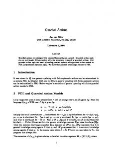
This new rule has the advantage that it behaves as rule Rswap if rule Rsub does not get enabled; it behaves as rule Rsub if rule Rswap does not get enabled and behaves as Rswap followed by Rsub if Rswap is enabled and that in turn does not disable Rsub. Hence, based on conditional actions, we have generated a single rule that behaves as three rules using traditional composition. In general, for a performance specification involving n rules, this approach introduces one rule as opposed to 2n rules. For circuit generation, the key insight here is that x0, x1, x2, y0, y1, y2, represent different versions of the state variables x and y within the same clock period. These versions are related to each other by cascading conditions and combinational logic which is derived semantically from the application of the rules chosen for composition: x1 = RswapEN ? y0 : x0; 2 1 1 1 x = RsubEN ? x - y : x ; 1 0 : y0; y = RswapEN ? x 2 1 y =y;
Rosenband’s Emphemeral History Registers (EHR)[8] provides a perfect hardware structure to capture this idea. We show the EHR circuit for the two rule composition case in Figure 1 below.
Before showing how we can generate this style of conditionally composed modular circuits, we present a more realistic design in the next section. This will make the challenge of modular composition and synthesis in the presence of multiple performance constraints more clear.
3. SPECIFYING SCHEDULES FOR A PIPELINED PROCESSOR Figure 2 shows a 4-stage pipeline for a toy processor which has only two instructions Add and Jz (Branch on zero). The stages are connected by FIFO buffers bF, bD and bE. In addition to the usual enq, deq, clear, and first methods, the bD and bE FIFOs also provide a bypass method to search the FIFO for a particular destination register and return a pair indicating if a match has been found, and if so, the associated value. The match flag is used for hazard detection in the bD FIFO and both components of the returned bypass pair are used to construct a true bypass from the bE FIFO. The processor has a total of 7 rules: F fetches an instruction and puts it in bF; D_add and D_jz decode the first instruction in bF and fetch the operands either from the register file or the bypass path and enqueue the decoded instruction into bD; the E rules execute the first instruction in bD and either enqueue the results in bE or, in case of a branch taken, clear the fetched instructions from bF and bD; WB writes back the value in the register file. In Figure 3 we give two implementations of the FIFO, one with a single element and another one which can contain up to two elements. function stall(src) = {matches, val} = bD.bypass(src); return matches; function bypassv(src) = {matches, val} = bE.bypass(src); if (matches) then return val; else return rf.read(src); F: when (true) => bF.enq(imem[pc]); pc := pc + 4; D_add: when (bF.first() == (Add rd ra rb)) & (!stall(ra)) & (!stall(rb)) => bD.enq(EAdd rd bypassv(ra) bypassv(rb)); bF.deq(); D_jz: when (bF.first() == (Jz cd addr)) & (!stall(cd)) & (!stall(addr)) => bD.enq(EJz bypassv(cd) bypassv(addr)); bF.deq(); E_add: when (bD.first() == (EAdd rd va vb)) => bE.enq(EVal rd (va + vb)); bD.deq(); E_jz_taken: when ((bD.first() == (EJz cd av)) & (cd == 0)) => pc := av; bF.clear(); bD.clear(); E_jz_nottaken: when ((bD.first() == (EJz cd av))&(cd != 0)) => bD.deq(); WB: when (bE.first() == (EVal rd vr)) =>
rf.write(rd, vr); bE.deq()
Figure 1: EHR’s for GCD The above rule examples only interact with registers. However, the notion of conditional actions, and hence the EHR style hardware structure naturally extends to modules and their interface methods. For example, two interface methods m.g and m.h are conditional methods that satisfy m.g $ m.h if their behavior can be explained as (i) m.g if only m.g is enabled, (ii) m.h if only m.h is enabled, and (iii) m.g followed by m.h if both methods are enabled.
Figure 2: 4-Stage Processor For this processor pipeline to work properly, it is important that the single element FIFO be able to enq and deq in a single cycle, otherwise at best alternate pipeline stages will operate concurrently. We also expect that rules that deq a FIFO should appear to execute before the rules that enq into the same FIFO (otherwise values could fly through the FIFO without ever getting latched – clearly not the intent of a pipeline stage). Similarly, for values to be bypassed from the execute stage to the decode stage the execute stage rule should appear to take effect before the decode stage rules fetch their operands. Based on these
observations a designer may want to specify the following schedule: Schedule1:
WB $ E $ D $ F
This schedule says: take a rule each from every group of rules (e.g. WB, Eadd, D_jz, F) and execute them in one cycle, giving the effect of WB, followed by E_add, followed by D_jz, followed by F. It is as if we want to combine all the rules in a particular order and produce a gigantic rule that makes all the stages move like a synchronous pipeline. Additionally, if any of the stages cannot execute, for example due to a stall condition, then if possible, the remaining subset of rules should continue to execute. Using conditional rules we will be able to achieve the effect of all subsets of these rules without actually generating the subset rules. For the sake of modularity we also want our design to work if we replace the one-element FIFO’s with the two-element FIFO’s. Assuming we have a two-element FIFO, consider the following schedule: Schedule2:
WB $ WB $ E $ E $ D $ D $ F $ F
This schedule says write back two instructions one after another, execute two instructions one after another, decode two instructions one after another and fetch two instructions one after another – all in one clock cycle. This is precisely the way a twoway superscalar processor is supposed to function. It should not come as a surprise that if the machine has to actually behave like a two-way issue machine then it would need more resources. Indeed we would see that implementing this schedule would require more interfaces on the FIFO’s and register files and, if sufficient storage in the form of registers is not provided, the design will result in modules whose methods may not be enabled properly. One Element FIFO: enq x = data :=x; full := 1; when (full == 0) deq = full := 0; when (full == 1) clear = full := 0; when (true) first = return data; when (full == 1) bypass src = if (full == 1) then return {data.rd == src, data.val}; else return {false, *}; when (true)
annotations on each method call and these annotations are further propagated inside modules until we reach registers, which are then replaced by EHR’s. Each of these renamed rules corresponds to one of the conditional actions we have previously mentioned.
4.1 The Ephemeral History Register The Ephemeral History Register (EHR) (see Figure 4) is a new primitive state element that supports the forwarding of values from one rule to another. It is called Ephemeral History Register because it maintains a history of all writes that occur to the register within a clock cycle. Each of the values that were written (the history) can be read through one of the read interfaces. However, the history is lost at the beginning of the next cycle. We refer to the superscript index of a method as its version or index. For example, write2 is version 2 of the write method. Each write method has two signals associated with it: x, the data input and en, the control input that indicates that the write method is being called and must execute to preserve rule atomicity. A value is not written unless the associated en signal is asserted. We can use the EHR in place of a standard primitive register element by replacing calls to the register read and write methods with calls to the EHR read0 and write0 methods. These interfaces behave exactly as those of a normal register if none of the other interfaces are being used.
4.2 Composition Using EHR Before explaining how to use the EHR to generate circuits that behave like composed rules we examine the requirements imposed by our approach. Suppose we are given rules R1 and R2 and want to achieve the effect of the composed rule R1,2. We replace rules R1 and R2 by rules R1’ and R2’ such that rule R1’ behaves the same as R1 in isolation, i.e. when rule R2’ does not execute (and similarly for R2’). However, when R1’ and R2’ both execute, then the behavior of the two rules executing should be the same as that of R1,2. Clearly, if R1 and R2 do not access common state, then R1’ and R2’ are equivalent to the original rules. However, if they do access common state, then reads and writes must satisfy the constraints in Figure 5.
Two Element FIFO: enq x
= if (full0 == 0) then data0 := x; full0 := 1; else data1 := x; full1 := 1; when (full1 == 0) deq = full0 := full1; full1 := 0; data0 := data1; when (full0 == 1) first = return data0; when (full0 == 1) clear = full0 = 0; full1 = 0; when (true) bypass src = if(full1=1)&(data1.rd = src) then return {1, data1.val}; else if(full0=1)&(data0.rd = src) then return {1, data0.val}; else return {0, *}; when (true)
0
write0.x
1
write0.en
0
write1.x
1
D
write1.en
0
write2.x
1
Q
read0
write2.en 0
writen.x
1
writen.en read1 read2 read3
Figure 3: FIFO Implementations readn+1
4. COMPOSITION USING THE EHR The Ephemeral History Register was introduced by Rosenband to provide greater control over scheduling of rules [8]. It provides new scheduling capabilities that cannot be achieved using just SC and CF analysis. We will first review the EHR’s functionality and then show how the EHR can be used directly to exploit the new style of composed rules. The innovative part of the EHR synthesis scheme is that it actually never generates the composite rules --- given the specification of a schedule it generates
Figure 4: The Ephemeral History Register For a given state element with initial value v0, the table specifies which values the rules must observe when reading the state element, and what element the state element should take after the rules have executed. We assume that R1 writes value v1 and R2 writes value v2 (which may be dependent on v1). The table makes clear that R2’ must observe any values that R1’ writes, and the final value must reflect the “last” rule that writes it. The last two table entries correspond to the execution of R1,2.
R 1’ executes
R2’ executes
R 1’ writes
Yes Yes No No Yes Yes Yes Yes
No No Yes Yes Yes Yes Yes Yes
No Yes
No No Yes Yes
R 2’ writes
R 1’ reads
R 2’ reads
Final value
v0 v0 v0 v0 v1 v1
v0 v1 v0 v2 v0 v2 v1 v2
v0 v0 No Yes No Yes No Yes
v0 v0 v0 v0
Figure 5: Composition Requirements We can use EHR’s to satisfy the requirements in Figure 5: 1) Replace all registers accessed by R1 and R2 with EHR’s. 2) Replace all read / write in R1 by calls to read0 / write0. 3) Replace all read / write in R2 by calls to read1 / write1. Each of the rules R1’ and R2’ execute individually as before. However, when executing together they exhibit the behavior of the composed rule R1,2. What makes this possible is that the EHR circuit allows rule R2’ to observe the values that are written by R1’. When R1’ does not execute (write0.en is 0), and the EHR returns the current state of the register to R2’ (read1). However, when R1’ does execute and writes a value to the register (write0.en is 1), then the value that the R2’ read interface (read1) returns is the value that was written by R1’ (write0.x). Such forwarding of values from one rule to another was not possible before the EHR was introduced. Effectively we have generated the conditional rule: R1,2: when (True) => t1 = R1(s); t2 = R2(t1); s := t2
This procedure can be generalized in a straightforward way to generate the composition of rules R0, R1, R2, R3, … Rn so that it appears as if the rules execute in the listed order. In almost all cases, the designer will also want all subsets of these rules to be composed in the same order. We can achieve this effect by replacing all read and write method calls in Ri by calls to readi and writei and by using a EHR with enough ports. This procedure works for the same reasons that it works in the case of two rules -a “later” rule in the composition order observes, via forwarding, any values that the next earliest rule writes.
4.3 Pruning and Other Optimizations The above algorithm does not always generate the optimal circuit (in terms of area and timing). For example, suppose R3, as part of a sequence R0, R1, R2, R3, is the only rule to access a register regonly3. The algorithm turns regonly3. into an EHR and provides R3 access to it via interfaces read3 and write3. However, since none of the other rules access the ports 0, 1, or 2 of the register regonly3 it is wasteful to have R3 tap the register at such a high index number. It could simply have accessed the register through the read0 and write0 interfaces. Thus, after each call to label the methods we should also call the PRUNE procedure which eliminates “gaps” in EHR references: PRUNE(R0, R1, …, Rn) = 1) access = { regi | regi is read or written in one of R0, …, Rn} 2) for i = n downto 0 do foreach r ∈access do if (r.readi and r.writei are unused) then decrement all access r.readj to r.readj-1 for j > i decrement all access r.writej to r.writej-1 for j > i
4.4 Modular Composition This section presents a new modular compilation algorithm for rule based designs. It takes as input a modular design with scheduling constraints and produces a new design that is functionally equivalent and is guaranteed to satisfy the scheduling requirements. Each scheduling constraint C takes the form S0 $ S1 $ S3 $ …, where each Sj is a set of rules. As previously described, we apply composition to module interface methods the same way as to rules. This gives us interface methods which can be composed to satisfy a constraint. Below we present the PROPCONSTRAINTS algorithm, which transforms the design to satisfy the constraint C. PROPCONSTRAINTS(C) = mToSched = ∅ ; foreach Si ∈ C do /** schedule the rule (methods) in C */ foreach Rj ∈ Si do mToSched = mToSched ∪CREATECOMPOSABLE(Rj, i); PRUNE({R | R ∈ C}); /*** construct interface requirements for modules ***/ foreach module m ∈ mToSched do S0 = ∅ ;S1 = ∅ ;S2= ∅ ; … foreach m.gi ∈ mToSched do // compose methods Si = Si ∪ m.gi; Cm = S0 x S1 …; PROPCONSTRAINTS(Cm); // recursively schedule each module CREATECOMPOSABLE(R, i) = mToSched = ∅ ; // set of methods to schedule R’ = R; // create a copy of R foreach method call m.g in R’ do // rename method calls R’ = R’ [m.gi / m.g]; // recurs if conditional interfaces are not provided if m does not provide conditional interfaces then mToSched = mToSched ∪m.gi; return mToSched;
4.5 Modular Composition Example The PROPCONSTRAINTS procedure transforms rules (and methods) so that they satisfy a scheduling constraint. The procedure creates conditionally composed module interface methods with new version numbers and alters rules (and methods) to make calls to these new methods. This section examines what these version numbers mean in the context of modules. As previously mentioned, the scheduling constraint for a 4-stage processor pipeline, excluding the jump taken rule is: WB $ {E_add, E_jz_nottaken} $ {D_add, D_jz} $ F
From these constraints, the PROPCONSTRAINTS procedure derives the following constraints for the FIFO interface methods: 0
0
1
bF: {first , deq } $ enq bD: {first0, deq0} $ enq1 $ bypass2 bE: {first0, deq0} $ enq1 $ bypass2
A reasonable jump-taken rule constraint is: WB $ E_jz_taken
From this constraint the PROPCONSTRAINTS procedure derives the following FIFO interface method constraints:
0
bF: clear bD: first0 $ clear1 bE: {first0, deq0}
The solution is to produce “separate” interfaces for the different constraint groups. In the above example, this would result in the following interfaces:
Let us first examine what the new FIFO interface means if we only satisfy one constraint, e.g. {first0, deq0} $ enq1 $ bypass2. The behavior of the action methods (enq and deq) can be explained by conditional composition, where ti’s represent the conditional values that result from the MUX structure: t-1 = s; if (m.deq0.en) then t0 = m.deq(s); else t0 = t-1; 1 1 0 1 1 0 if (m.enq .en) then t = m.enq(t , m.enq .x); else t = t ; 1 s=t
The two read methods (first and bypass) return values based on the temporary variables in this expression. The first0 method returns a value based on the t-1 state and the bypass2 method returns a value based on the t1 variable. This new FIFO interface has the effect of performing the composition of the interface methods if they are simultaneously enabled, e.g. if first0, deq0, enq1, and bypass2 are all called, then the behavior is as though first0 and deq0 execute, followed by enq1 (which observes state changes that are made by deq0), followed by bypass2 (which observes state changes made by both deq and enq). If only a subset of the methods execute, we still obtain the correct compositional behavior. For example, if deq0 and bypass2 execute (and not enq1), then bypass2 directly observes the state that deq0 produces (deq0 produces t0, bypass observes t1, and since enq is not executing: t1 = t0). Thus, the behavior of a module interface with a single constraint is clear.
4.6 Multi-Constrained Modular Composition A final step in giving the designer complete flexibility is to allow many sequences of rules to be composed. For example, the designer may want three composition sequences to be generated: (i) R0, R1, R2; (ii) R2, R3; and (iii) R3, R0. The most straightforward way to accomplish this is to create copies of rules that occur in multiple sequences and to then call the PROPCONSTRAINT procedure on each sequence. After PROPCONSTRAINT completes we construct a circuit and scheduler for the design using the normal Bluespec synthesis. This combines composition sequences as well as rules that were unconstrained. Although this method always produces correct circuits, it can introduce critical paths that the designer might not have intended. We can illustrate this problem via the processor example from the previous sub-section in which we had one set of constraints that did not contain the branch taken rule, and one constraint that does contain the branch taken rule. If we call the PROPCONSTRAINTS procedure for each constraint and then merge the resulting interfaces, we obtain the following conditional FIFO methods: 0
0
0
1
bF: {first , deq , clear } $ enq bD: {first0, deq0} $ {enq1, clear1} $ bypass2 0 0 1 2 bE: {first , deq } $ enq $ bypass
As an example of an unindent combinational path, values might be passed from clear0 to enq1 in the bF FIFO. Although functionally correct, this solution could produce a design with unsatisfactory cycle time. One option is to have a scheduler disallow both of these methods from being called concurrently, and marking the path as a false-path. However, an alternate solution that better fits a conventional synthesis flow exists.
bF: {firsta0, deqa0} $ enqa1 bD: {firsta0, deqa0} $ enqa1 $ bypassa2 bE: {firsta0, deqa0} $ enqa1 $ bypassa2
| clearb0 | firstb0 $ clearb1 b0 b0 | first $ deq
A register circuit with the following interface is shown below: EHR_split: {reada0, writea0} $ {reada1, writea1} $ {reada2, writea2} | b0 b0 b1 b1 b2 b2 {read , write } $ {read , write } $ {read , write } 0
writea0.x
1
writea0.en
0
writea1.x
1
D
writea1.en
0
writea2.x
1
0
PRIMUX 0
reada1 reada2 reada3
0 1
writeb0.en
0
writeb1.x
1
writeb1.en
0
writeb2.x
1
writeb2.en
reada0 readb0
0
writea2.en
writeb0.x
Q
readb1 readb2 readb3
Figure 6: EHR with Split Note: values are only forwarded from writea* to reada* and from writeb* to readb*, and not from writea* to readb* or writeb* to reada*. With the EHR, this “split” structure can be generated for arbitrary conditional method interfaces.
5. RESULTS AND EVALUATION To implement the new flow we created the EHR state-element in Verilog and imported it, along with its interface scheduling properties into Bluespec. We then created the designs, including FIFO’s, RF’s, etc. in Bluespec using registers as the only primitive state elements. We then transformed the design into a new design according to the procedure outlined in Section 4 for each scheduling requirement. The resulting design was then fed through the Bluespec compiler to produce RTL Verilog, which was then synthesized using Synopsys Design Compiler to generate area and timing numbers for the TSMC 0.13µm G process. We generated area and timing numbers for two different timing constraints to illustrate numbers for an area and a timingconstrained synthesis run. We also simulated each design to measure functional performance. Figure 7 shows the results for GCD designs to meet 3 different scheduling constraints. The first design is the original design and does not incorporate any transformations. The second design composed Rswap $ Rsub, and the third design was scheduled to satisfy the constraint: Rswap $ Rsub $ Rswap $ Rsub. As is expected, as more rules are composed, fewer cycles are required to compute results. Similarly, the critical path increases as more rules are composed. In spite of this for the 5ns constrained synthesis the two schedules speedup the GCD by 1.06 and 1.98 but its area increases by 52% and 350%, respectively because much of the logic needs to be duplicated and the adder logic increases dramatically in size because of the timing constraint.
GCD Input
Measure
No Constr.
Rswap X Rsub
Rswap X Rsub X Rswap X Rsub
cycles cycles
91 117
78 101
39 51
10ns constr. Area (µm2) 10ns constr. Timing (ns)
5221 10
6479 10
13705 10
5ns constr. Area (µm2) 5ns constr. Timing (ns)
5909 4.54
9003 5.00
26638 5.3
Input 1 Input 2
Figure 7: GCD Results Figure 8 shows the results for a 4-stage processor pipeline. In addition to an unconstrained design (the traditional Bluespec flow), we synthesized the designs with the following four schedules , where E* = {E_add, E_jz_nottaken}: Schedule1:
WB $ E $ D $ F
Schedule2:
WB $ E* $ D $ F WB $ E_jz_taken
Schedule3:
WB $ E* $ D $ F $ E_jz_taken
Schedule4:
WB $ WB $ E* $ E* $ D $ D $ F $ F WB $ WB $ E_jz_taken $ E_jz_taken
We had discussed Schedule 1 earlier in Section 3. Architects usually optimize the branch-taken case differently from the branch-not-taken case and this is what is reflected in Schedules 2 and 3. In Schedule 2 we exclude the branch-taken rule from the first performance specification expecting to make the critical path shorter than Schedule 1 because fetch cannot observe the branch target in the cycle that the branch is resolved. This effectively splits the access to the PC between the fetch and branch resolution stage (see section 4.6). This eliminates the critical path from Schedule 1 but in turn should have a slightly higher cycle count since branch taken and fetch cannot execute in the same cycle. In Schedule 3 we move the branch taken rule to the “end of the cycle”. This eliminates the critical path from branch-taken through fetch. However, this means that the branch taken observes the results of the decode stage – effectively we have moved the branch resolution into the decode stage. Hence the critical path becomes: execute an add instruction, bypass it into the decode stage and compare it with 0 to see if the branch is taken. This is a long critical path, but is a design used in many processors. Finally Schedule 4 is the 2-way superscaler version of Schedule 2. Bench. (cycles)
Design
Area 10ns (µm2)
Timing 10ns (ns)
Area 1ns (µm2)
Timing 1ns (ns)
No Constr. Schedule1 Schedule2 Schedule3 Schedule4
18525 9881 11115 9881 11115
1 element fifo: 24762 25362 25001 25180 25264
5.8 7.5 6.6 8.0 6.8
33073 34161 34511 34896 36037
1.6 2.2 1.9 2.6 1.9
No Constr. Schedule2 Schedule4 Schedule4+Fix
18525 11115 7410 7410
2 element fifo: 32240 7.4 32535 8.4 45296 10.0 40180 9.9
39033 47084 62649 62053
1.9 2.63 4.7 3.0
Figure 8: 4-stage Processor Results
We synthesized the designs using one and two element FIFO’s as pipeline stages since a two-element FIFO is required for a superscalar implementation to perform well. A simple benchmark loop with arithmetic operations and conditional branches was run on all designs. Although this benchmark was very small, it provides an idea of what the relative throughput for each processor pipeline is. The execution time can be computed by multiplying the cycle time and the cycle count. We compute the speedups by treating the unconstrained Bluespec schedule with 1ns constrained synthesis as the base case. As a reference for the timing results, we show timing numbers for some of the key processor components in Figure 9. These numbers are approximate since each synthesis run selects slightly different implementation. However, it is clear that unless we further pipeline the design, no design can have a cycle time of much less than 1.6ns since we must sequentially get the decode FIFO output (Clk to Q – about 0.3ns), pass through an adder in the execute stage (about 0.9ns), pass through at least one level mux (0.3ns) and then satisfy setup time (0.1ns). Component
Propagation Delay
32 bit addition 32 bit increment 32 bit compare to 0 2-1 MUX (32 bits wide) Clk to Output + Setup Time
0.9ns 0.6ns 0.6ns 0.3ns 0.4ns
Figure 9: Component Delays As expected, Schedule 1 does much better than the unconstrained implementation because the standard Bluespec compiler can only schedule alternating stages to execute in each cycle. It shows a speedup of 1.36 with only a 3% increase in the area. Schedule 2 improves on this by showing a speed up of 1.40 with a 4% increase in the area. We really did not expect an improvement with Schedule 4 with one-element FIFOs! We should note that these experiments could be performed just by changing the scheduling specifications; the algorithms we presented earlier ensure that the correctness of the designs is maintained in this process. The results for two-element FIFOs in Figure 8 show the cycle count improvements for the superscalar design but also significantly worse clock speeds. The speedup in the best case is only 1.33 because the penalty of clearing the pipeline after each branch taken is relatively high in the superscalar design. Somewhat disturbingly, the cycle time for the superscalar design is more than twice that of the single element FIFO composed design (4.7ns vs. 1.9ns). In an optimal implementation we would expect the superscalar design to have a cycle time of only slightly more than the composed pipeline (about two MUX stages, or about 0.6ns). Below we discuss several simple changes we can make to the circuit generation and the FIFO implementation to reduce the superscalar cycle time from 4.6ns to 3.0ns (about 0.5ns within optimal). Note: This is the only design for which we altered code to improve cycle times – all other designs were directly derived from the original processor code and transformed using the conditional composition algorithms. The first change is a simple circuit transformation shown in Figure 10. This is a simple logic transformation that Synopsys design compiler currently does not perform, but which is easy to add to the Bluespec compilation. In this case, the Bz1_taken
signal is on the critical path. In the original design (on the left side of the figure) the next PC computation for the second fetch in the superscalar fetch stage cannot be computed until the earlier branch is resolved. By simply moving logic across the MUX we can improve this path. Old PC
PC + 1
Bz1 Taken
Old PC
⇒ +1
+1
PC + 1
+1
Bz1 Taken
New PC
New PC
Figure 10: Moving Logic Across a Mux A more interesting change that had a dramatic impact on the cycle time of the superscalar design is that we slightly changed the two element FIFO specification. These changes do not alter the behavior of the FIFO, but imbed high-level logic that we have about the FIFO into its circuits. For example, we know that after dequeueing from the FIFO twice, it will be empty. Since the write back stage in the superscalar design will always execute twice if the FIFO contains two valid elements (and once if it contains only one element), the execute stage does not need to check that the FIFO between the write back and execute stages is empty. Such a check can add one or two MUX’s to the critical path (0.6ns). We can achieve this effect by rewriting the enq method as follows (the changes to this method are highlighted in italics): enq x
= if (full0 == 0) then data0 := x; full0 := 1; full1 := 0 else data1 := x; full1 := 1; when ((full1 == 0) || (full0 == 0))
Clearly, these changes do not alter the behavior of the design: We know that if full0 is 0, then full1 is also always 0, so it is safe to add the check of (full0 == 0) to the method’s implicit condition. Similarly, we can write the value 0 to full1 if the FIFO is empty and we are enqueueing a value since the value will be placed in the “0” slot. Although these changes do not change the functionality, they have the impact of allowing constants to be effectively propagated through the pipeline – for example after this change, the execute stage logic is optimized via constant propagation to no longer need to check if the FIFO it is enqueueing in is full. Another example of this type of change is to the FIFO clear method. Again we highlight the change in italics. Obviously, the data values can have any value after the FIFO is cleared. However, by setting the data0 value during a clear method call to the value it would have after a deq, the logic that reads from the FIFO can be optimize: regardless of what the “first” rule in a stage does (deq or clear), it always moves data1 into data0, so the “second” rule to execute always knows what the “new” value in data0 will be and hence can directly look at the data1 register. Again, by simply adding this line of code which clearly doesn’t change FIFO functionality we embed some high-level knowledge into the design. The result is that a MUX stage for one of the FIFO’s is removed from the critical path. Note: this optimization works in the processor execute stage where the “first” execute rule always executes. However, this optimization does not improve timing for the decode rules because the “first” decode rule might stall. clear = full0 := 0; full1 := 0; data0 := data1; when (true)
These types of changes allowed us to reduce the cycle time from 4.6 to 3.0ns. The remaining 0.5ns can be obtained through similar changes but they become counterintuitive since one needs to keep track of when data is available and how mux’s are introduced. Instead, at that point it would be more reasonable to rewrite the design as a superscalar design. It is important to recognize that a decision to rewrite the design with “superscalar” in mind is not due to a short-coming in the synthesis methodology that we present here. As designers we simply have high-level knowledge that the compiler does not have. Without this knowledge, the compiler must be conservative. An interesting future approach to this work might be to use user-assertions to guide the compilation process. For example, an assertion could be added that if FIFO slot “0” is empty, then FIFO slot “1” is also empty.
6. CONCLUSION We presented a new synthesis algorithm for guarded atomic actions based on conditional rule composition and analyzed the efficiency of such an approach on several designs. We leveraged previous research on design transformation through rule composition as well as the EHR to create a practical framework that has a well founded theoretical foundation, but is also practical in that it eliminates the rule explosion that previously was required for such transformations. Our algorithms create efficient implementations that satisfy multiple performance constraints for both rules and modules. The experimental results show that interesting architectures can be rapidly generated by simply changing scheduling constraints. Additionally, many of the resulting designs have efficient circuits. In the cases where circuits are non-optimal, the designer can usually use high-level knowledge to make minor changes to the design to achieve the expected circuit timing.
7. REFERENCES [1] Arvind, Nikhil, R.S., Rosenband, D.L. and Dave, N., Highlevel Synthesis: An Essential Ingredient for Designing Complex ASICs. in ICCAD, (San Jose, 2004). [2] Baader, F. and Nipkow, T. Term Rewriting and All That. Cambridge University Press, Cambridge, UK, 1998. [3] Bluespec, Inc., Benchmarking of Bluespec Compiler Uncovers No Compromises in Quality of Results (QoR) www.bluespec.com/images/pdfs/InterraReport042604.pdf [4] Dave, N., Designing a Reorder Buffer in Bluespec. in MEMOCODE, (San Diego, 2004). [5] Gupta, S., Dutt, N., Gupta, R. and Nicolau, A., SPARK: a high-level synthesis framework for applying parallelizing compiler transformations. in VLSI Design, 2003. Proceedings. 16th International Conference on, (2003), 461-466. [6] Hoe, J.C. and Arvind Operation-centric hardware description and synthesis. Computer-Aided Design of Integrated Circuits and Systems, IEEE Transactions on, 23 (9). 1277-1288. [7] Lis, M.N. Superscalar Processors via Automatic Mircoarchitecture Transformations, M.Eng. Thesis, EECS, Massachusetts Institute of Technology, 2000. [8] Rosenband, D.L., The Ephemeral History Register: Flexible Scheduling for Rule-Based Designs. in MEMOCODE, (2004). [9] Terese Term Rewriting Systems. Cambridge University Press, Cambridge, UK, 2003.