HARTs: High Availability Cluster Architecture with Redundant TCP Stacks* Zhiyuan Shao, Hai Jin, Bin Chen, Jie Xu, and Jianhui Yue Huazhong University of Science and Technology, Wuhan, 430074, China Email:
[email protected] Abstract Improving the availability of services of is a key issue for survivability of a cluster system. Lots of schemes are proposed for this purpose. But most of them aim at enhancing only the service-level availability or application specific. In this paper, we propose a scheme called High Availability with Redundant TCP Stacks (HARTs), providing connection-level availability by exploring the redundant TCP stacks for TCP connections at the server side. We present our performance experiment results on our HA cluster prototype. From results, we find the configuration of one primary server with one backup server running on separated 100Mbps Ethernet has acceptable performance to support the server side applications while delivering high availability.
1. Introduction With the popularity of using clusters of computers built of COTS components instead of high-end supercomputers, more and more efforts need to be done to solve the reliability problems of the cluster system. For a typical TCP connection with one client and one server [3], the failure of a TCP connection can be either the failure of the client connection or the failure of the server connection. The former one can be solved by increasing the reliability of the client’s computer or by simply restarting the client. The TCP connections at server side are always shared by multiple clients simultaneously. The failure of a TCP connection for a busy server will not be so simple as restart of the server. The most ideal way to implement the high availability of a TCP connection is socket migration. If we can migrate the socket connection at server side when the server fails, the availability of TCP connection can be improved. Transparent migration of the sockets associated with a migrating process has been done inefficiently in previous _______________
works. This is due to the complexity of the connection status and the huge cost involved replacing the full-grown IPv4 architecture [7]. Although running replicas of a same task can be easily implemented by putting the replica of the original task into redundant computer components and let them run. To build the replicas of a process with communication, we face the problems such as how to replicate the communications. Multicasting [19] is one choice, but the source code of the process should be largely modified. This is not acceptable if the cost is inhibitive or the source code is not available. As TCP connection is strictly one-to-one connection. To make multiple replicas of a TCP connection means that we have to deal with the communication semantic with one-to-multiple paradigm. In this paper, we propose a scheme called High Availability with Redundant TCP Stacks (HARTs) to improve the availability of TCP connections. With HARTs, at least two server nodes working in active-active mode, maintaining the redundant TCP connection stacks. Any failure in one of the server nodes will not interrupt the TCP connections. As the servers working in active-active mode, there is no need to perform checkpointing during the fail-free. In case of server failure, there is no need to perform socket migration to rescue the TCP connection, as a redundant TCP connection can continue working without takeover time. HARTs also makes the redundant TCP connections as single networking. There is no need to modify any code of user application at both the client side and the server side. Furthermore, no efforts need to be done to modify operating system kernel at the client side. In section 2 we briefly give some related works to enhance the availability or fault tolerance of the connections. The architecture of HARTs is described in section 3. Details of our HARTs system are elaborated in section 4. Experiment results are presented and discussed in section 5. We end our paper with conclusions.
2. Background
*
This work is supported by National Defense Advanced Research Project under grant 413150401.
FT-TCP [1] is a scheme for transparent recovery of a
crashed process with open TCP connections. A wrapper around the TCP layer intercepts and logs reads by the process for replay during recovery, and shields the remote endpoint from failure. Although the possibility of recovery from a connection failure is provided in this scheme, the recovery requires backup all the logs related to the connection for the reinstating of the server side’s TCP stack. As an uncertain span of time is required for the replaying, FT-TCP has to be limited as a method of providing fault tolerance not high availability. In a system with implemented FT-TCP, each packet belonging to a connection should be backup in a logger. To confirm the success of logging, responses cannot be sent out until a message indicating the accomplishment of logging is received. In this way, the fault tolerance is guaranteed. But the communication bandwidth is largely sacrificed. Also, the logger becomes a new single point of failure in the system. Fault Resilience in web-server cluster [15] proposed a solution of achieving fault resilience of the clusters dedicated to provide all kinds of web services. In their system, web services are cataloged as stateless request for web surfing and stateful requests for session based services. The corresponding methods of implementing fault resilience are proposed. This project comfortably realized fault resilience in the web-server clusters, but it is very specified and limited to the scope of the clusters, which designed to be web-servers. The twin server protocol proposed in their scheme introduces an unpredictable time span before the final result of a client’s request sent out. The longer the client’s stateful request, the longer the client should wait before he receives the response. Fine-grained failover using connection migration is a failover architecture that enables migrating HTTP connections within a pool of servers [5]. It replicates per-connection soft transport and application state. The connection migration is initiated only by the new server in the case such as failure or overload of origin server [14]. The architecture adds a HTTP-aware module at the transport layer that extracts information from the application data stream to be used for connection resumption. The design also depends on the information in the application data stream. Socket Cloning [10] is a scheme proposed for load-balancing the workload of the server nodes in a cluster dedicated for web services. The key idea is to migrate workload of a heavy-loaded server node to a lighter-loaded server node or where the cached replication of the requested document resides by cloning the socket. After cloning, the incoming packets of a request are firstly sent to the original server node and then to the server node where the cloned socket resides by a mechanism
resembling TCP splicing [6]. Responses generated by the cloned socket are directly sent out by using TCP handoff [2][8]. It is the cloned socket that deals with the subsequent requests while the original node keeps track with the status changing. By using this scheme, the workload can be balanced and the communication overhead incurred by transferring the cached blocks by using cooperative caching is minimized. As the original node does nothing after socket cloning except for being aware of status changing, the cloned socket is also a single point of failure although high reliability is not the key issue in web services.
3. Connection-based Cluster Architecture
High
Availability
In a classic cluster architecture, a portal server lies between the outside clients and the inside real servers. All connections from the clients are firstly sent to the portal rather than directly to the real server nodes that provide services. After having received these incoming connections, the portal server will deliver them among the real server nodes by using some load-balancing algorithms. Software packages, such as LVS [16], used on the portal node are also an active research topic. The real server nodes deal with the incoming service requests. If a real server node crashes, the portal node gets this information by periodically diagnosing their status. The following requests will not be delivered to the crashed server node until it is recovered. By this scheme, classic cluster provides high availability to its services. But the connections connected to the real server node before the crash is simply lost. The granularity of availability a classic cluster provides is the services not the connections. And by using these clusters to achieve high reliability, most of the schemes are worked in an active-standby mode where time cost in failover is always very high. In order to satisfy the connection-based availability granularity for cluster system and reduce the failover time, we proposed new high availability cluster architecture, illustrated in Figure 1. The key objective of our scheme is that the primary and the backups are working in an active-to-active mode. If any of these component fails, an identical replica will continue the work without or with little stop. For achieving this objective, there must be a server node (any Backup Servers in Fig.1) should take over the server node (Primary Server in Fig.1) that actually make connections with the outside world in case of its failure. This means the connection state of the Primary Server must be restored. Each of the computer nodes in HA cluster have two NICs, eth0 and eth1. There are also two logically
independent networks, the private network and the public network. All the eth1 of computer nodes are connected to the private network, whereas all the eth0 to the public one. Private Network eth1
eth1
eth1
eth1
Client Primary ServerBackup Server1 Backup Server2Backup Server3 eth0 eth0 eth0 eth0 (inactive) (inactive) (inactive) Public Network
Figure 1 HA Cluster Architecture The IP addresses bound to the eth1s are private IP addresses belonging to a same subnet. The major functionality of this private network is to provide a channel for the internal communications among cluster nodes. Regarding the eth0, although they are all physically connected to the public network, only the eth0 of the primary server is activated. Its IP address is visible to the Internet and can be uniquely addressed. The eth0 of the other server nodes (the Backup Servers) are all inactivated during the fail-free run. Actually, all the Backup Servers in the HA cluster except for the Primary Server are not isolated from the outside world. As they regard the Primary Server as their gateway, they can actively make their own connections with the outside world. When a connection between a client and the cluster is initiated, the packets belongs to this connection are delivered to the Backup Servers by the Primary Server via the private network. All the responses generated by the Backup Servers are sent back to the Primary Server. During the period of the connection, the Primary Server will filter all the unnecessary responses and guarantee just one response from the cluster. If the Primary Server crashed while the connection is still on the fly, one of the Backup Servers will be elected, without losing generality, say it Backup Server1 in Fig.1. The elected Backup Server will strive to establish its role as the new Primary Server. During the establishment, the eth1 IP Address of Backup Server1 will change to be the eth1 IP address of the crashed Primary Server. The eth0 of Backup Server1 will be brought up, and the IP address also changes to that of eth0 of old Primary Server. This action can be accomplished by IP faking. After IP faking, the new Primary Server is established as it is shown in Figure 2. To simplify our discussion, we assume that after receiving the data stream from the client, all of the servers in the cluster will elicit identical responses. This assumption can be justified by most of the applications running in the cyberspace.
Private Network eth1
eth1
eth1
eth1
Client Primary ServerBackup Server1 Backup Server2 Backup Server3 eth0 eth0 eth0 eth0 (inactive) (inactive) (activated) Public Network
Figure 2
HA Cluster with a Crashed Primary
4. Priniciple of Redundant TCP Stacks We now discuss the principle of redundant TCP stacks from two aspects. In the case of system in the fail-free status, we focus our discussion on the principle of redundant TCP stacks about how to maintain the normal connections. While for the failover situation, we discuss how the connections are retained and continue their operations while any of the servers in HA cluster fails.
4.1 Scenario 1: Fail-free With redundant TCP stacks, there are multiple servers in a HA cluster system participating one side of a same connection. The first thing we need to address is to maintain connection while it can be regarded as normal connection from both of the viewpoints of the backups and the primary. The connection status must be synchronized in these multiple units. This issue includes how to synchronize the sequence numbers and how to synchronize the operations. 4.1.1 Synchronizing the TCP sequence numbers. Considering a typical TCP connection, when a client wants to establish a TCP connection with a remote server, he sends out a SYN packet with a client-side Initial Sequence Number (ISN) J. After receiving the SYN packet from client, the server replies back a SYN&ACK packet which contains the server-side ISN K and acknowledge number J+1. These are the first two steps of the 3-way handshaking mechanism to establish a TCP connection. After that, all the packets belonging to this connection are tagged with a sequence number with offset from K and J. Otherwise, the TCP stacks will discard the packet. In our HA cluster system, we use multiple independent server nodes instead of one autonomous server. After receiving the SYN packet, all the server nodes should response to establish a connection. They also need to be synchronized during the remaining communications. The first issue we need to address is how to synchronize the sequence numbers used by the server nodes for a specific connection. That is, if the primary node crashed during the
connection, one of the backup nodes who takes over the role of the primary node should send out packets tagged with the sequence number originated from the ISN generated by the primary node. Only by this way, the packets sent out by this new primary node can be recognized by the TCP stacks of the clients. An intuitive method is to record the ISN generated by the primary server as well as the offset from the sequence number of the latest packet to that ISN, backup these values periodically to the backup servers. If the primary server crashed, its heir uses the backup record to modify its outgoing packets. Although this method fits the sequence number control logic of the TCP stacks, unnecessary communication overhead is introduced and the determination of the time span between the backup server nodes remains a big problem. We solve this problem by rendering the TCP stacks of the servers some modifications. The SYN packet from a client initializing a connection contains just an ISN and either none or a meaningless acknowledge number. When capturing this packet firstly by the primary server, we fill the unused field of acknowledge number with a “secure sequence number” which has no confliction with other connections and modify the reserved field in the packet with a specific flag K. The modified SYN packet is then delivered to the both primary server and the backup servers with modified TCP stack. After receiving this SYN packet, the modified TCP stacks use the “secure sequence number” as the ISN for the later communications. This procedure is illustrated in the Figure 3. SYN(J)
Synchronizating Layer
SYN(J) K(flag)
Client
SYN(K) ACK(J+1) SYN(J) K(flag) SYN(K) ACK(J+1) SYN(J) K(flag) SYN(K) ACK(J+1) SYN(J) K(flag) SYN(K) ACK(J+1)
Primary Node Backup Node1 Backup Node2 Backup Node3
SYN(K) ACK(J+1)
Figure 3 Synchronizing TCP Sequence Numbers Using this scheme, no further communications between the primary and backup servers for the sequence number synchronization are required. The elected backup node as new primary server node can simply send out its packet with correct TCP sequence numbers. 4.1.2 Synchronizing the operations. A simply solution is to permit all the packets created by the primary node
and relay all the packets generated by the backup nodes without discrimination and processing. This solution has two problems. Firstly, the public network in our HA cluster system will be overloaded. Secondly, as the server nodes process their communication independently, the faster server node (incurred by the its lighter workload or fast processing ability for heterogeneous nodes) will make the client runs faster. Thus, the slower server node will be chocked because it could not keep pace with the status change of the connection. That is, in order to synchronize TCP stacks, the communication speed is determined by the slowest node not the fastest. In our scheme, a synchronization layer is deployed between the TCP stacks and the outside world. After receiving the SYN packet from a client, the connection information is stored in a hash table item by a hash function with client’s IP address, port number, and the server port number. Each server node taking part in this connection is added to this item as a linked list. The data structure denoting server node in the linked list contains several important fields, which are critical to our algorithm. max_seq_num is the maximum sequence number of the packets sent by the node; max_ack_num is the maximum acknowledge number the node issued; window_size is the current advertised window number. When the response of one server node reaches the synchronization layer, the connection it belongs to is addressed and the server node structure is found subsequently by matching the IP addresses and port numbers it contains. Whether this packet should be relayed or not is decided by an algorithm, called send when minimum updated (SWMU). For the implementation purpose of SWMU algorithm, the hash table item must contain following fields: t_max_seq_num is the maximum sequence number among all the server nodes; t_min_seq_num is the minimal sequence number of all the nodes; t_max_ack_num is the maximum acknowledge number; t_min_ack_num is the minimal acknowledge number; t_window_size is the minimal advertised window number the server nodes currently advertised. When a packet arrives from a server node, the max_seq_num field of that node structure is updated. This action incurs redetermination of the t_max_seq_num and t_min_seq_num of the hash table. If and only if t_min_seq_num is updated, the packet could be sent out with some modifications. Figure 4 give an example of 4 server nodes for the SWMU algorithm. We assume that their initial sequence number are all K, which means t_max_seq = t_min_seq = K initially. Packet1 from node1 comes first, and it set max_seq_num field to be K1. The t_max_seq_num field is also updated to be K1. Then, packet2 and packet4 arrive, and the length of these 2 packets is longer (K2=K4>K1).
Then, t_max_seq_num is update to be K2. The t_min_seq_num of this connection is NOT updated when all these 3 packets arrive. Thus, all of them will not be relayed. But the arrival of packet3, which belongs to node3, will make things different. It will update t_min_seq_num from K to K1 (K2>K3>K1). K3
K1 packet1 K
node1
packet2 K
node2
K
packet3
node3
4.2 Scenario 2: Failover In this part we will describe how the connections can be retained when the primary server crashed, and how the heir of the primary restore all the information for the connections.
K4
K2
client, to synchronize the connection, we can simply control the ACK numbers of the outgoing packets and leave the data in these outgoing packets unsynchronized.
packet4 K
node4
Figure 4 An Example of SWMU Algorithm According to their arrival time, we know that the updated time for t_min_seq_num is the time when the slowest server node responses. And it is also the time to deliver the packet. In the above example, simply relaying packets is also improper. Packet3 should be firstly trimmed to be ended at K1, and the outgoing packet must undergoing NAT [17] before relaying out. There still remains an exception. When a server pulls data in, there is no updating of t_min_seq_num. On the contrary, the t_min_ack_num undertakes the role of t_min_seq_num and the outgoing packets contains the minimal acknowledge number. We still omitted something in our discussion above. The HA cluster is consisted of many servers. Although receiving data from some client is their common requirements, which already be comfortably fulfilled by Redundant TCP Stack technology, in some configurations, different servers are also assigned to different tasks. There are two ways for the servers to advance their individual private communications. Although in our HA cluster, only the primary server has its eth0 active and connected to the “public network”, the back-end servers also have the ability to communicate with the clients while regarding the primary server are their gateway. That means, all the servers in the HA cluster can make connections with the clients to transfer data for their own tasks. If the primary server crashed during the lifetime of these “private” connections, these connections will not lose as TCP is robust enough and the newly elected primary server will change the IP address of its eth1 to be that of the “dead” primary server and have its eth0 brought up. It is also possible for the servers to have the requirement of transferring data with some client using the same connection, which is already “synchronized” by our synchronizing layer. In this case, we can design some regulations in the synchronizing layer to make it fit these requirements. For example, if the whole HA cluster runs in a “Pull” mode in the “synchronized” connection with the
4.2.1 Fault detection. In order to achieve the failover, the first thing we have to do is to determine which server node is undergoing a failure. Heartbeating [9] is the most common way to detect failure in cluster system. But this scheme is in most cases only very useful in hardware failures. We build up fault diagnose module in the software running in these servers. They are very simple and efficient so that when any software fault is detected, they can report to the synchronizing layer and then it is the synchronizing layer who can decide what to do the next. In our HA cluster system, if the dead unit is a backup server, there is no influence to the primary server. If the primary server is failed, a new primary server must be elected. To elect one live backup server from the multiple ones, there are many election algorithms can be employed [4][11]. For simplification, we use election algorithm in our system to find out a live server having the minimal last byte of IP address as the new primary server node. As there are so many proposals and implementations in the field of fault detection and this is not the main point in our paper, we will not discuss this topic in the very detail. 4.2.2 Connection failover. The traditional way to achieve failover is the check-pointing technique. The critical information of primary server is stored in the backup servers. When the primary fails, one of the backups will continue the service from the latest checkpoint. In our scheme, to avoid harming the fail-free performance and reduce failover time, we do not backup any information during normal operation. We use the following way in our scheme to decide from where the elected back-end node continues. When the HA cluster system works in the fail-free mode, the primary server knows the status of all the backup servers, but any of the backup servers knows nobody except itself. The only thing the back-end PU can record is its own connection status during the operation. We use an example to elaborate how the connections failover to a backup server. During the fail-free run, we assume there is a backup server, node2, who is eligible to be a new primary. We will describe what happened after the failure of primary server and how node2 takes up the
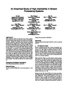
Figure 5 shows the throughputs under different cluster configurations. In Fig.5, there exist a sudden decline in the throughput curves when the packet size is 1537 and 3073. This decline is introduced by IP fragment and resembling mechanisms. As our tests are conducted in Ethernet with MTU of 1500, a packet sized either 1537 or 3073 contains a small IP packet when fragmented. It is this small IP packet that degrades the throughput. 70 60 50 40 30 20 10 7681
6913
6145
5377
4609
3841
3073
2305
1537
0 769
We use Netpipe-2.4 [11] as our benchmark to test our HARTs system. Each node in our cluster system is Pentium III 450 CPU with 128MB memory and dual 100Mbps NICs. The operating system is Redhat Linux with a kernel version 2.4.2. To test the performance of individual TCP connection, both ends of a TCP connection in Netpipe work in a ping-pong model, one receives after one sends and vice versa in the other end of connection. The size of the packets used in these experiments starts from an intialvalue. After a predefined looptimes of these experiments, the packet size increased by an increament. The loops continue until the packet size reaches a predefined uppervalue. In our experiment, we define the intialvalue to be 1 byte, the increament to be 256 bytes, the uppervalue to be 8193 bytes, and the looptimes to be 400. The throughput for each specific size of packet is the
5.1 100M-Shared Experiments and Results
1
5. Performance Evaluation
mean value of the throughput of all experiments, and the final result is obtained by 3 times of repeated testing. The number of backup servers in the HA cluster system can be varied. With different number of the backup servers, the performance results are also different. We use 1P to represent the configuration of one primary server, 1P1B one primary server plus one backup server, 1P2B one primary server plus two backup servers and 1P3B one primary server and three backup servers. Our experiments are conducted under two different network configurations. First, we connect all the NICs of the servers and the client to a single 100Mbps hub. We call this configuration 100M-Shared. Second, we construct a private network with 100Mbps hub, and the public network with a 100Mbps Switch. We call this configuration 100M-Separated. In our experiment platform, about 101 units of the CPU time equal to 1 second of our real world. This value applies to all figures related to the CPU time in this paper.
Throughput(Mbps)
role of the new primary. The only information node2 has is how long it runs. When primary server fails and the newly elected primary node becomes node2, node2 have to know the information of the other living nodes. By using IP address faking, the IP address bound to the NICs of node2 is modified after the election. The automatically retransmitted packets by the TCP stacks of the other living nodes will arrive node2 after the election. Thus, it is very easy for node2 to obtain the connection status information of the living others. It uses SWMU algorithm to decide which packet needs to be relayed by comparing all the packets. The failure of any backup server will not cause any election or any change in the cluster system. If a backup server fails, the rest server nodes in the cluster system simply drop down the dead server’s connection information. But if the slowest backup server crashed during the operation, and the packet of this backup server is not sent out, there is still a problem. Even though the other servers are still in operation, the whole cluster system comes into a status of malfunction. This is incurred by SWMU algorithm, as the packet with minimal sequence number will never arrive in this situation. To solve this problem, the primary server has to decide carefully when to drop a connection information structure of a dead server especially as it belongs to the slowest server one. In our scheme, we first decide whether a server owns the minimal sequence number when the information of a backup server is to be dropped. If not, the connection information is simply dropped. Otherwise, the status must be recorded first and then, the primary server selects a retransmitted packet from the other nodes with the latest sequence number the deleted server had.
Packet Size(Bytes) 1P
1P1B
1P2B
1P3B
Figure 5 Throughput of HA Cluster under 100M-Shared Configuration In the configuration of one primary and one backup, the throughput degrades from that of one server configuration. With the increasing number of server nodes in cluster, the network throughput decreases. The performance loss dues to the latency introduced by sequence number synchronization and our SWMU algorithm. The network saturate degree also has a side effect to the performance.
With the increasing of the number of the servers, these two reasons of performance loss become substantial. For the configurations of multiple server nodes in our cluster, with the increasing packet size, the throughput improvement becomes smaller, and the final result is a fairly stable one compared with one server configuration. This is because with the increased server nodes, communication overhead turns heavier, and the saturate degree of the shared network increases. By using tcpdump, the possibility of packet retransmission from the backup servers also increase, and this puts more burden to the network. As the result, the throughput gain by transferring larger packets is buried by the network overhead. We measured the server node idle CPU time to justify whether the server nodes is busier or not. As the idle CPU time in a single ping-pong test is so small to be compared, we summed all the idle CPU time in the loop of 400 times of ping-pong tests. Figure 6 illustrates the test results for these experiments.
server. Thus, in the cluster configuration of 1P1B, the primary node will be busier than one single server node while the backup node will work in almost the same CPU overload as that of one single server node. By adding more server nodes to the cluster, the primary server node becomes busier and no change for backup nodes. It is due to the SWMU algorithm that incurs this heavier CPU workload.
5.2 100M-Separated Experiments and Results Figure 7 shows the throughput results under different cluster configurations. The characteristics of results obtained in Fig. 5 are still applicable to Fig. 7. But the performances of the clusters with one or more backup servers with 100M-seperated configurations are better than those with 100M-Shared configurations. 70 60
450
50 Throughput(Mbps)
400
CPU IdleTime(101=1s)
350 300 250 200
40 30 20
150 100
10
50
Figure 6 Servers Idle CPU Time under 100M-Shared Configuration In our experiment, the status of different backup servers in the same primary-backup configuration is identical. Thus, only one curve is shown to represent the status of all the backup server configurations. In Fig. 6, with the increasing of server nodes, the idle CPU time in both primary servers and backup servers increases. The throughputs gained by using multiple server nodes are much lower than by using single autonomous server node. This means that the cluster of multiple server nodes will need more time than a single server while transferring the data of same size. We must consider both the total idle CPU time and the throughput rate. Considering the configuration of 1P1B, the throughput is nearly half of using single server. The time spent by transferring the same size of data is doubled than that spends by one single server. At the same time, the CPU idle time of the primary node is less than the twice of CPU idle time of single server, the CPU idle time of the backup node is very close to the twice of CPU idle time of single
8193
7681
7169
6657
6145
5633
5121
4609
4097
3585
3073
2561
2049
1537
1
8193
7681
7169
6657
6145
5633
Primary(1P1B) Primary(1P2B) Primary(1P3B)
1025
PacketSize(Bytes)
5121
4609
4097
3585
3073
2561
2049
1537
1025
1
513
Primary(1P) Backend(1P1B) Backend(1P2B) Backend(1P3B)
513
0
0
PacketSize(Bytes)
1P
1P1B
1P2B
1P3B
Figure 7 Throughput of HA Cluster under 100M-Separated Configuration The gap of the performances between the 100M-seperated configurations and the 100M-shared configurations tells us how much the network saturation burdens the throughput, as it dose not exist in the “public network” in the 100M-seperated configurations. The experiment results of server idle CPU time under different cluster configurations are presented in Figure 8. The same patterns are applied as that of the 100M-Shared configuration. But as the throughput is increased, both primary servers and backup servers become busier.
6. Conclusions In this paper, we discussed the redundant TCP stacks and the related innovative cluster architecture. By using these techniques, the traditional “one to one” paradigm of TCP connection is changed and connection gratuity high available services can be obtained. We also implemented a prototype. Experiments on this prototype under various
cluster configurations are performed. 350
[6] 300
CPU IdleTime(101=1s)
250
[7] 200
150
100
[8]
50
8193
7681
7169
6657
6145
5633
5121
4609
4097
3585
3073
2561
2049
1537
513
1025
1
0
PacketSize(Bytes)
Primary(1P) Backend(1P1B) Backend(1P2B) Backend(1P3B)
Primary(1P1B) Primary(1P2B) Primary(1P3B)
Figure 8 Servers Idle CPU Time under 100M-Separated Configuration In the experiments, we observed that the retransmitted packets from the back-end processing units put heavy burden on both the network and the CPU of the primary server. If we can filter the meaningless retransmission, the network throughput will be improved. The performance of our cluster system in the current status is not so optimal. By carefully measure the network throughput and the CPU utilizations we advocate that a specially designed router or a dedicated computer is needed as a portal so that the software of synchronizing layer and SWMU can be put on them. At the same time, the availability of the portal can be guaranteed from hardware or by another backup.
[9] [10]
[11]
[12]
[13]
[14]
References [15] [1]
[2]
[3]
[4]
[5]
L. Alvisi, T. C. Bressoud, A. El-Khashab, K. Marzullo, and D. Zagorodnov, “Wrapping Server-Side TCP to Mask Connection Failures”, Proceedings of INFOCOM 2001. M. Aron, D. Sanders, P. Druschel, and W. Zwaenepoel, “Scalable content-aware request distribution in cluster-based network servers”, Proceedings of the USENIX 2000 Annual Technical Conference, June 2000. K. Ghose, “A Comparative Study of Some Network Subsystem Organizations”, Proceedings of the IEEE 1998 International conference on High Performance Computing (HiPC'98), pp. 436-443. Y. Huang and P. K. McKinley, “Group leader election under link-state routing”, Proceedings of the IEEE Internation Conference on Network Protocols, Atlanta, Georgia, October 1997 D. Maltz and P. Bhagwat, “MSOCKS: An architecture for
[16] [17]
[18] [19]
transport layer mobility”, Proceedings of IEEE Infocom'98, Mar. 1998. D. Maltz and P. Bhagwat, “TCP slipcing for application layer proxy performace”, IBM Research Report 21139, IBM Research Division, 1998. R. Nasika and P. Dasgupta, “Transparent migration of distributed computing processes”, Proceedings of Thirteenth International Conference on Parallel and Distributed Computing Systems. V. S. Pai, M. Aron, G. Banga, M. Svendsen, P. Druschel, W. Zwaenepoel, and E. Nahum, “Locality-aware request distribution in cluster-based network servers”, ACM SIGPLAN Notices, Vol.33, No.11, pp.205–216, Nov.1998. Robertson, “Linux-HA Heartbeat System Design”, Proceedings of 2000 ALS conference. Y.-F. Sit, C.-L. Wang, and F. Lau, “Socket Cloning for Cluster-Based Web Server”, Proceedings of IEEE Fourth International Conference on Cluster Computing, Chicago, USA, September 23-26, 2002. S. Singh, J.F. Kurose, “Electing ‘Good’ Leaders in Distributed Systems,” Journal of Parallel and Distributed Systems, Vol.23, 1994, pp.184-201. Q. O. Snell, A. Mikler, and J. L. Gustafson, “Netpipe: A Network Protocol Independent Performace Evaluator”, Proceedings of IASTED International Conference on Intelligent Information Management and Systems, June 1996. C. Snoeren, D. G. Andersen, and H. Balakrishnan, “Fine-Grained Failover Using Connection Migration”, Proceedings of 3rd USENIX Symposium on Internet Technologies and Systems (USITS), 2001. F. Sultan, K. Srinivasan, and L. Iftode, “Transport Layer Support for Highly-Available Network Services”, Proceedings of HotOS-VIII, May 2001. C.-S. Yang and M.-Y. Luo, “Realizing Fault Resilience in Web-Server Cluster”, Proceedings of the 13th ACM/IEEE Conference on High Performance Networking and Computing (SC 2000). W. Zhang, “Linux Virtual Server for Scalable Network Services”, Proceedings of Ottawa Linux Symposium 2000. D. L. Herbert, S. S. Devgan, C. Beane, “Application of network address translation in a local area network”, Proceedings of the 33rd Southeastern Symposium on System Theory, 2001, pp.315-318 Y. Rekhter and P. Gross, Application of the Border Gateway Protocol in the Internet, RFC 1268, Oct. 1991. S. Johnson, F. Jahanian, “Experiences with group communication middleware”, Proceedings of the International Conference on Dependable Systems and Networks (DSN 2000), 2000, pp.37-42