ELECTRONICS’ 2007
19 – 21 September, Sozopol, BULGARIA
HAZARDOUS GAS MONITORING USING VI SERVER Georgi Todorov Nikolov, Boyanka Marinova Nikolova, Marin Berov Marinov Faculty of Electronics and Technologies, Technical University of Sofia, Studenstki Grad, TUSofia, block 1, room 1366, 1797, Sofia, Bulgaria, e-mail:
[email protected],
[email protected],
[email protected] Today there is a great deal of interest in the development of gas monitoring systems for application of gas leaks, detection of harmful gases in mines, home safety, exhaust gas monitoring etc. In all this fields of investigation, a key matter is the need of flexible and practical virtual instruments, a way to easily expose the gas sensors to hazardous levels of gas concentration. This paper presents a conceptual architecture for a versatile, flexible, cost efficient, portable system for monitoring the gas presence in the air. The software platform – in terms of virtual instruments – is developed under LabVIEW programming environment and to be specific VI Server technologies. VI Server features for internet connectivity are used in order to cover a large monitoring area.
Keywords: Hazardous and combustible gases, Monitoring Systems, Portable USB DAQ, Taguchi Gas Sensors, Virtual Instrumentation. 1. INTRODUCTION Gas monitoring has become an integral part of many environmental protection and safety programs. Because of increased attention to risks posed by gas, systems that simply annunciate an alarm condition are no longer adequate. Gas monitoring programs now comprise employee training, data analysis, multiple alarm strategies, self-diagnostic system verification, and documentation. Data communication has also become a fundamental component of system design and operation as well. And finally, environmental factors help guide the program selection process [3]. Gas risk management requires a comprehensive look at the hazards of gas leaks. Properly designed gas monitoring systems provide suitable hardware in combination with data management and diagnostics capability to custom fitting a solution for managing, rather than reacting to, gas leaks. On the other hand, data acquisition in analytical chemistry has also reached a very sophisticated point, especially with computerized instrumentation' which can yield enormous quantities of very reliable chemical data. One of the most interesting features of modem instrumentation is the number of variables, which can be measured on a single sample. Visualization is the most important cognitive interface between researcher and data and the computer also has aided that tremendously. In many cases visualization may not be adequate without a theoretical framework to interpret the display. Consequently, the demand for more sophisticated tools to be used in the interpretation of such data has rapidly increased.
93
ELECTRONICS’ 2007
19 – 21 September, Sozopol, BULGARIA
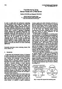
The goal of the presented virtual system is to acquire, transmit, process, archive, alarm and visualize the required signals for gas monitoring, as well as to build automatic reports. 2. LABVIEW METHODS FOR INTERNET CONNECTIVITY From many years, the National Instruments (NI) LabVIEW offers the different connectivity features, upgraded periodically according modern trends in communication technologies. As most popular can be mentioned [2, 4]: Web-enabled VIs (Remote and Embedded Panels), Network shared variables (Since LabVIEW v8), VI Server, XML, TCP/IP, UDP, ActiveX and .NET, AppleEvents, Pipes (available in OpenG packages), DataSocket, AppletVIEW, etc. In the process of design, as more adequate to a developed gas monitoring system are considered and selected three technologies (fig.1): Web-enabled Vis (Remote Panels), VI Server and DataSocket. Taguchi Gas Sensors
DataSocket Server
USB DAQ 6009 Workstation S erver LabVIEW
Alarm 1
VI Server
LabVIEW NI DAQmx
Data
LV Web Server Alarm 2 LabVIEW
Internet
Fig. 1. Deployment diagram of virtual system
Remote panels are technology for web pages served up by LabVIEW's built-in web server. With this LabVIEW web server, it is possible to dynamically create web pages with images of a VI's front panel on the fly, without the need for any special coding in block diagrams. On the other side a distance located user can simply type a URL in the web browser and instantly see an image or control a VI [4]. The DataSockets (and the new shared variables on Windows) are protocols for effective network connection that easily share data between NI-based applications. With DataSockets, the user can easily hook any front panel control or indicator into the way, so other VIs or applications can publish or subscribe to that control. The VI Server is a powerful feature in LabVIEW that offers the capability of programmatically accessing features in LabVIEW like opening and running VIs, changing the color or value of a front panel object, printing the front panel, and so on.
94
ELECTRONICS’ 2007
19 – 21 September, Sozopol, BULGARIA
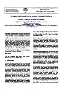
With VI Server, it is possible programmatically: load a VI into memory, run it, and then unload the VI, without the need to have it statically linked as a subVI in the block diagram; dynamically run a subVI that gets called at runtime, by only knowing its name and connector pane structure (this is known as calling a VI by reference); change properties of a particular VI, such as the size and position of the front panel window, whether it is editable, and so on; make LabVIEW windows move to the front of the screen; from the block diagram, call a subVI without waiting for it to finish executing; dynamically change the attributes (properties), such as color and size, of a front panel object. The VI Server exposes its functionality in LabVIEW through block diagram functions from Function Palette. It also allows its functionality to be accessed in Windows from external programs (e.g., a Visual Basic program or macro) and from a remote LabVIEW VI over TCP/IP. Continuously gas monitoring applications that require storing and processing lots of data, often needs working with databases, tying together the LabVIEW labs to a common network, and implementing remote client access. To accomplish this external tools like LabSQL or the Database Connectivity Toolset can be used. 3. DEPLOYMENT DIAGRAM OF MONITORING SYSTEM The gas monitoring system block diagrammed in the fig. 1, is designed to measure and monitor hazardous gases, response when dangerous concentration are achieved, and signalize to local and distance operators. The computer monitors and controls all system equipment. The USB DAQ module communicates with the Taguchi gas sensors and measure gas concentration. The application runs inside LabVIEW and uses following graphical programming technologies (pointed out as software components): • LabVIEW Web Server – for continuously monitoring of gas level from distant users by using standard Web-browser; • NI DAQmx device drivers – for software control of measuring devices; • VI Server – manages communications to the number of remote clients (operators) and automatically generates alarm signals on distance computers; • DataSocket Server – provides an on-line graphical view of the measured data; • Processes and archives data in a database. The main task of the VI Server is to run several client applications available to remote computers and automatically activate its front panels for monitoring by the user. If the hazardous gas concentration achieved critical levels the light and audio signals is used in addition. 4. DESIGN OF VIRTUAL SYSTEM FOR LP GAS MONITORING 4.1 Hardware design The gas monitoring system consists of Taguchi gas sensor TGS 26xx series from Figaro, humidity sensor HIH3610 from Honeywell and USB Data Acquisition Module DAQ-USB-6009 from National Instruments – fig. 2. The operational amplifiers connected as voltage followers are needed because of low input impedance
95
ELECTRONICS’ 2007
19 – 21 September, Sozopol, BULGARIA
of the DAQ – 155kΩ [8]. For instance in fig. 2 a pre-calibrated module LPM – 2610 for Liquefied Petroleum Gases (LPG) is used [5, 7]. Based on the concentration entered in the sensor module, the DAQ send a voltage in the range of 0,8 to 4 volts to the LabVIEW program, which corresponds to a concentration range of 300 to 10000 ppm depending of gas monitored. The capabilities of introduced system are summarized in Table 1. VC (3) HIH 3610
VRH
(2) (1)
(2)
(5)
+
1/2 (2) LM124W
(1) LPM2610
(3)
(4)
(3)
-
Vout (1)
(11)
(4)
Vtemp
(9)
+
1/2 (8) LM124W
(7)
-
GND (1) +5 V (31) AI 0+ (2) AI 0- (3) AI 1+ (5) AI 1- (6) AI 2+ (8) AI 2- (9) AI 3+ (11) AI 3- (12) DAQ USB-6008/9
Fig. 2. Hardware Design Table 1
Gas
Range, ppm
IsoButane C4H10 300-10000 ±5 % Methane CH4 300-10000 ±5 % Hydrogen H2 300-10000 ±5 % Ethyl Alcohol CH2H5OH 300-10000 ±5 % Resolution of Analog Inputs Humidity Measurement Range Voltage Supply Power Consumption
Alarm level (LEL), ppm 1,5 - 4 1800 1,4 – 3,5 5000 1 – 3,1 4000 0,8 – 2,7 3300 2,4 mV 5% - 95% ± 2 %; 5V 72,4 mA (362 mW)
DAQ Voltage, V
4.2 Software design The measurement hardware is controlled by software using specific drivers. The recently introduced DAQ drivers NI-DAQmx improve the performance of data acquisition applications and save a considerable amount of development time [9, 10]. One feature of these drivers is the Application Programming Interface (API), which is the same across both device functionality and device families. API requires only a small number of functions to expose the majority of DAQ functionality [10]. This means that all of the functionality of a multifunction device is programmed with the same set of functions (analog input, analog output, digital I/O, and counters). Another significant feature of the NI-DAQmx architecture is Measurement Multithreading. Because NI-DAQmx is multithreaded, multiple data acquisition operations can occur simultaneously, significantly improving the performance of the applications that contain multiple operations. It also greatly simplifies programming such applications.
96
ELECTRONICS’ 2007
19 – 21 September, Sozopol, BULGARIA
Block diagram of introduced gas monitoring system is shown on fig. 3. As can be seen from the figure the base DAQmx functions are used to control the measurement process. Virtual analog channels are implemented by Create Channel.vi (AI-VoltageBasic). Synchronization and timing are managed by Timing.vi and Start Task.vi functions. The measured data are acquired by Read.vi (Analog 1D, Wfm, Nchan, NSamp), which is drive in While loop in order to read multiple times. In the end of the data flow the DAQmx Clear Task.vi and Simple Error Handler.vi are placed.
Fig. 3. Block Diagram of Gas Monitoring System
The control of digital channel is accomplished in similar manner. This digital channel is used to switch on local alarm system (siren, LED atc.) when LEL of gas concentration is reached. On the bottom of the figure 3 is placed icon (subVI) of LP Gas VI Server that controls distribution of gas monitoring data itself. When the target gas concentration reach the LEL this subVI is activated.
a)
b) Fig. 4. Block Diagrams of VI Server (b) and client (a)
The block diagram of LP Gas VI Server is quite simple and is shown on fig.4b. The first function Open Application Reference.vi activates LabVIEW program of distance computer with pointed IP address.
97
ELECTRONICS’ 2007
19 – 21 September, Sozopol, BULGARIA
Next function Open VI Refrence.vi used file path control to find client application, and opens LP Gas Client. To call the specified methods (OpenFP and RunVI) of this client appli-cation the Invoke Note utilities are used. The Invoke Note opens Front panel and start application. Ones executed the client application immediately connects its indicators to monitoring system via DataSocket connection. If the received data is great than LEL of target gas than the alarm (highspeakers, or other indicators) is turned Fig. 5. Front panel of the client on. The front panel of created client application with appropriately placed indicators is shown on fig. 5. 5. CONCLUSION In this paper is proposed a gas monitoring system based on Taguchi gas sensors combined with the possibilities of the VI Server for programmatically opening and running Vis installed in distance computers. Every function, client and server, are implemented using LabVIEW, with a small exception of DataSocket connectivity. The customers are fully capable of managing and even expanding the system to monitor more signals from different sensors. Remote hardware units can be placed far away from a computer and communicate through USB-hub, for example. A LP gas sensor connector allows easy replacement of the module for the purpose of periodic sensor renewal. This connector enables easy installation and replacement of the module into the gas detectors’ board. This same monitoring system can be used for various gases detected by sensors of this family by simply changing the module and without software changes. 6. REFERENCES [1] Nikolova, B., M. Marinov, G. Nikolov, Air Quality Monitoring System, ELECTRONICS’2006, Sozopol, 2006 [2] Stoyanov, I., G. Nikolov, B. Nikolova, “Remote Access Methods for Virtual Instumentation”, ELECTRONICS’2003, Sozopol, 2003, book 4, pp 103-108 [3] General Monitors, Fundamentals of Combustible Gas Detection, www.generalmonitors.com, 2005. [4] Travis, J., J. Kring, LabVIEW for Everyone: Graphical Programming Made Easy and Fun, Prentice Hall, 2006. [5] FIGARO, LPM - 2610 – pre-calibrated module forLP Gas , Product Information, 03/2002. [6] FIGARO, Figaro Gas Sensors 2000 Series, Product Catalogue, 2006. [7] FIGARO, TGS 2610 - Technical Information for LP Gas Sensors, Product Information, 2001. [8] National Instruments, USB-6008/6009 User Guide and Specifications, July 2005. [9] National Instruments, NI-DAQmx Key Concepts, September 2005, 371407A-01. [10] National Instruments, NI-DAQ™mx Help, February 2007, 370466J-01.
98