In a video conferencing setting, people often use an elongated meet- ing table with the major axis along ... simultaneously capture all the participants and provide the meeting context for the ... conferencing images. We call the class of warping.
HEAD-SIZE EQUALIZATION FOR BETTER VISUAL PERCEPTION OF VIDEO CONFERENCING Zicheng Liu and Michael Cohen Microsoft Research One Microsoft Way Redmond, WA 98052, USA ABSTRACT In a video conferencing setting, people often use an elongated meeting table with the major axis along the camera direction. A standard wide angle perspective image of this setting creates significant foreshortening, thus the people sitting at the far end of the table appear very small relative to those nearer the camera. This has two consequences. First, it is difficult for the remote participants to see the faces of those at the far end, thus affecting the experience of the video conferencing. Second, it is a waste of the screen space and network bandwidth because most of the pixels are used on the background instead of on the faces of the meeting participants. In this paper, we present a novel technique, called Spatially-VaryingUniform scaling functions, to warp the images to equalize the head sizes of the meeting participants without causing undue distortion. In addition, we show a specially designed five-lens camera to capture, stitch, and warp images in real time without sacrificing resolution. Finally, we show that the SVU scaling functions can also be applied to 360 degree images to improve video conferencing experience when an omni-directional camera is used.
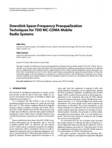
1. INTRODUCTION In a standard video conferencing setting, the field of view of the video camera is usually large enough so that it can simultaneously capture all the participants and provide the meeting context for the remote participant. One drawback is that the people sitting at the far end of the table appear very small relative to those nearer the camera. Figure 1 shows a cylindrical projection of a meeting room which is equipped with a video conferencing system. The images of the people sitting at the far end of the table are very small compared to the two people at the front. The remote participants would have to switch views in order to see the people at the far end thus affecting the video conferencing experience. Furthermore, it is a a waste of the the screen space and network bandwidth because most of the pixels are used on the background instead of on the faces of the meeting participants. In this paper, we present a novel technique, called SpatiallyVarying-Uniform scaling functions, to warp the images to
equalize the head sizes of the meeting participants without causing undue distortion. In order to obtain enough resolution for the people sitting the far end of the table, we have designed a five-lens camera where each camera has different field of views, and we are able to capture, stitch, and warp images in real time.
Fig. 1: A cylindrical projection of a conference room. Compare to the results of our real-time warping function in Figure 8.
2. SPATIALLY VARYING UNIFORM SCALING FUNCTION In this section, we describe a parametric class of image warping functions that attempt to equalize people’s headsizes in the video conferencing images. We call the class of warping functions Spatially Varying Uniform Scaling functions, or SVU scaling for short. These functions locally resemble a uniform scaling function to preserve aspect ratios, however, the scale factor varies over the image to create the warp. The class of conformal projections can provide local uniform scaling, however, they introduce rotations which are visually disturbing. This led us to the SVU scaling functions that avoid rotations at some costs in terms of introducing shear. We will use the example shown in Figure 1 to describe the SVU scaling. The images are captured in real-time using a five-lens device we describe later. After stitching, this provides us with a full 180 degree cylindrical projection panoramic image. We would like the warping function to be such that it zooms up the center more than the sides while locally mimicking a uniform scaling. We would like to avoid rotations (as might appear in conformal projections), particularly keeping vertical lines vertical. The warp we initially describe induces
some vertical shear, thus slanting horizontal lines. We describe at the end of this section a modification that corrects for much of this at some cost to aspect ratio near the top and bottom boundaries.
For any pixel (x, y) in the source image, let (x� , y � ) denote its new position in the warped image. We have � x x� = r(x)dx y�
0
= Tt (x) + r(x) ∗ (y − St (x))
(3)
This is the forward mapping equation for the SVU scaling function. The SVU scaling function is not a perfect uniform scaling everywhere. It is easy to prove that the only function that is a perfect uniform scaling everywhere is a uniform global scaling function. 2.1. Horizontal Distortion Correction Fig. 2: The warping function is determined by two sets of curves: source (green) and target (red) curves.
The user, via a simple user interface, provides the parameters for the SVU scaling function. The user is asked to define two cubic curves (see Figure 2). These two source curves define common (real world) horizontal features such as the tops of people’s heads, and the edge of the table. A factor, α also chosen by the user determines how much the image is warped. Let y = St (x) and y = Sb (x) be the equations of the top and bottom source curves respectively. Two target curves (where points on the source curves will move to) are determined by the source curves and α. If we denote the equation of the line between the end points of St (x) as y = yt (x), and the equation of line connecting the bottom source ends as y = yb (x), then the top target curve is Tt (x) = (1−α)St (x)+αyt (x), and Tb (x) = (1−α)Sb (x)+αyb (x). An α = 0 will leave the image untouched. An α = 1 will pull pixels on source curves to the lines between the end points. For example, the four curves shown in Figure 2 consist of two green source curves and two red target curves. Given any vertical scanline x as shown in Figure 2, let A, B denote its intersections with the source curves, and A� , B � the intersections with the target curves. The SVU scaling function will scale AB to A� B � . Let r(x)
= =
||A� B � || ||AB|| Tt (x) − Tb (x) St (x) − Sb (x)
(1)
We scale the line vertically by r(x), and to preserve aspect ratio we also scale the scanline horizontally by r(x). Therefore, the total width of the new image, w� , becomes � w � w = r(x)dx (2) 0
where w is the width of the source image.
Fig. 3: The vertical scale function.
While the SVU-scaling function maintains vertical lines as vertical, it distorts horizontal lines. The distortions are smallest between the source curves and largest near the top and bottom. Scenes often contain horizontal surfaces near the top or bottom, such as a table and the ceiling on a room for which the distortions may be noticeable (see Figure 1). To minimize this problem we relax the uniformity of the scaling and nonlinearly scale each vertical scanline. The portion of the image between the source curves is scaled by r(x) as described above. The portions outside the source curves are scaled less in the vertical direction. The horizontal scaling remains the same (i.e., r(x)) to maintain the straightness of vertical lines. To maintain continuity, the vertical scaling function smoothly transitions as it crosses the source curves. Consider the vertical line in Figure 2. Denote g(y) to be the vertical scale factor at any point y on this vertical line (see Figure 3). Note that g(y) is dependent on x. g(y) is controlled by two parameters s and ω. The portion of the vertical scanline more than ω/2 distance from the source curves is scaled by r(x) between the source curves and by s outside the source curves. The three constant segments are glued together by two cubic splines in [St −0.5ω, St +0.5ω] and [Sb − 0.5ω, Sb + 0.5ω]. Each cubic spine has ends with values s and r(x) and a slope of 0 at both ends.
The parameter ω controls the continuity at the source curves. For example, if the scene is discontinuous at the source curves, one can choose a very small ω without noticeable artifacts. In the special case when s = r(x), g(y) becomes a constant which is what we assume in deriving Equation 3. 3. HALF-RING CAMERA ARRAY
tion one. At run time, we use a look up the table to perform color blending for each pixel.
3.1. SVU Scaling the Stitching Table Applying the SVU scaling function to the stitched image would result in a loss of resolution. Instead, we warp the stitch table itself, and generate a new table. During this offline warping, we use bilinear interpolation to fill in zoomedup regions to avoid losing resolution. At run time, we generate the warped images by a simple look-up in the pre-warped stitch table. The complete stitching, blending, and warping are computed in a single frame time. 4. RESULTS
Fig. 4: The half-ring camera.
Fig. 5: Images from the five cameras.
If we directly apply our warping function, the extreme enlargement of the far people will be very blurry due to the limited resolution of the image in this area. To solve this problem, we have built a special "half-ring" video camera consisting of five inexpensive (< $50each) fire-wire video cameras daisy-chained together (See Figure 4). A single IEEE 1394 fire-wire delivers five video streams to the computer. The resolution of each camera is 640 by 480. Each camera has a different lens. Figure 5 shows the five images directly from the five video cameras. The center camera has the smallest field of view (about 25 degrees) to provide enough resolution for the distance. The field of view of the two cameras next to the center are 45 degrees, with the outer having the largest field of view (60 degrees). Together, they cover 180 degrees with enough overlap between neighboring cameras for calibration and image stitching. We use well-known techniques to calibrate these cameras and compute the homography between the cameras [12, 6, 7, 11]. We then stitch the individual images together to generate a 180 degree cylindrical image (see Figure 1). Computation overhead is reduced at run time by pre-computing a stitch table that specifies the mapping from each pixel in the cylindrical image to pixels in the five cameras. For each pixel in the cylindrical image, the stitch table stores how many cameras cover this pixel, and the blending weight for each camera. Blending weights are set to one in most of the interior of each image with a rapid fall off to zero near the edges. Weights are composed with an over operator where the higher resolution pixel is composed over a lower resolu-
For the image in Figure 1, Figure 6 shows both the source and target curves with α = 0.3. Figures 7 through 10 show the results of using the SVU scaling function. Figure 7 shows the result of applying the SVU scaling function without correcting horizontal distortion. Figure 8 shows the result after correcting for horizontal distortion. Finally we show some results with different α. Figure 9 shows the result with α = 0.2, and Figure 10 shows the result with α = 0.4. During live meetings, we store multiple tables corresponding to different α’s so that one can change levels in real time. The size of the stitched image is approximately 300 by 1200 pixels. During warping, we keep the image width the same, and as a result, the image height decreases as we zoom up. The frame rate is about 10 frames per second on a CPU with a single 1.7GHZ processor.
Fig. 6: The source curves and the target curves with α = 0.3.
Fig. 7: SVU scaling without horizontal distortion correction.
Fig. 8: SVU scaling with horizontal distortion correction.
Fig. 12: After applying SVU-scaling to Figure 11. Fig. 9: SVU scaling with α = 0.2.
Fig. 10: SVU scaling with α = 0.4.
5. APPLICATION TO THE IMAGES CAPTURED BY OMNIDIRECTIONAL CAMERAS Recently, there has been a lot of interests on using omnidirectional cameras for video conferencing [4, 9, 8, 1, 3, 10, 5]. An omni-directional camera is usually placed at the center of the table so that it captures the entire meeting room. For an elongated meeting table, it also has the problem that people’s head sizes are not uniform due to the distances to the camera. Figure 11 shows an image captured by an omnidirection camera at the center of a meeting table. The table size is 10x5 feet. The person in the middle of the image appears very small compared to the other two people because he is further away from the camera. SVU-scaling functions can be applied to such images to equalize people’s head sizes. Figure 12 shows the result after applying SVU-scaling function. As the sensor technology rapidly advances, people are designing inexpensive high resolution (over 2000 pixels in horizontal resolution) omni-directional video cameras [4]. But due to network bandwidth and client’s screen space, only a smaller-sized image can be sent to the client. The SVUscaling function provides a much better way to effectively use the pixels to maximize the user’s experience. Notice that by applying SVU-scaling function to the high resolution image, the zoomed up pixels in the smaller-image (which is sent over the network) will not look blurry because there are enough pixels in the original higher resolution image.
Fig. 11: A meeting room captured by an omni-directional camera.
6. CONCLUSION We have presented a class of warping functions to address perceptual problems when viewing wide-angle images. One important application of these SVU scaling functions is teleconferencing. We have shown their effectiveness at reducing the exaggerated depths between near and distant participants while limiting distortion of each individual. The head-size equalization improves visual perception, and provides a way to more effectively use the network bandwidth and screen space. We have described a special five-lens video camera to capture and warp the images in real time. In addition, we
have shown that the SVU scaling functions can also be applied to 360 degree images captured by an omni-directional camera in a video conferencing room. One of the cameras in our current five-lens video camera does not focus well. The images captured by that camera look blurry. In the future, we would like to replace that camera. We are working on an automated color balancing to get the images to match better. We are also developing techniques to automatically find the table boundaries and generate the warping table [2]. 7. REFERENCES [1] M. Aggarwal and N. Ahuja. High dynamic range panoramic imaging. In IEEE Conference on Computer Vision and Pattern Recognition (CVPR), 2001. [2] Y. Chang, R. Cutler, Z. Liu, Z. Zhang, A. Acero, and M. Turk. Automatic head-size equalization in panorama images for video conferencing. In IEEE International Conference on Multimedia and Expo, Amsterdam, The Netherlands, July 2005. [3] S. Coorg, N. Master, and S. Teller. Acquisition of a large posemosaic dataset. In IEEE Conference on Computer Vision and Pattern Recognition (CVPR), pages 872–878, 1998. [4] R. Cutler, Y. Rui, A. Gupta, J. Cadiz, I. Tashev, L.-W. He, A. Colburn, Z. Zhang, Z. Liu, and S. Silverberg. Distributed meetings: A meeting capture and broadcasting system. In ACM Multimedia, 2002. [5] R. A. Hicks and R. Bajcsy. Catadioptric sensors that approximate wide-angle perspective projections. In Workshop on Omnidirectional Vision, pages 97–103, 2000. [6] M. Irani, P. Anandan, and S. Hsu. Mosaic based representations of video sequence and their applications. In International Conference on Computer Vision (ICCV’95), pages 605–611, 1995. [7] S. Mann and R. W. Picard. Virtual bellows: Constructing high quality images from video. In First IEEE International Conference on Image Processing (ICIP’94), pages I:363–367, 1994. [8] S. Nayar. Catadioptric omnidirectional camera. In IEEE Conference on Computer Vision and Pattern Recognition (CVPR), 1997. [9] S. Nayar. Omnidirectional video camera. In DARPA Image Understanding Workshop, 1997. [10] S. Nayar and A. Karmarkar. 360x360 mosaics. In IEEE Conference on Computer Vision and Pattern Recognition (CVPR), pages II388–392, 2000. [11] R. Szeliski and H.-Y. Shum. Creating full view panoramic image mosaics and environment maps. In Computer Graphics, Annual Conference Series, pages 251–258. Siggraph, 1997. [12] Z. Zhang. Flexible camera calibration by viewing a plane from unknown orientations. In International Conference on Computer Vision (ICCV’99), pages 666–673, 1999.