Santiago Domınguez Barrios, Juan Carlos López López. Departamento de Ingenierıa Electrónica. E.T.S.I. Telecomunicación, Universidad Politécnica de Madrid.
Heterogeneous Systems Design: a UML — Based Approach � Santiago Dom´ınguez Barrios, Juan Carlos L´opez L´opez Departamento de Ingenier´ıa Electr´onica E.T.S.I. Telecomunicaci´on, Universidad Polit´ecnica de Madrid Ciudad Universitaria s/n. 28040 Madrid, Spain E-mail: @die.upm.es
> 100 pag.
Java
>1GByte >1MTRT
ObjVHDL
C++
>100Klines
C
VM code µ P Assembly language
DSP Assembly language
VHDL FPGA CPLD FPLD
Abstraction level
Inherent complexity of heterogeneous system design has been traditionally faced by means of abstraction and design automation. At the highest level of abstraction, the Unified Modeling Language (UML) can be extended to model the whole system under design in an homogeneous fashion. In this paper, a design methodology based on the UML is presented. The benefits of using such a methodology are highlighted taking the design of an MPEG-4 decoder as example.
< 10 pages
Complexity
Abstract
Netlist
Heterogeneity
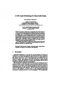
1 Introduction Electronic technology has been evolving very quickly during the last decades. Several million transistors can be integrated into a single VLSI chip, and today’s computer systems allow the production of millions of lines of code sized projects. In this scenario, the development difficulty has been pushed towards managing the problem complexity. Monolithic systems running on a single platform cannot usually solve real problems: software systems do not usually satisfy very tight non-functional requirements (performance, weight, cost . . . ), whereas hardware systems require longer development times and are less configurable. Intermediate solutions (programmable hardware such FPGAs, or software running on specific processors like DSPs) can sometimes fill in the gap. However, in most real systems mixed solutions must be adopted, leading to what has been called heterogeneous systems. In these systems, each subsystem is implemented in a different way (see figure 1), imposing most of the times different specification styles and the use of different design methodologies. Compiled Code and Virtual Machine Code allow a straightforward mapping with the UML. � This work has been funded by the Spanish Research Foundation (CICYT) through the project HADA TIC97-0928
Figure 1. Abstraction vs. Complexity in Heterogeneous Systems Development
Digital Signal Processors offer good results for some computation intensive problems. To implement Specific Hardware multiple solutions can be found in terms of technology (TTL, CMOS, ECL . . . ), component implementation (ASIC, FPGA, CPLD, FPLD . . . ) or subsystem implementation (MCM, PCB, SOC), with a variety of design methodologies and tools. A number of heterogeneous methods can be found also in prototyping. A different model of computation is often needed [2]. Developers prefer either frameworks or languages that help the analyst to concentrate on the problem domain (Matlab, Mathematica . . . ), or user-interface centered languages (ActiveX, Tcl/Tk, Visual Basic, Business Objects . . . ). Complex system designers cannot usually afford the use of this heterogeneous bunch of methods and tools, and the use of a common formalism that can manage the design complexity throughout the whole design process becomes essential.
This paper proposes the use of the Unified Modeling Language (UML), a standard in Object Oriented Analysis and Design, as support of a methodology that can successfully manage the inherent complexity of heterogeneous system design. The paper is structured as follows. Section 2 is devoted to briefly review some related previous work on heterogeneous systems design methodologies. In section 3, an overview of the UML is done. Taking the MPEG-4 decoder as example, the phases of the heterogeneous systems development process are depicted in section 4, making special emphasis on the main advantages of using the proposed methodology. Finally, some conclusions are drawn.
2 Related Work Object Oriented (OO) methodology is being successfully used by software developers and is now trying to be introduced in the hardware arena. Objective VHDL [8] (and some others [3, 4]) brings hardware design to the OO world (or vice versa). C++ [4] or Java [3, 11] can be used in almost all implementation technologies, if their standard syntax is improved and refined to accommodate hardware issues such as timing, communication or parallelism. However, choosing a unique language is a somewhat artificial solution for heterogeneity. It is probably arbitrary to state that C++ or Java are more suitable than VHDL for hardware design. Frameworks like Ptolemy [2] are more useful since each subsystem may keep its own implementation language, but aggregation of heterogeneous blocks does not lead to a consistent, homogeneous design. Reusable Intelectual Property (IP) Blocks [7] are a good solution. However, they just (greatly) simplify the implementation phases; an homogeneous language for the whole system is still needed. A sensible solution for a global system design is using the natural language (English), but this leads to an ambiguous and inconsistent design.
3 The Unified Modeling Language OO methods focus on modeling the vocabulary of the problem and the solution space in such a way that the real needs of project users can be accurately captured. They are suitable for unstable requirements since the OO development process is mainly iterative. Widely spread in software development, OO techniques are now being adopted as good engineering practices in non-software systems like business modeling and hardware design. The Unified Modeling Language [1] (UML) is a nonproprietary OO language for specifying, visualizing, constructing and documenting software systems. It allows the
modeling of concurrent, distributed systems and has welldefined extension mechanisms. Although the UML is broadly applicable without extensions, a small refinement is needed in order to model all the possible implementations in heterogeneous systems. The UML has three formal extension mechanisms called Stereotypes, Tagged Values and Constraints, that result especially suitable to our problem and will be introduced conveniently in following sections. In [1], an anchitecture-centric, use case-driven developpment process, called “The Rational Unified Process” is defined. This process is composed of several development cycles. Each development cycle consists of four phases: Inception, elaboration, construction and transition. Each phase is performed along many iteration steps.
4 A UML-based methodology In this section, the four phases of the Rational Unified Process are followed in detail for its use in heterogeneous system design. The discussions are illustrated with our case study, the MPEG-4 [6] (ISO/IEC 14496) decoder, the standard for multimedia communications.
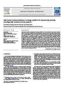
4.1 Inception In this phase, core requirements are established, so this is a very creative activity, where rules must not be very rigid. A use-case diagram shows the relationships between actors –things that interact with the system– and other usecases –patterns of behavior the system exhibits– in the system. Relationships show interactions between actors and use-cases. Defining the whole system using just one use-case is usually confusing. Diagrams may be hierarchical using UML packages, which have relationships between them. In our example, the MPEG-4 decoder can be decomposed into a video decoder and an audio decoder; each of one can decode natural or synthetic elements. The package labeled “main”, depicted in figure 2, shows the boundaries of the subsystem: the user in one side, which can interact with it, and the audiovisual stream in the other side that serves as input. Several Tagged-Values must be used in order to specify non-functional requirements that are known to be critical (see table 1).
4.2 Elaboration By means of the elaboration phase, we try to provide a complete, consistent, readable and revisable description of the system.
Application
{Performance}
{Performance}
Presenter capabilities
speed
iteration interval time
startTime stopTime
Multiplexing AVO Information
Downloading
File
isActive
Executive
paint()
Object
resize()
loop()
stop()
register()
Flexibility
Composition of AVOs
{Memory}
Stream
MediaObject
Object based Bitstream Manipulation and Edition
User {Portability} Compatibility
Content Management & protection and identificacion
Media interworking
Robustness to information errors/loss
Figure 2. “Main” use-case
AVScene worldinfo
URL
viewPoint
lock() unlock()
fog background
findNode()
clock
VisualRenderer capabilities paint() resize() select()
Reference
User interaction
{Performance, Portability}
id
Node bBox
AudioObject nChannel
AudioRenderer port bitsPerSample nChannels SamplesPerSecond
Bindable bindTime
ViewPoint orientation
Route
position
Tagged-Values MM class name Type UseCase Area Bool UseCasePerformanceBool UseCase Size Bool UseCase Security Bool UseCaseReliabilityBool UseCasePortabilityBool UseCase Memory Bool Class TargetImpl Enum
Stereotypes MM class name Class ASICEntity Class FPGAEntity Class CPLDEntity Class FPLDEntity Component ASICComp Component DSPComp Component FPGAComp Component FPLDComp Component CPLDComp
Table 1. Added extensions
{Paint.executionTime < 15 ms}
:Executive
:Presenter
Paint
:AudioRenderer
:VisualRenderer
:Node
paint lockScene getScene Node ref
render draw
stop
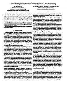
Figure 3. Sequence diagram
Figure 4. Class diagram A sequence diagram displays object interactions arranged in a time sequence, as shown in figure 3. In real time applications [10] these diagrams must be completed with the maximum allowed times between messages. In the rendering process of the MPEG-4 decoder (see figure 3), the rendering time is upper-bounded to 15 ms [5]. Note that in heterogeneous systems special care must be taken with synchronization issues. In figure 3, filled solid arrowheads are procedure calls, while half stick arrowheads represent an asynchronous flow of control. Heterogeneous systems exhibit some particularities that make it necessary to extend the UML model. First of all, a tagged-value (see table 1) has to be added to every class, so as to be able to indicate its target implementation (Java, C++, Objective VHDL . . . ). On the other hand, stereotypes (see table 1) have been added for hardware entities: ASICEntity, FPGAEntity, CPLDEntity, FPLDEntity. For our example, the MPEG-4 decoder, the audiovisual objects (AVO) hierarchy is partially depicted on the left of figure 4. Each AVO knows how to render itself, but two objects must control the rendering process: the VisualRenderer and the AudioRenderer. The Executive is a design object that creates the Presenter and the audiovisual scene (AVScene). To specify the life history of a given class, a state transition diagram is used. It shows the events that cause a transition from one state to another, and the actions that result from a state change. This diagram is derived from Harel’s statecharts and is very closed to synchronous languages like Argos. State-
Chart diagrams are especially useful to describe the behavior of ASICEntities since the control flow graph and the data path can be easily generated using automated tools.
4.3 Construction This phase is mainly iterative. Code is usually added and seldom removed. Unless important efforts are done to avoid it (using iterative design), system complexity will be always increasing. Component diagrams provide the modeling constructs needed to visualize the physical nature of your system. Source code components show compilation dependencies between language specific files (.java, .C, .H, .ovhd . . . ). Run time components show the mapping of classes to run-time libraries such as Java applets, dynamic libraries, VHDL libraries . . . Executable components show the interfaces and calling dependencies among executables. 4.3.1 Software construction Software components can be easily generated using UML CASE tools like Rational Rose [9]. With Rational Rose 98, developers can represent the architecture and automatically generate the application code and the documentation. Class libraries can be reverse-engineered into a Rose model file, leading to up-to-date models. 4.3.2 Hardware construction For hardware components, VHDL has been chosen as target code. However, VHDL is still far away from the UML. The encapsulation mechanisms of VHDL (entities) support just structural information reuse. An OO VHDL extension, Objective VHDL [8], has been used in order to allow a smooth transition from design to hardware implementation. It has been really helpful since it integrates class concept, (single) inheritance and polymorphism into VHDL. Objective VHDL has been easily embedded into the UML methodology. Rose98 has been extended for this purpose. Reverse engineering is also possible.
5 Conclusions In complex heterogeneous systems, the use of a common formalism that can manage the design complexity throughout the whole design process becomes essential. In this paper a design methodology based on the UML, a design
language supported by OMG (Object Management Group), has been proposed. Its suitability has been demonstrated by following all the design phases for a case study, an MPEG-4 decoder. The whole methodology has proven to be easily extendible and adequate for any implementation technology. At construction-time, the use of the UML assures elaboration-construction coherence in an iterative design. With this methodology (and its support tools) the first release of a design implementation can be automatically generated, and after further code modifications, the design model can be updated by reverse engineering.
References [1] G. Booch, J. Rumbaugh, and I. Jacobson. The Unified Modeling Language User Guide. Addison Wesley, 1998. [2] B. L. Evans, A. Kamas, and E. A. Lee. Design and simulation of heterogeneous systems using Ptolemy. In Rapid Prototyping of Application Specific Signal Processors (RASSP) Program, 1998. [3] R. Helaihel and K. Olukotun. Java as a specificaton language for hardware-software systems. In Proceedings of the International Conference on Computer-Aided Design, Nov 1997. [4] IMEC, IMEC vzw, Kapeldreef 75, B-3001 Leuven. The OCAPI Design System. [5] MPEG-4 Requirements, version 7 (Tokyo revision), March 1998. [6] Overview of the MPEG-4 Version 1 Standard. Tokyo, March 1998. Available on the WWW from URL http://www.mpeg.org. [7] G. Martin. Design methodologies for system level IP. In Proceedings of the Design Automation and Test in Europe, Paris, February 1998. [8] W. Putzke-R¨oming, M. Radetzki, and W. Nebel. Final Objective VHDL Language Definition. Available on the WWW from URL http://eis.informatik.unioldenburg.de/research/research.html, 1997. [9] Rational Software Corporation. Inside the UML. CD-ROM available on the WWW from URL http://www.rational.com/uml. [10] Rational Software Corporation. Unified Modeling Language for Real-Time Systems Design, 1997. Available on the WWW from URL http://www.rational.com/uml. [11] J. S. Young, J. MacDonald, M. Shilman, A. Tabbara, P. Hilfinger, and A. R. Newton. Design and specification of embedded systems in Java using successive, formal refinement. In Proceedings of the Design Automation Conference, 1998.