in C++, run as user-level processes on Windows NT workstations and export a ..... to start a Windows GUI application (the pipeline stage) on Windows NT 4.0.
IFIP/ACM Middleware 2000
Hierarchical Architecture for Real-Time Adaptive Resource Management Ionut Cardei1, Rakesh Jha2, Mihaela Cardei1, Allalaghatta Pavan2 Honeywell Technology Center 3660 Technology Drive, Minneapolis, MN 55418, USA 1 {ionut, mihaela}@cs.umn.edu, 2{jha, pavan}@htc.honeywell.com
Abstract. This paper presents the Real Time Adaptive Resource Management system (RTARM1), developed at the Honeywell Technology Center. RTARM supports provision of integrated services for real-time distributed applications and offers management services for end-to-end QoS negotiation, QoS adaptation, real-time monitoring and hierarchical QoS feedback adaptation. In this paper, we focus on the hierarchical architecture of RTARM, its flexibility, internal mechanisms and protocols that enable management of resources for integrated services. The architecture extensibility is emphasized with the description of several service managers, including an object wrapper build around the NetEx real-time network resource management. We use practical experiments with a distributed Automatic Target Recognition application and a synthetic pipeline application to illustrate the impact of RTARM on the application behavior and to evaluate the system performance.
1 Introduction Current distributed mission-critical environments employ heterogeneous resources that are shared by a host of diverse applications cooperating towards a common mission goal. These applications are generally a mix of hard-, soft- and non-real-time applications with different levels of criticality and have a variety of structures, ranging from periodic independent tasks, multimedia streams and parallel pipelines, to event-driven method-invocation communicating components. The applications usually tolerate a range of Quality of Services (QoS) and are ready to trade off QoS in favor of the most critical functions they perform. The distributed systems must be able to evolve and adapt to the high variability in resource demands and criticality of the applications as well as to the changing availability of resources. The current industry trend is to build distributed environments for mission-critical applications using “Common-Off-The-Shelf” (COTS) commercial hardware and software components. A middleware layer above the COTS components provides consistent management for the system resources, decreases complexity and development costs.
1
Funded by DARPA under NRaD Contract number N66001-97-C-8524.
J. Sventek and G. Coulson (Eds.): Middleware 2000, LNCS 1795, pp. 415-434, 2000. © Springer-Verlag Berlin Heidelberg 2000
415
416 IFIP/ACM Middleware 2000 This paper presents the Real Time Adaptive Resource Management system (RTARM), developed at the Honeywell Technology Center, that implements a general middleware architecture/framework for adaptive management for integrated services aimed to real-time mission-critical distributed applications. The RTARM system has the following basic features [5]: (1) scalable end-to-end criticality-based QoS contract negotiation that allows distributed applications to share common resources while maximizing their utilization and execution quality; (2) endto-end QoS adaptation that dynamically adjusts application resource utilization according to their availability while optimizing application QoS; (3) integrated services for CPU and network resources with end-to-end QoS guarantees; (4) realtime application QoS monitoring for integrated services and (5) plug-and-play architecture components for easy extensibility for new services. The resource management architecture for RTARM uses an innovative approach that unifies heterogeneous resources and their management functions into a hierarchical uniform abstract service model [5]. The building block of the architecture is the Service Manager (SM). It encapsulates a set of services and their management functions and exports a common interface to clients and other service managers. This facilitates recursive hierarchies, in which heterogeneous services are integrated bottom-up. A higher-level service manager aggregates services provided by itself and its lower-level SMs and provides clients with a higher-level QoS representation. In this paper, we focus on the architecture, protocols and implementation of an RTARM prototype that supports integrated services for real-time distributed applications. It runs as a middleware on a network of workstations and uses CORBA for portable communication. A major contribution of our work is the hierarchical feedback adaptation mechanism [1] that provides efficient dynamic QoS control for distributed data-flow applications. We illustrate the RTARM capabilities with a practical experiment with an Automatic Target Recognition (ATR) distributed application [9] and with a synthetic pipeline demonstration application. The DARPA Quorum program [11] provides an extensive framework for QoSrelated research projects. Similar efforts for building adaptive management systems for heterogeneous resources are GRMS [6,7], ARA [9,12], and QualMan [10]. GRMS is a precursor of RTARM. It introduced the uniform resource model and the atomic ripple scheduling protocol. Its hierarchical architecture reflects the application data flow and does not offer feedback adaptation. ARA considers a discrete set of runtime configurations for distributed applications and does feedback adaptation by resource reallocation. The ARA architecture is non-recursive and differs considerably from the uniform RTARM architecture by using proxies for specific service providers. QualMan is designed for multimedia applications and defines two basic resource management components, the resource scheduler and the QoS broker, that adhere to a uniform resource model without considering deeper recursive structures and QoS composition. [2] introduces a portable and QoS-enabled middleware platform suitable for building multimedia and real-time distributed applications. The rest of this paper is organized as follows. Section 2 describes the RTARM hierarchical architecture, system models and interfaces. Section 3 presents the architecture of a Service Manager and describes the CPU, network and a higher-level SM. Section 4 continues with experiments involving an ATR application and
416
IFIP/ACM Middleware 2000
417
synthetic pipeline applications that emphasize the RTARM capabilities. The paper concludes in Section 5 with a discussion and future plans.
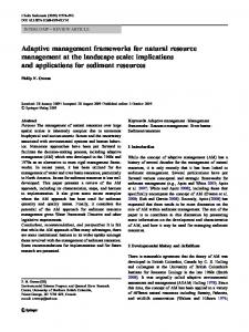
2 The RTARM System Architecture We have designed and implemented the RTARM system prototype as a middleware layer above the operating system and network resources. The middleware approach provides the benefit of flexibility and portability but the increased distance to the basic resources makes fine-grained control difficult. The RTARM servers, developed in C++, run as user-level processes on Windows NT workstations and export a CORBA (Orbix [8]) interface to clients and applications. The RTARM model differentiates between clients and applications. A client is any entity that issues a request for services and negotiates a QoS contract that defines the allocated services. An application consumes services reserved by a client on its behalf and continuously cooperates with the resource management system to achieve the best available QoS while maintaining its runtime parameters within the contracted region. The QoS contract may change during the application lifetime. 2.1 The Service Manager Hierarchy The RTARM system employs a hierarchical resource management architecture that facilitates provision of integrated services over heterogeneous resources. The uniform resource model [5] defines a recursive structural entity called Service Manager (SM) that encapsulates a set of resources and their management mechanism. At the bottom of the hierarchy are SMs that provide management functions for basic resources, such as CPU or network resources, and directly control resource utilization by application components. Higher level services are assembled on top of lower-level services, giving rise to a service hierarchy.
Clients SM 1
Integrated Service HSM2
Network SM
CPU SM
APP1
APP2
Fig. 1. Sample RTARM hierarchy consisting of one network SM, one CPU SM and two integrated service managers
417
418 IFIP/ACM Middleware 2000 Resources as well as negotiation requests are treated uniformly across the entire hierarchy. Higher-level service managers (HSM) may act as clients for lower-level SMs (LSM). The hierarchy allows dynamic configuration as new service managers can join the system at any time. A request for an integrated service sent to an HSM may require resources from lower-level service providers. The admission protocol builds a virtual reservation tree over the SM hierarchy that remains valid for the entire application lifetime. The SM hierarchy forms a directed acyclic graph, with SM as nodes and edges represented by the “uses-services-from” relation. Figure 1 illustrates a simple RTARM hierarchy with two LSMs, a CPU and a Network SM, at the bottom of the hierarchy. Two clients request services from the two HSMs while applications are consuming CPU and network resources. Section 3 describes the service managers in more detail. There are several benefits from a hierarchical, recursive, resource management architecture. First, services with complex, composite QoS representations are easier to implement on top of basic services. Complex distributed applications benefit from a richer representation of QoS. It simplifies the application design and facilitates consistent resource management for QoS-incompatible applications. Regardless of how complex the application architecture and QoS semantics are at the top of the SM hierarchy, at the bottom of the hierarchy everything translates to QoS requests for basic services (CPU and network in our prototype). The hierarchical architecture of RTARM scales well with large distributed environments. Many SMs grouped in clusters may benefit from service localization and avoid communication bottlenecks. Sharing of LSMs between HSMs adds redundancy, fault tolerance and load balancing. In contrast, the centralized approach for heterogeneous resource management in distributed environments may introduce the drawbacks of a central controller: communication and processing bottleneck, one point of failure and decreased flexibility, but has certain performance benefits and lower latency. A potential shortcoming for deep RTARM hierarchies derives from the increased distance between the top-most-level SM and bottom layer in the hierarchy. This may cause high latency for time sensitive RTARM functions, such as feedback adaptation and application control in case of deep SM hierarchies. Issues related to deadlock prevention and distributed SM synchronization have been studied for the GRMS project [6,7] and can be easily extended to the RTARM model. 2.2 RTARM System Models 2.2.1 QoS Model and Translation. The quality of the interaction of a mission-critical application with a dynamic environment directly reflects its performance. The wide magnitude of this interaction requires a range for the quality measures. RTARM supports a multidimensional QoS representation, each dimension specifying an acceptable range [Qmin, Qmax] of a quality parameter for the application. A set of range specifications, one per dimension, defines a QoS region. This QoS model facilitates resource negotiation and makes resource management more flexible.
418
IFIP/ACM Middleware 2000
419
In the RTARM recursive hierarchy, the QoS representation at a SM reflects the type of services provided by that SM. An HSM translates a QoS request for integrated services into individual QoS requests for services provided by itself and its lowerlevel SMs. When the SM receives replies from its LSMs, it reassembles the returned QoS into its own QoS representation in a process called QoS reverse-translation. RTARM uses a unique implementation for QoS, which is independent of the addressed service. We define a QoS parameter as a set of name-value pairs, where the value part is a sequence of one or more scalar primitive data values (string, short, double, etc.) and the name indicates the specific QoS dimension, such as “rate”, “workload”, “latency”, etc.. 2.2.2 Adaptation Model. RTARM recognizes three situations when application QoS may be changed after admission [5]: (1a) QoS shrinking/reduction of lower criticality applications when a new application comes; (1b) QoS expansion/improvement when applications depart and release resources, and (2) feedback adaptation. While (1a) and (1b) imply contract changes and involve other applications, feedback adaptation does not change the contract but only varies the current operational point of the application within the contracted QoS region. Feedback adaptation is like closed loop control. It relies on monitoring of delivered QoS and uses the difference between delivered and desired QoS to adapt the application behavior. 2.3 RTARM Interfaces Each SM implements and exports three interfaces: (1) Negotiator for admission control, collateral adaptation, QoS expansion and application control, such as suspend, resume and end; (2) Service Manager for SM hierarchy set up (register/deregister SM) and (3) Monitor for application monitoring and event propagation. For admission control and adaptation RTARM uses a modified version of the GRMS Ripple Scheduling algorithm [6,7]. A detailed description with examples follows in Section 3.4. Briefly said, RTARM admission and adaptation employ a transaction-based two-phase commit protocol applied recursively at each SM. The first phase executes a service availability test starting from the SM that received the admission request, down on the reservation tree that resulted from the QoS translation and request dispatch process. The available, reserved QoS propagates back to the initiator SM from the lowest SM layer, being reverse-translated along the way. In the second phase, the initiator SM assesses the success status of the reservation phase and the transaction is committed or aborted, implying service reservations along the spanning tree to be committed, or to be cancelled, respectively. If not enough resources are available, a SM will try to adapt lower criticality applications to their minimum contracted QoS and use the released resources for the new application. Later, when resources become available, the SM expands the QoS for the most critical applications. Sometimes in order to admit a new, more critical application, it is enough to squeeze the QoS of only a part of an existing distributed application. Then, changes in the high-level QoS may require collateral adaptation of other components of the
419
420 IFIP/ACM Middleware 2000 application that do not directly impact admission of the new application. For instance, for a multimedia stream application having frame rate as QoS parameter, if one processing stage is adapted to the minimum rate, than all other stages will run at the same low rate, too. The next section presents the object architecture of the SM and details the implementation of a CPU, a Network and a Higher-level SM.
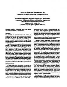
3 RTARM Service Managers 3.1 The Service Manager Architecture and Implementation The unified resource model provides the benefits of a uniform internal architecture for all service managers (Figure 2) and a common interface between them.
Involved in Admission Control and CrossApplication Adaptation
Translator
Shared Data Structures: SMs, Application Contracts, FB-Adaptation and Monitoring
Negotiator
FB-Adapter
Allocator Scheduler
Detector
Adapter Configuration Manager
Monitor
Enactor Involved In Feedback Adaptation Only
Fig. 2. The internal object architecture of a service manager
The arrows in the figure indicate object service requests. The components in a SM are as follows: • Negotiator: brokers contract admission, delegates responsibilities to other components and exports the external RTARM CORBA interface. • Translator: translates higher-layer integrated QoS into lower-layer QoS representation. • Allocator: handles resource allocation/release when no adaptation is necessary. • Adapter: handles resource allocation/release with adaptation and QoS expansion/contraction. • Scheduler: determines whether allocation of resources and expansion of application QoS are feasible. • Enactor: enforces changes in application QoS or status.
420
IFIP/ACM Middleware 2000
421
• Monitor: keeps an eye on applications in execution and passes status information and QoS usage to the Detector. Exports external RTARM CORBA interface. • Detector: uses application runtime information (e.g. current QoS operational point) to detect significant changes in application operation (e.g. overload, underutilization, contract violation). Triggers Feedback Adapter actions. • Feedback Adapter: decides corrective actions for applications when their runtime status changes significantly. Additional data structures exist to hold information regarding application contracts, other service managers and available services. Applications implement a simple CORBA interface that allows SMs to change their QoS and status. LSMs keep proxies for the application CORBA server objects. All RTARM CORBA servers and applications are started in the shared, multi-client activation mode. A SM component class has the same object interface regardless of the SM position in the hierarchy or the resources the SM controls. For instance, the Adapter object implements the same functions in all SMs, but in a way that depends actually on the scope of the SM. Not all components are required within a SM. For example, a Translator may exist only inside an HSM. RTARM provides a common object oriented execution framework that allows users to dynamically load SM components from shared libraries during runtime configuration. A configuration manager uses a mechanism similar to a Factory Method [4] to instantiate SM components. It also passes configuration information extracted from a configuration file to the SM components during their initialization. For all SMs there is a single executable program that originally contains the empty SM framework and the configuration manager. By loading specialized components from shared libraries, the configuration manager practically starts different SMs. We use this technique when we initialize the CPU, Network and Higher-level SMs with components from specific Windows NT DLLs. The flexibility of this plug-and-play feature permits implementation of a new SM by just replacing a set of components that realize a particular SM component interface, without rewriting the whole program. Writing a new SM component only requires the header file with the object interface, the executable program (common execution framework) and its corresponding library.
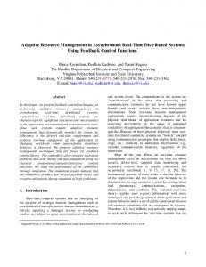
3.2 The CPU Service Manager The CPU SM provides periodic applications access to a processor resource. Each computing node has a CPU SM, allowing concurrent applications to share a CPU. The application QoS is bi-dimensional: application execution rate (R) and iteration execution time (W) (Figure 3). The COP (Current Operational Point) represents the current values for the multidimensional QoS.
421
422 IFIP/ACM Middleware 2000
Rate
RxW=%CPU utilization=constant
Requested region
Feasible region
C.O.P
Workload Fig. 3. CPU Service Manager QoS representation
3.2.1 Admission and Adaptation. The specific CPU scheduling policy is isolated within the Scheduler object and the Monitor keeps track of application CPU utilization. The invariant condition for admission and schedulability for n applications is Σi=1..nRiWi < 100% processor utilization. A more sophisticated CPU SM can be implemented at any time, by just using the plug-and-play feature, replacing the default Scheduler component with one specific to the scheduling discipline used. The CPU SM service allocation unit for each periodic application is the fraction of CPU utilization (R x W). The CPU SM communicates this information to applications and assumes they are well behaved and keep their process utilization below the allocated limits. The SM scheduler only assigns application rates and does not control the underlying OS scheduler. This policy works fine on a larger time scale and for our experimental purposes. For real-time performance one solution is to implement a soft real-time CPU scheduling server above the OS scheduler [10]. Commercial operating systems with soft real-time capabilities, like Windows NT and Solaris, limit the scheduler granularity to 10-20ms. The CPU SM implements the Ripple Scheduling admission protocol. Because it is at the bottom of the SM hierarchy and has no LSMs, it does not make any other recursive calls. Adaptation and collateral adaptation reduce the application rate to the minimum contracted value. QoS expansion increases the application contracted QoS (rate) to the best available value. 3.2.2 Feedback Adaptation. The CPU SM controls the task rate in real-time. It cannot change the workload, which is left exclusively under application control. Applications send their current QoS operational point as events to the CPU SM monitor at the end of each periodic iteration. At any moment, the QoS COP may vary so that R x W ≤ L, where L is the fraction of the contracted processor utilization. The CPU SM adjusts the COP as follows: (1) increase rate when workload decreases; (2) decrease rate on overload, when the workload pushes the COP outside the contracted region.
422
IFIP/ACM Middleware 2000
423
3.3 The Network Service Manager We integrated the NetEx real-time network management system [3,13] from Texas A&M University into the RTARM system. NetEx runs as middleware and provides connection-oriented real-time communication with guaranteed delay and bandwidth over COTS network infrastructure, such as ATM and switched 10/100 Mbps Ethernet. NetEx uses a tri-dimensional QoS: period, delay and message size and adds the connection source and destination network addresses to the connection contract. The NetEx resource management interface is, however, incompatible with the RTARM interfaces. It has different semantics and it does not export the two-phase commit protocol. We built an object-oriented wrapper [4] around NetEx that hides the incompatibilities and exports the RTARM interface to clients, applications and HSMs (Figure 4). The wrapper method can be used to integrate any service provider in the RTARM architecture.
HSM NetEx Object Wrapper
Negotiator Adapter
NetEx Library
Allocator
Enactor
Application
Scheduler
Fig. 4. The object wrapper for NetEx communication manager
The wrapper implements three SM components, Negotiator, Adapter and Enactor, that map the RTARM interface calls for admission, adaptation and expansion to the native NetEx API. NetEx does not provide feedback adaptation for connections, so the wrapper SM does not implement feedback adaptation either. It is important to note, however, that our HSM for integrated services for parallel pipeline applications implements hierarchical feedback adaptation. This is detailed in the next section. 3.4 The Higher-Level Service Manager for Integrated Services Within the RTARM service manager hierarchy, HSMs aggregate services from LSMs (CPU, Network or any other type of SM) and provide RTARM services to
423
424 IFIP/ACM Middleware 2000 applications that need a more complex QoS representation. The unified resource model enables recursive deployment of HSMs. Our HSM implementation is generic and is able to support various types of distributed applications with arbitrary QoS representations that map to available LSM QoS. The only restriction is that the Ripple Scheduling admission and adaptation procedure and the hierarchical feedback adaptation must not contradict the application semantics. The QoS Translator SM component inside an HSM is responsible for translating a QoS request into something the LSMs understand. Replacing the translator component with a different one (for a different QoS representation) produces a HSM capable of supporting different integrated services. 3.4.1 Admission and Adaptation. The Negotiator implements the recursive twophase admission protocol that runs at the heart of each HSM. The code for the first phase, reservation, follows next: test_reservation(in reqQos, out avQos, in candidates, out adaptedApps) // reqQoS is the requested QoS region // avQoS is the returned (acceptable) QoS region // candidates is the list of applications that may be // adapted in order to accommodate the current request // adaptedApps is the list of adapted applications { translate reqQos into: LS – list of requested services from LSMs, and LreqQos – corresponding QoS per service. for each service S from LS { for each LSM lsm that provides service S { success = lsm->test_reservation(LreqQoS[lsm], lsmAvQos[S], candidates that run on lsm, lsmAdaptedApps[S]) if success then mark admitted service and continue with next service S from LS } if service S was not admitted then { cancel all previous successful reservations return false } } // now all services from LS have been admitted reverse-translate and maximize the returned QoS from lsmAvQos into avQoS perform collateral adaptation if necessary return true }
The second phase that commits the resource reservation from phase I is implemented like this:
424
IFIP/ACM Middleware 2000
425
commit_reservation(in committedQos, in adaptedApps) // commitedQos is the QoS region to commit // adaptedApps is a list of applications (adapted in phase // I) whose adaptations have to be committed { translate commitedQos into: Llsm – list of LSMs and LcommittedQos – committed QoS per service for each lsm from Llsm { lsm->commit_reservation(LcommitedQos[lsm], adaptedApps that run on lsm) } save committedQos into the application contract }
The cancel_reservation() call is similar to commit_reservation() and is omitted here. Figures 5 and 6 illustrate examples of admission of a new application with id 3 at an HSM H that has 3 LSMs, L1, L2, L3.
1-test_reservation(3)
RTARM calls: 1,2,3 – test_reservation 4,5 – test_adapt 6,7,8 – commit_reservation 9 – commit_adapt 1.1 2.1 3.1
L1
1, 2 2
6-commit_reservation(3)
H 5
3 4 8
7 1.2 3.2
9
L2
1.3 2.2
L3
Fig. 5. Example of successful admission of application 3 at the HSM “H”
Applications 1 and 2 are already running at H and use services from L1, L2, L3. For example, application 1 (denoted with 1 at H) runs also at L1 (1.1), at L2 (1.2) and L3 (denoted 1.3). The new application 3 requires two services and maps to 3.1 and 3.2. In example a) both 3.1 and 3.2 are admitted at L1 and L2. Admission for 3.1 needs adaptation of application 1.1 on L1. This triggers collateral adaptations for 1.2 as well as 1.3, as the entire application 1 must be adapted. Calls 4 and 5 (test_adapt) ask L2 and L3 to adapt collaterally application 1. During the execution of commit_reservation on H (call number 6), the collateral adaptation of 1 is committed on L1 and L2 with the two commit_reservation calls plus the extra commit_adapt call (9) to L3. The example from Figure 6 shows the call sequence when application 3 is accepted by L1, but rejected both by L2 and L3. HSM H finally rejects 3 and returns false to the test_reservation call 1.
425
426 IFIP/ACM Middleware 2000
1-test_reservation(3) 1, 2
RTARM calls: 1,2,3,4 – test_reservation 5 – cancel_reservation 1.1 2.1 3.1
2
4
3
5
L1
H
1.2
L2
1.3 2.2
L3
3.2 not admitted
Fig. 6. Example of failed admission of application 3 at the HSM “H”. Stage 3.2 is denied by both L1 and L2
We have implemented a Pipeline Service Manager (PSM), an HSM that aggregates services from lower-level SMs (CPU, Network, other HSMs) into a higher-level integrated representation suited for pipeline applications. Our PSM supports periodic independent tasks and periodic parallel pipeline applications, consisting of communicating stages in an arbitrary configuration, with a single source and a single sink node. We assume a sensor enters periodically data frames in the pipeline. Each frame is processed by a stage or a composite stage [1] (consisting of parallel strings of elementary stages) and then sent to the next stage. Such a pipeline application is depicted in Figure 7.
1 3
0
4
5
6
2
Fig. 7. Sample parallel pipeline application with 7 stages
For periodic pipeline applications, we use a QoS consisting of end-to-end message latency and rate for the final stage. The admission contract also contains execution time for each stage as well as the message size for each inter-stage connection. It is the job of the pipeline translator to decompose the integrated-service pipeline request into CPU and network admission requests. We assume all stages use the same range for rate. The pipeline QoS (end-to-end latency, frame rate plus state workloads and message sizes) translates into CPU QoS parameters for all stages and Network QoS for all network connections. The CPU QoS rate range is the same as that for the pipeline frame rate. The pipeline translator uses the same rate range and a fraction of the end-to-end pipeline latency to generate the Network QoS parameters.
426
IFIP/ACM Middleware 2000
427
3.4.2 Hierarchical Feedback Adaptation for Parallel Data-Flow Applications. We have implemented an innovative and efficient hierarchical feedback adaptation mechanism for parallel pipeline applications [1]. It performs feedback adaptation at two levels in the SM hierarchy. The pipeline end-to-end latency is controlled at the HSM level while the CPU SMs perform CPU feedback adaptation independent of the HSM. The pipeline QoS parameter we consider critical and want to control is the end-toend latency. As the pipeline evolves in time, rates of intermediate stages may change as a result of CPU SM feedback adaptation. In normal circumstances, the input sensor period is maintained at a value greater than the current period of any stage/substage of the parallel pipeline application, but it can get lower because of independent CPU feedback adaptation. When accumulation of queues between stages increases the endto-end latency beyond a maximum threshold, the PSM sets the input sensor period at the maximum value from the pipeline contract. A finite state machine in the PSM maintains this maximal period for a fixed time, allowing the queues to empty. Then, the PSM sets again the input sensor period to the maximal current period of all stages, typically lower than maximum period from the contract. We have proved in [1] that the end-to-end latency decreases, and that after a finite number of frames the pipeline enters a region of stability where the end-to-end latency and the output frame rate are within the contracted region. This method is simple and quite efficient, as the only parameter to be adjusted is the sensor input period, while the pipeline stages are controlled only by the corresponding CPU SM. This mechanism avoids costly communication and coordination between the HSM and all the CPU SMs. The information required for pipeline feedback adaptation is minimal: the end-to-end latency for the current frame and the maximal current period of all stages. In the next section we present experiments with synthetic pipeline applications and an Automatic Target Recognition application and we give performance estimates for the RTARM system.
4 Experiments and Performance Evaluations In this section we present two preliminary experiments that reflect our current research progress. We need further work to fully assess the implication of the hierarchical architecture to the overall system performance. The first experiment deals with synthetic pipeline applications and yields performance numbers for admission, adaptation and QoS expansion for the CPU, Network and Pipeline SMs. The second experiment tests feedback adaptation for parallel pipeline applications. The Forward Looking Infrared Automatic Target Recognition application provides an excellent testbed to prove the efficiency of our hierarchical feedback adaptation technique. The runtime environment for these experiments consists of three 450MHz Dell Workstation-400 machines, running Windows NT, connected via a Fore ATM switch with OC-3c (155Mbps) links. Each machine hosts a CPU SM. Both the network SM that controls the inter-stage communication and the pipeline SM run on one of the three machines. We consider their own CPU resource consumption negligible. All
427
428 IFIP/ACM Middleware 2000 inter-SM CORBA communication uses a secondary Fast Ethernet network, so the ATM lines remain 100% available for inter-stage communication. We used the NT performance counter for precise time measurements. 4.1 Performance for Admission and Adaptation For evaluating admission, adaptation and expansion performance for pipeline applications we devised two scenarios. Client
P C1
N
C2
1.1 1.2 1.3
Pipeline 1
2.1 2.2 2.3
Pipeline 2
Fig. 8. Scenario 1. SM configuration and stage mapping
Scenario 1. 1. We tested admission of three-stage pipelines on a SM hierarchy with one HSM (P), one NSM (N) and two CPU SMs (C1, C2), as illustrated in Figure 8. The sequence of events is: 2. admit pipeline 1; no adaptation required. 3. admit pipeline 2 with higher criticality; stage 1.1 is adapted due to CPU constraints on SM C1; stages 1.2, 1.3 and network connections are adapted collaterally. 4. terminate pipeline 2; pipeline 1 is expanded back to its original QoS (all stages and the network connections). 5. try admission for pipeline 3 with lower criticality than 1; not enough CPU resources, admission is denied. 6. terminate pipeline 1. Scenario 2 runs on the same environment as Scenario 1 and is similar, except the pipeline applications now have two stages and adaptation is caused only by network bandwidth constraints, not by CPU resource insufficiency. Throughout the tests we measured the time required to complete the RTARM interface calls for admission, adaptation and expansion for the CPU, Network and
428
IFIP/ACM Middleware 2000
429
Pipeline SM. The measured time consists of the actual processing overhead and time to complete nested calls to: (1) application CORBA servers for the CPU SM; (2) the NetEx management subsystem and application CORBA servers for the Network SM (NetEx wrapper) and (3) LSMs for the Pipeline SM. The performance measurements for the Pipeline SM are listed in Table 1, for the CPU SM in Table 2 and for the Network SM in Table 3. All values are expressed in milliseconds. Table 1. Performance measurements for the Pipeline Service Manager w/o Adaptation Total time Processing time* test_reservation commit_reservation cancel_reservation test_expansion commit_expansion end_app
99.159 2239.02 7.102
252.325
17.972 6.366 0.313
1.414
with Adaptation Total time Processing time 118.344 2376.34
18.899 11.338
212.751 39.987 460.348
4.508 4.921 4.145
Table 2. Performance measurements for the CPU Service Manager
test_reservation commit_reservation cancel_reservation test_adapt test_expansion commit_expansion end_app
w/o Adaptation with CORBA w/o CORBA 0.447 525.165 0.474 0.146
4.619
with Adaptation with CORBA w/o CORBA 0.707 544.796 1.397 0.168 0.234 0.189 3.132 0.112
0.846
Table 3. Performance measurements for the Network Service Manager
test_reservation commit_reservation test_adapt test_expansion commit_expansion end_app
Total time 22.475 45.434
10.08
w/o Adaptation Processing CORBA NETEX Total time time time time 3.147 0 19.328 48.414 0.637 44.797 0 49.962 0.056 33.093 0.697 0.289 0 9.791
with Adaptation Processing CORBA NETEX time time time 3.901 0 44.513 1.105 48.857 0 0.056 0 0 0.355 0 32.738 0.697 0 0
For the PSM the “Total Time” columns include the sequence of recursive RTARM CORBA calls to the LSMs and the algorithm processing overhead. Some calls may
429
430 IFIP/ACM Middleware 2000 require adaptation of lower criticality applications, such as test_reservation() at step 2 in scenario 1; other calls, like the expansion operations, are 100% with adaptation. From Table 1 we notice that the reservation operations and end_app() require extra processing work if adaptation is involved. Also the processing time for test_reservation() is considerably larger than all other calls since it involves back-and-forth QoS translation and reverse-translation. But what stands out is the large total time consumed for commit_reservation() for a three stage pipeline application, approximately 2.3 seconds. This time includes the duration for commit_reservation() calls to the CPU SM that take more than 500ms for each pipeline stage (see Table 2). A CPU commit_reservation() call actually generates a set_qos() call with the committed application QoS to the application stage CORBA server. The stages are not up and running when admission happens. The Orbix daemon [8] starts the stage process and passes the CORBA server IIOP TCP port number and IP address to the CPU SM. Only after the stage is up and initialized it is able to respond to the set_qos() CORBA call from the CPU SM. The time to start a Windows GUI application (the pipeline stage) on Windows NT 4.0 is around half a second for our test configuration. Table 3 shows time measurements for the Nework SM These are more complex since the NetEx wrapper communicates through TCP/IP with the NetEx Host Traffic Manager [3,13] and stages through set_qos() CORBA calls (only during commit_reservation()). The communication latency overhead caused by NetEx is comparable to CORBA communication overhead, between 10 and 45ms. We conclude that operation of the RTARM system is efficient, except the commit_reservation() call for CPU applications. This major delay can be completely avoided by pre-loading the applications before the client submits the pipeline contract to the HSM. The overall system performance may further improve by using a faster CORBA implementation that guarantees real-time operation deadlines. 4.2 Performance for Hierarchical Feedback Adaptation 4.2.1 The Automatic Target Recognition Experiment. We tested the RTARM feedback adaptation mechanism on a true mission-critical application. The ATR application, schematically shown in Figure 9, processes video frames captured by a camera and displays recognized targets on a display. Stage 0 (the sensor) generates frames that are passed through a series of filters and processing elements up to stage 6, which displays the original image and the identified targets. The frames are 8-bit, 360x360 pixels, monochrome images, and contain a variable number of targets (from 3 to 50), depending on the frame. Stages 4, 5 and 6 expose a variable workload, proportional to the number of targets, that without feedback adaptation would cause queue accumulations with negative effect on the end-to-end frame latency.
430
IFIP/ACM Middleware 2000
431
1 3
0
4
5
6
2
time
Frame Arrival Period
End-to-End Latency
Fig. 9. ATR pipeline application and its high-level QoS
4.2.2 Performance Metrics and Evaluation. The ATR pipeline contract requires an acceptable output frame period interval of [1,5] s, and a frame latency of 0.7-13 s. The seven ATR stages run at a variable workload between 0.02s and 1.5s and within the same period interval [1,5] s. We first present timing measurements for the feedback adaptation at the CPU SM and PSM SM level (Figure 10). We measured the processing overhead of the feedback adaptation code (part 2 in Figure 10) and the time it takes the SM to react from the moment it receives the current QoS from the application until its adaptation command is enforced (part 2 + part 3).
Pipeline SM
CPU SM 2 1
2 1
3
event(COP)
set_qos(newQoS)
3
event(COP)
Application
set_qos(newQoS)
CPU SM
... Fig. 10. Measuring feedback adaptation performance
The measured times are displayed in Table 4. For the CPU feedback adaptation, detection and enforcing the QoS adaptation takes around 4.4ms. Most of the time, 3.9ms, is spent in a set_qos() operation, a two-way normal, local CORBA call. The pipeline adaptation enforcement includes a set_qos() call to the CPU SM that controls the sensor (or first stage) that calls directly the first stage with a set_qos()call. This explains why enacting pipeline QoS adaptation takes almost double than for CPU SM QoS. Figure 11 displays CPU feedback adaptation for stage 4 in the ATR pipeline. The stage has variable workload that triggers its CPU SM to change its rate. Points A
431
432 IFIP/ACM Middleware 2000
Table 4. Feedback adaptation performance results for CPU SM and PSM
CPU SM
Detection and
Decision
Total Time
decision processing (2) 0.508 ms
Enactment (3) 3.914 ms
(2+3) 4.422 ms
0.859 ms
6.816 ms
7.675 ms
Pipeline SM
indicate overload that triggers rate decrease and points B indicate chronic underutilization that determines rate increase.
1.6 1.4 1.2 1
B
B
0.8 0.6 0.4
A A
0.2 0 100
110
120
130
140
150
160
170
180
190
200
Experiment time (seconds) W orkload
Rate
CPU Load=Rate x W orkload
Fig. 11. CPU SM feedback adaptation for a task with variable workload
While running the ATR application, the pipeline feedback adaptation mechanism makes sure the end-to-end latency and rate stay in the contracted range (Figure 12). In order to practically demonstrate its effectiveness, we disabled the pipeline feedback adaptation after some time while keeping the sensor input period at a sustained low value of 1.48s (0.67Hz). This caused accumulation of frames in stage queues that translated into an increasing end-to-end frame latency. While feedback adaptation was disabled we actually did not get latency measurements, so we drew a dotted line between points A and B. When the latency reached 30s, way above the contracted value, we re-enabled pipeline feedback adaptation. Immediately the PSM sensor increased the sensor input period up to 5s. The latency went rapidly down (B Å C), below the threshold, after a brief spike caused by the inertia of the more than 23 frames already in transit through the pipeline.
432
IFIP/ACM Middleware 2000
433
40 35 s 30 e c 25 o n 20 d s 15
Enable pipeline feedback adaptation at t=764s
End-to-end Latency
Disable pipeline feedback adaptation at t=460s
Threshold
10
C
5 0 350
Sensor Input Period
B
A 650 450 550 Elapsed Time (seconds)
750
850
Fig. 12. Latency variation for ATR with and without pipeline feedback adaptation
The feedback adaptation algorithm we implemented tends to keep the intermediary stage queues empty while changing the input sensor period only. This is effective but introduces high oscillations for latency. Further research will use control theory to design more efficient algorithms that use target history and prediction, able to smooth down the end-to-end latency oscillations without compromising overall performance and response time. Our hierarchical feedback adaptation algorithm proved to be effective and efficient. Detection, decision and enforcement take less than 8ms and involve only the CPU SMs for the sensor and the last stage that actually reports the latency and rate.
5 Conclusions This paper presents the middleware architecture and implementation of the RTARM system. We have first focused on the architectural elements that enable RTARM support for integrated services: (1) the uniform service management recursive hierarchy and protocols, (2) the common architecture of a Service Manager that facilitates rapid object-oriented prototyping, massive code reuse and features plugand-play support for SM components. Then we detailed the specific service managers that constitute the RTARM hierarchy. The clean and flexible architecture of a SM allowed us to integrate quickly a new service provider in the RTARM hierarchy. We built an object wrapper around the incompatible interface of the NetEx network management system that provided the same CORBA interface implemented by all RTARM service managers. Finally, we presented experiments that illustrate the practical use of the RTARM system and its effectiveness for a real-world Automatic Target Recognition
433
434 IFIP/ACM Middleware 2000 application. We demonstrated that our hierarchical feedback adaptation mechanism is able to efficiently control in real time the dynamic behavior of a parallel pipeline distributed application. We plan to port RTARM to a real-time CORBA implementation, such as WUStL TAO [14] and to optimize its performance. We also intend to develop more sophisticated feedback adaptation mechanisms with prediction features which would further decrease the system reaction time while optimizing the application QoS.
References 1. Cardei, M., Cardei, I., Jha, R., Pavan, A., “Hierarchical Feedback Adaptation For Real-Time Sensor-based Distributed Applications”, to appear in the Proceedings of the 3rd IEEE International Symposium on Object-Oriented Real-time distributed Computing, 2000 2. Coulson, G., “A Configurable Multimedia Middleware Platform”, IEEE Multimedia, Vol 6, No 1, 1999 3. Devalla, B., Sahoo, A., Guan, Y., Li,C., Bettati, R., Zhao, W., “Adaptive Connection Admission Control for Mission Critical Real-Time Communication Networks”, to appear in International Journal of Parallel and Distributed Systems and Networks, Special Issue On Network Architectures for End-to-end Quality-of-Service Support 4. Gamma, E., Helm, R., Johnson, R., Vlissides, J., “Design Patterns. Elements of Reusable Object-Oriented Software”, Addison-Wesley, 1994 5. Huang, J., Jha, R., Heimerdinger, W., Muhammad, M., Lauzac, S., Kannikeswaran, B., Schwan, K., Zhao, W., Bettati, R.. “RT-ARM: A Real-Time Adaptive Resource Management System for Distributed Mission-Critical Applications”, Proceedings of the IEEE Workshop on Middleware for Distributed Real-Time Systems and Services, December 1997 6. Huang, J., Wang, Y., Cao, F., “On Developing Distributed Multimedia Services for QoS and Criticality Based Resource Negotiation and Adaptation”, Journal of Real-Time Systems, May 1999 7. Huang, J., Wang, Y., Vaidyanathan, N.R., Cao, F., “GRMS: A Global Resource Management System for Distributed QoS and Criticality Support”, Proceedings of the 4th IEEE International Conference on Multimedia Computing and Systems, June 1997 8. IONA Technologies, “The Orbix Programmer’s Guide”, 1997 9. Jha, R., Muhammad, M., Yalamanchili, S., Schwan, K., Rosu, D., deCastro, C., “Adaptive Resource Allocation for Embedded Parallel Applications”, Proceedings of the 3rd International Conference on High Performance Computing, December 1996 10. Nahrstedt, K., Chu, H., Narayan., S., “QoS-aware Resource Management for Distributed Multimedia Applications”, to appear in Journal on High-Speed Networking, Special Issue on Multimedia Networking 11. Quorum, http://www.darpa.mil/ito/research/quorum 12. Rosu, D., Schwan, K., Yalamanchili, S., “FARA – A Framework for Adaptive Resource Allocation in Complex Real-Time Systems”, Proceedings of the 4th IEEE Real-Time Technology and Applications Symposium, June 1998 13. Sahoo, A., Li, C., Devalla, B., Zhao, W., “Design and Implementation of NetEx: A Toolkit for Delay Guaranteed Communications”, Proceedings of Milcom, December 1997 14. Schmidt, D., Levine D., Mungee S., “The Design of the TAO Real-Time Object Request Broker”, Computer Communications Special Issue on Building Quality of Service into Distributed Systems, Elsevier Science, 1998
434