Hierarchical Case-Based Reasoning Integrating Case-Based and Decompositional Problem-Solving Techniques for Plant-Control Software Design Barry Smyth Department of Computer Science University College Dublin Belfield, Dublin 4, IRELAND
Padraig Cunningham
Mark Keane
Department of Computer Science
Department of Computer Science
Trinity College Dublin, Dublin 2, IRELAND
Trinity College Dublin, Dublin 2, IRELAND
Index terms:
Case-Based Reasoning, Case-Base Organisation, Automatic Design, Hierarchical Problem Solving, Automated Software Design
Hierarchical Case-Based Reasoning Integrating Case-Based and Decompositional Problem-Solving Techniques for Plant-Control Software Design
BARRY SMYTH1 , PADRAIG CUNNINGHAM2 , AND MARK T. KEANE3
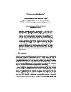
ABSTRACT Case-based reasoning (CBR) is an AI technique that emphasises the role of past experience during future problem solving. New problems are solved by retrieving and adapting the solutions to similar problems, solutions that have been stored and indexed for future reuse as cases in a case-base. The power of CBR is severely curtailed if problem solving is limited to the retrieval and adaptation of a single case, and for this reason the strategy of reusing multiple cases is immediately appealing. This paper describes the technique of hierarchical case-based reasoning, which allows complex problems to be solved by reusing multiple cases at various levels of abstraction. The technique is described in the context of Déjà Vu, a CBR system aimed at automating plant-control software design.
1 B. Smyth is with the Department of Computer Science, University College Dublin, Belfield, Dublin
4, IRELAND, Email:
[email protected], WWW: http://cs-www.ucd.ie/staff/html/barry.html 2 P. Cunningham is with Department of Computer Science, Trinity College Dublin, Dublin 2,
IRELAND, Email:
[email protected] 3 M. T. Keane is with the Department of Computer Science, Trinity College Dublin, Dublin 2,
IRELAND, Email:
[email protected]
1
I N T R OD U C T I ON
In contrast to traditional first-principles artificial intelligence (AI) systems, which solve problems “from scratch”, case-based reasoning (CBR) emphasises the role of past experience and reuse during problem solving. New problems are solved by retrieving and adapting the solutions to similar problems, solutions that have been stored and indexed for future reuse as cases in a case-base. The power of CBR is severely curtailed if problem solving is limited to the retrieval and adaptation of a single case. For complex problem domains, it is unlikely that a single case will be available which closely matches all of the target problem details, and hence sophisticated adaptation support will be necessary. However, the same problem may be more readily solved by combining parts of many different solutions, without the need for the same level of sophisticated adaptation. For this reason, the strategy of reusing multiple cases is immediately appealing.
There are two important related issues that must be considered to support multiple-case reuse: (1) Should complex problems be represented as single, large cases, or as inter-related collections of simpler cases? (2) During problem solving, how can complex new problems be broken up into simpler sub-problems which can be solved by the retrieval and adaptation of individual cases?
The paper reports on a novel technique called hierarchical case-based reasoning (HCBR) used in a software design system called Déjà Vu ([28],[29],[30],[31]). Déjà Vu solves complex plant-control (PC) software design problems by reusing multiple cases at varying levels of abstraction. Plant-control software designs are stored, not as single cases, but as hierarchies of cases. These hierarchies are made up of abstract cases (offering high-level solutions or “rough” designs) and concrete design cases (containing actual plant-control code). This organisation makes it possible to do three things: (1) Decompose target problems into simpler sub-problems; (2) Reuse parts of complex problems as individual cases; (3) Recombine solution parts into a coherent whole.
This paper describes hierarchical case-based reasoning in the context of Déjà Vu, focusing on the technique’s knowledge requirements, main algorithms, and its beneficial implications. The next section briefly introduces the Déjà Vu system and the plant-control software domain. Section 3 motivates the hierarchical reuse of multiple cases by drawing on planning research. Section 4 goes on to explain Déjà Vu's case representation and hierarchical case-base organisation, while section 5 describes the HCBR process model. CBR is an important machine learning technique and case learning within the HCBR framework is the subject of section 6. Section 7
1
traces through an example HCBR session, and section 8 discusses the main benefits and expected applicability of HCBR. Finally section 9 describes related work reported in the CBR literature.
2
D É J À V U & T HE P L A N T -C ON T R OL D OM A I N
Many industrial environments today have been partially automated by the use of device-control or processcontrol software, which is well suited for tasks such as the control of robot equipment or environmental sensing and monitoring. Plant-control software is used in factory environments such as steel mills to control milling equipment during the steel production process [8]. Automating the design of this type of software is an important and challenging research task [13] because of the current overwhelming need for high quality software [7]. While there have been some successful demonstrations of partial automation in this area ([3],[8],[22],[27],[40]), on the whole progress has been slow and limited. The main focus of the Déjà Vu project has been to investigate the potential for CBR to improve matters, and by way of a demonstration, to build a case-based system for automating the design of steel-mill control software.
2.1 An Overview of the Plant-Control Domain
Plant-control software is software for controlling autonomous, robotic vehicles within steel-mills. These vehicles are called coil-cars and they travel throughout the steel-mills on a series of interconnecting tracks. As shown in Fig. 1(a) the layout of these tracks and the placement of various devices can vary from steel-mill to steel-mill.
(a)
CC-2
TR-2
(b)
SENSOR
TENSION-REEL SPOOL/ COIL
SKID-2
JUNCTION-1 SKID
COIL-CAR Forward
Raise/Lower Backward
TR-3
Fig. 1. (a) A sample mill layout showing the location of various plant machinery. (b) The load/unload task scenario, whereby a coil-car is used to unload (load) spools or coils of steel between skids and tension-reels.
Coil-cars can be directed to travel in particular directions and at certain speeds. Their main task is to carry spools
2
and coils of steel from one section of the plant to another. The next two most important devices in a steel mill are the tension-reels and the skids (as shown in Fig. 1(a)). A tension-reel is a piece of equipment that feeds a coil of steel into a milling press. A skid is a holding area for empty spools.
For the most part, the type of tasks that will be examined in this work are loading and unloading tasks. These tasks are concerned with loading or unloading spools and coils of steel to and from the skids and tension-reels. For example, one common task calls for the unloading of an empty spool of steel from a tension-reel, and its delivery to a waiting skid; see Fig. 1(b).
2.2 Plant-Control Software
The software code that is needed for loading or unloading task is very complex. For example, the vehicle involved in the task must be controlled as it travels to and from the appropriate machinery, coils or spools of steel have to be loaded onto and unloaded from this vehicle, and various sensory data must be continually monitored to determine certain operational features such as vehicular location and speed. As Fig. 1(b) indicates coil-cars, tension-reels, and skids are complex devices, made up of a number of components, which themselves must be individually controlled.
Plant-control software code is represented as sequential function charts (SFCs), a high-level graphical source language representation. Programs correspond to interconnected graphs, control flow being dictated by the interconnection scheme, and individual commands corresponding to actual graph nodes. These graphs can implement sequential or parallel control-flow making them highly suitable for real-time control tasks. For example, a coil-car buggy may be moved towards a tension-reel at the same time as its lifter is lowered into place. A simple stepping logic program is shown in Fig. 2. The program demonstrates how a coilcar (CC-1) is moved in a forward direction to a tension-reel (TR-1), using two speed motion.
The basic move and stop actions are shown as action nodes, while two sensor check nodes are used to detect the arrival the coil-car at its slowing down point and its final destination. Note that the sensor check nodes are connected to the main logic stream by AND connectives. This synchronises the two speed motion, and ensures, for example, that the coil-car does not slow down until it reaches the correct distance from the destination. The inserts in Fig. 2 expand two of these nodes to show how their precise details are represented in the system.
3
SFC*2
SFC*2
Type Check
: Check : Distance-Check
Input Output
: : SFC*3
Device Destination Orientation Distance
: : : :
SFC*5
CC-1-Buggy At 200mm Before TR-1
CC-1-Buggy At TR-1
SFC*1
SFC*4
Move CC-1-Buggy Fast Forward
SFC*3
CC-1-Buggy TR-1 Before 200mm
SFC*7
Move CC-1-Buggy Slow Forward
Stop CC-1-Buggy
SFC*6
SFC*1 Type
: Action
Input Output
: *START* : SFC*3
Action Device Direction Speed
: : : :
Move-Device CC-1-Buggy Forward Fast
Fig. 2. A sample program for moving CC-1 forward to TR-1 using two speed motion.
The program shown in Fig. 2 represents just one small part of a complete UNLOAD program which would also include code segments for aligning the coil-car and the tension-reel, unloading the empty spool of steel, and delivering this to the waiting skid. These operations are themselves composed of many simpler code segments like the one shown in Fig. 2. In all, a typical UNLOAD program will contain approximately 100 individual commands.
3
H I E R A R C HI C A L , M U L T I PL E -C A S E R E U S E
Solving complex problems by decomposition is a common strategy which is appealing for much the same reason that macros and subroutines are appealing in programming; problems can be solved more easily by breaking them into manageable chunks, rather than trying to solve them “all in one go” ([5],[15]). Thus, the extension of singleshot case-based reasoning systems to multiple-case reuse systems is a natural one. Many of the systems that have implemented multiple-case reuse have drawn on ideas from more traditional first-principles planning research. However, the transfer of ideas from first-principles to case-based methods is not a straightforward one, and a
4
number of issues must be resolved that impact on how cases are represented and organised, before we can support their combined reuse.
3.1 Towards Hierarchical Reuse in Case-Based Reasoning
Early goal-directed problem solving systems used decomposition to break up complex problems into collections of individual sub-goals. Each goal is separately planned for, generating a number of separate plan segments (a partial-order plan), which are combined to produce the final complete solution (a total-order plan). Unfortunately, depending on how partial plans are combined, interactions and conflicts between planning operators may or may not pose a serious threat to success; for example, plan segments to satisfy goal A and goal B might work fine when taken in isolation, but taken together they may conflict, preventing both goals from being simultaneously satisfied ([20],[37],[38],[25]). The first case-based reasoners to employ multiple-case reuse did so in a fashion that was analogous to early goal-directed decomposition. Redmond [23] describes a system that solves diagnosis problems by reusing many single cases to solve individual target sub-goals, and the final solution is constructed by chaining together these cases (for further details see section 9).
Early goal-directed planners carried out their search at a single level of abstraction; the level of primitive operators. Difficulties arose because the space of plans was so huge that brute-force search often failed to find suitable plans within acceptable time bounds; these planners would spend large amounts of time on fine-grained plan details, without considering how a more abstract perspective might better focus search. Once the usefulness of abstraction was recognised, researchers began to consider the idea of hierarchical planning ([24],[26],[34]). These planners employed a hierarchy of problem spaces, called abstraction spaces, to restrict search and deal with problematic goal interactions early on. Abstract plans, made up of abstract operators, are first created to act as “skeletal” or outline solutions. As planning proceeds these plans are refined through successive levels of abstraction by replacing their abstract operators with collections of more detailed (less abstract) operators. Eventually, a complete plan is built which contains only primitive operators. Studies have shown that such hierarchical approaches can significantly reduce search while developing high quality solution plans ([1], [11]).
5
3.2 Introducing Hierarchical Case-Based Reasoning
Hierarchical planning has motivated the development of hierarchical case-based reasoning, which also solves problems within a hierarchy of abstraction spaces, by storing, retrieving, and adapting abstract cases as well as concrete design cases. By analogy with hierarchical planning, abstract cases are made up of abstract operators, while design cases are made up of primitive operators. One of the central concepts in HCBR is that abstract cases offer much more than just abstract solutions. As we shall see, their abstract operators can be viewed as subproblem specifications, and used to decompose complex problems into collections of simpler sub-problems.
The decision to retain and reuse abstract cases offers a number of advantages. Firstly, the search reduction witnessed in traditional hierarchical planners is transferred to case-based methods. However, it is manifested differently, as it corresponds to a reduction in matching and adaptation costs, rather than a reduction in conventional search costs. Furthermore, the idea of preserving abstract solutions, and in particular the idea of promoting these solutions as sub-problem specifications, suggests a novel indexing technique, whereby detailed cases are indexed in terms of more abstract cases.
Problem A
Problem B
Abstract Case
Concrete Case
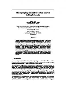
Fig. 3. Problems A and B are represented by two case hierarchies which are interconnected because they share a similar sub-problem and hence similar solution components. Allowing cases to interconnect in this way means that complex solutions can be represented very efficiently, without duplication.
Using HCBR, each complex problem is actually represented in the case-base as a case hierarchy which is made up of abstract cases and concrete design cases. Thus, the case-base is no longer viewed as a loosely connected collection of cases, but instead as a set of highly structured case hierarchies. Furthermore, a number of hierarchies may share the same sub-hierarchies, or individual cases, to reflect the fact that similar problems have similar solution parts. This leads to interconnections between case hierarchies and greatly reduces redundancy
6
within the case-base. For instance, one example of sharing between case hierarchies is shown in Fig. 3, which illustrates the solution structure of two problems, sharing common solution components. However, this sharing is only possible when the solutions are represented in a hierarchical fashion as a collection of individual cases. Indeed, using conventional approaches, and representing each problem as a single, monolithic case, necessarily means having to represent the shared solution components twice in the case-base.
4
C A S E R E P R E S E N T A T I ON S
Usually cases are represented in two parts, a description part and a solution part. The description part is basically a set of features describing the solution task. Design case solutions are plant-control sequential function charts, and the same representation is used for the solutions of abstract cases, although some extensions are necessary to support the idea of abstract solution operators (or commands). The hierarchical organisation of the case-base is a direct result of the way in which abstract and design cases are represented.
At the moment the onus is on the knowledge-engineer to build suitable case hierarchies from abstract and design cases. This adds to the knowledge engineering from a case-base building perspective. However, it must be recognised that hierarchical CBR greatly reduces the adaptation overhead and, we argue, greatly reduces the more difficult knowledge-engineering task of encoding suitable adaptation knowledge structures. This will be discussed further in section 8.
4.1 Describing Cases
Certain case solutions can be described in terms of simple goals and contexts while others may address multiple (possibly interacting) goals with overlapping contexts. To capture this range of possibilities Déjà Vu uses a taskstructured representation scheme. Cases are defined according to the type of plant-control task they carry out. Each task has a well defined top-level structure and may achieve a number of different goals. Moreover, tasks group together the plant-control devices that partake in a specific operation, and the roles that they play.
In more concrete terms, each case specification is represented as a collection of frames (see Fig. 4). A header frame describes the case task structure and introduces its main features. For example, if a case performs an UNLOAD task then its task frame will be a type of UNLOAD frame. This frame will introduce the following features: a vehicle (the device performing the
unloading) a content (the coil or spool being
7
unloaded), source and target containers (where the content is being unloaded from and delivered to), and the source and target locations of the vehicle (where the vehicle begins and finishes).
The task frame is linked into the system knowledge-base and plant-models where it points to frames that correspond to the domain entities involved in the task. These entity frames provide additional details. For example, the vehicle used in Fig. 4 is a coil-car, CC-2, which has featuers that are important during the UNLOAD solution. For instance, the slowing distance of the CC-2’s buggy is significant during any MOVE sub-problems.
Obviously, to fully specify an UNLOAD program it is not sufficient to simply state the vehicle, the content, the locations, and the containers involved, and clearly these features do not fully determine the internal structure of the final solution. However, because problems are represented at multiple levels of abstraction, many details will be omitted from the high-level cases, but introduced by lower-level cases. For instance, one sub-problem of the UNLOAD task is concerned with moving the vehicle to the source container, and in this MOVE sub-problem additional features, such as the required speed of motion, will be specified. CC-2
TASK-0 Type
: Unload
Vehicle Content
: CC-2 : Spool-2
Type
: Coil-Car
Buggy Lifter Socket
: CC-2-Buggy : CC-2-Lifter : CC-2-Socket
CC-2-Lifter
Source-Loc : Skid-2 Target-Loc : TR-2
: Lifter
Speed
: 2-Speed
Slowing-Dist : 300mm Lower-Limit : 100mm Upper-Limit : 1000mm Carrying-Limit : 500mm
Source-Cnt : TR-3 Target-Cnt : Skid-2 CC-2-Buggy Type
Type
: Buggy
Speed-Type : 2-Speed Slowing-Dist : 300mm
Fig. 4. Part of a case task structure that describes a specific UNLOAD solution. The task frame describing the UNLOAD problem is linked directly to device and component frames which describe the UNLOAD coil-car, CC-2.
4.2 Representing Abstract Solutions
8
The representation of a concrete design case is straightforward. It contains a task description and a plant-control solution chart. The representation of an abstract case is complicated by the fact that it must contain an abstract solution. For example, consider the problem of collecting a coil of steel from a skid using a coil-car. An abstract case for this problem contains abstract operators that describe actions such as moving the coil-car to the skid, aligning the coil-car’s lifting platform with the coil, and finally releasing the coil onto the coil-car. Representing the same problem as a primitive design case means specifying how the coil-car moves to the skid in terms of its direction and speed, when it should slow down, when it stops, what track junctions it crosses, and so on.
Two extensions must be made to the existing solution representation language to support abstract cases. Firstly, a technique for describing the structure of abstract solutions is needed. The plant-control solution structures of design cases are represented using the sequential function chart formalism introduced in the previous chapter, and fortunately this formalism can be easily extended to cover abstract cases as well. All that is needed is one new type of node, called a link-descriptor node, to store abstract operator details; these are drawn as octagonal nodes in future solution graphs. There are many advantages to be gained from reusing the SFC formalism to represent abstract case solutions. Obviously, both sequential and parallel actions can still be represented, but also, when it comes to adapting solutions, the same basic adaptation operators can be used to change both abstract and concrete solutions.
The second extension deals with how to specify the contents or details of an abstract operator. Currently there are no plant-control commands that can represent the high-level operations of an abstract solution. Again, the answer is already at hand, in the form of task structures. Each type of task structure defines a different type of abstract operator. For example, an abstract operator for specifying a particular MOVE task is an instantiation of the MOVE task structure, specifying details such as the vehicle, speed, locations and so on. This means that during problem solving, the abstract operators can be treated as case specifications, as well as high-level solution code. Consequently, abstract solutions can be used to facilitate problem decomposition, their abstract operators defining new sub-problem specifications, which will be solved by the retrieval and adaptation of more detailed cases. In this way the solutions of Déjà Vu’s abstract cases are similar to the abstract solution plans often used by the planning community. This form of operator abstraction is also used by Bergmann & Wilke [2].
4.3 Case Hierarchies
9
We have already introduced the idea that complex problems are to be represented as hierarchical collections of abstract and design cases. It is important at this stage to emphasise that these hierarchies are not automatically created by Déjà Vu. Instead, they must be engineered from complex cases, and so this form of hierarchical casebased reasoning increases the knowledge engineering cost of CBR. However, there is promising research available that leads us to believe that it may be possible to automatically generate these hierarchies ([2], [6], [12]). Furthermore, as we will discuss in section 8, there are also distinct advantages associated with HCBR, including a reduced need for adaptation knowledge, and corresponding decrease in the knowledge engineering effort associated with the compilation of this knowledge.
Unload-1
Key: Abstract Case
Design Case
Collect-1
Park-1
Cross-4
Move-6
Lift-3
Move-5
Release-2
Disengage-2
Align-2
Engage-2
Cross-3
Move-4
Move-3
Lift-2
Disengage-1
Release-1
Engage-1
Switch-1
Move-2 Align-1 Cross-2
Cross-1
Move-1 Lift-1
Deliver-1
Fig. 5. The case hierarchy for the UNLOAD problem first introduced in section 2.
Fig. 5 shows the case hierarchy for a typical UNLOAD problem.. Each node represents a named case. In this hierarchy there are four levels of abstraction. The top-level or root case, UNLOAD-1, contains the most abstract solution to the problem. The next level describes the problem in terms of three separate tasks, collection, delivery, and parking. In turn, more cases are introduced at levels three and four for dealing with the specific parts of these tasks, such as moving the coil-car, aligning it with tension-reels and skids, and releasing spools.
The links between successive levels of case hierarchies correspond to the abstract operators found in abstract solutions. Most notably, these links are implicit and indirect. That is, abstract cases do not explicitly name their lower level cases in any way. Instead, the cases that are found linked to some abstract case are those cases that match the specification requirements laid out in its link-descriptors.
10
C Unload-1 SIDING -UNLOAD -1 Collect
O1 Deliver O2
Spool-2 from TR-2 using CC-2 at TR-3
C1
Spool-2 to Skid-2 using CC-2 at TR-2
Return CC-2 from Skid-2 to TR-2
C3
O3
C2
Collect-1 Align CC-2 Lifter with TR-2 Spool-Stand
Lower CC-2 to Lower-Limit using 1-Speed-Fast
Move CC-2 to Tk-4-Jnct-1 using 2-Speed
Cross CC-2 from Tk-4 to Tk-3
Move CC-2 to TR-2 using 2-Speed
Engage CC-2 with TR-2 for Spool-2 Release
Release Spool-2 from TR-2 to CC-2
Move-1
Disengage CC-2 from TR-2
Engage-1
CC-2 At 200mm Before Tk-4-Jnct-1
CC-2 At Tk-4-Jnct-1
Move CC-2 Fast Backwards
Move CC-2 Slow Backwards
Connect-Chk CC-2-Socket TR-2-Socket
Stop CC-2
Set CC-2 Brake On
Connect CC-2 Socket TR-2 Socket
Fig. 6. A portion of the UNLOAD hierarchy shown in Fig. 5 as it would appear in the case-base at run-time. Notice how lower-level cases are implicitly linked to their higher-level parent cases. The link-descriptor nodes are represented as octagonal nodes in the solution diagrams, distinguishing them from the standard rectangular and oval nodes of the action and sensor check plant-control commands, respectively.
An abstract case (call it C) at level i might be linked to 3 less abstract cases (call them C1, C2, C3) at level i+1. However, these 3 cases are not “mentioned” directly by the solution of case C. The cases C1, C2, C3 are linked to case C by virtue of the fact that they fit the requirements laid out by the abstract operators in case C’s solution. That is, case C1 fits the specification requirements laid out in an abstract operator O1, C2 fits those of O2, and C3 fits those of O3. In other words, C1 provides a solution for sub-problem specified by O1, and so on. This can be seen in Fig. 6, which will be examined more closely in a moment.
This indirect referencing of cases is a powerful and flexible mechanism. It means that abstract solutions can be used as indexing structures for more detailed solutions. It also means that exact matches between abstract operator specifications and cases are not strictly enforced, or required. For example, returning to Fig. 6, C1 may
11
not be an exact match for the sub-problem specified by operator O1, but as long as it can be adapted to fit O1, adequate problem coverage is assured.
The use of indirect referencing between hierarchy levels, and the flexibility to support non-exact matches between these levels, promotes storage efficiency by facilitating the sharing of cases. For example, consider a number of abstract cases each requesting a piece of code that moves a coil-car from one location to another. Each abstract case may specify a slightly different form of this MOVE task. For instance, the locations may differ or the directions of motion may differ. However, it may be possible to use the same MOVE design case to satisfy each situation, if the case can be adapted to account for the various location or directional differences.
If case-base size is a concern then this facility can represent a considerable advantage, and it means that the casebase can be optimised for performance without necessarily affecting the competence or coverage of the cases. For obvious reasons this type of sharing is not possible if compound cases are used to represent complex problems.
Returning to Fig. 6, a part of the case hierarchy for the problem outlined in Fig. 5 is shown. The solutions of 4 cases have been highlighted, and are shown in detail. UNLOAD-1 and COLLECT-1 are both abstract cases while MOVE-1 and ENGAGE-1 are primitive design cases. Notice that the structure of the final solution is inherited from higher abstraction levels, since the structure of an abstract solution at level i specifies how the more detailed solutions at level i+1 are to be connected. For example, in Fig. 7, the UNLOAD solution indicates that the solutions to its COLLECT, DELIVER and PARK link-descriptors are to be sequentially joined. On the other hand, the COLLECT solution indicates a more complex combination of solution segments, a combination that includes both parallel and sequential connections. For example, the first two operators of the COLLECT abstract solution are connected in parallel so that the coil-car may move towards the indicated track junction while at the same time adjusting its lifter height.
12
5
T HE HCBR P R OC E S S M OD E L
To make hierarchical problem solving work it must be possible to decompose a target specification into abstract sub-problems. Different approaches have been used to perform decomposition ([14],[16],[17],[19]). The main problem with adding decompositional methods to CBR, is that they introduce the need for additional knowledge sources (the decomposition knowledge), and additional procedures to perform the actual decomposition (algorithms for selecting and applying decomposition knowledge).
Compared to existing approaches, hierarchical case-based reasoning is a more complete integration of CBR and decomposition, and it does not require separate decompositional knowledge or procedures. The decompositional “know-how” is part of the case-base, and the decomposition procedure is a “side-effect” of the retrieval and adaptation of an abstract case. That is, when an abstract case is retrieved and adapted its modified linkdescriptors are used as new sub-problem specifications, and result in the retrieval and adaptation of additional cases.
The following sections will refer to the retrieval and adaptation of cases within HCBR. Unfortunately these topics lie outside of the scope of this paper. However, further information can be found in [31] and [32].
5.1 The Main HCBR Algorithm
Hierarchical case-based reasoning adds complexity to the standard CBR model, since problem solving is now an iterative process whereby many cases are retrieved and adapted, problems are decomposed, and new solution components are integrated into an evolving target solution. The HCBR algorithm is shown in Table 1.
Each HCBR cycle corresponds to the retrieval and adaptation of a single case. As a target problem is decomposed, new specifications are added to a specification queue, and during each HCBR cycle the current specification is removed from the head of this queue. Decomposition only occurs if an abstract case is reused (retrieved and adapted), its abstract operators corresponding to the new specifications that are added to the queue.
As new sub-problems are decomposed and solved, the overall target solution is built up. During
integration, each newly adapted solution (abstract or concrete) is added to the evolving target solution, which itself takes the form of an abstraction hierarchy.
13
Inputs: Target-Spec : The initial target specification CB
: The Case-Base
A-KN
: The Adaptation Knowledge
Outputs: Target-Sol
: The complete target solution.
Procedure HCBR (Target-Spec, CB, A-KN) Begin 1
Spec-Q ← {Target-Spec}
2
Until Empty?(Spec-Q) Do
3
Current-Spec ← First(Spec-Q)
4
Current-Base ← RETRIEVE(Current-Spec, CB, A-KN)
5
Current-Sol ← ADAPT(Current-Spec,Current-Base,A-KN)
6
If Abstract?(Current-Base) Then
7
Spec-Q ← DECOMPOSE(Current-Sol, Spec-Q)
8
End-If
9
Target-Sol ←INTEGRATE(Current-Spec,Current-Sol,Target-Sol)
10
LEARN (Current-Spec,Current-Sol,Current-Base)
11
End-Until
12
Return(Target-Sol)
End
Table 1. The Hierarchical Case-Based Reasoning Algorithm
5.2 Decomposition
The main point about the decomposition process is that it is essentially a direct extension of the retrieval and adaptation of an abstract case (Table 2). An adapted abstract solution contains certain link-descriptors that describe sub-problem specifications relevant to the current problem, and during decomposition these linkdescriptors are extracted and added to the main specification queue. For reasons of generality and flexibility there are no hard-wired constraints which control how new problem specifications are added to the queue during decomposition. In the current system, new specifications are added to the head of the queue, thereby implementing a depth-first search of the abstraction space. However, different queuing policies can be enforced depending on the application and domain requirements; for instance, new specifications can be added to the end of the queue to implement a breadth-first search, or various sorting methods can be used (either before or after
14
queuing) to implement hill-climbing or branch-and-bound type searches.
Inputs: Current-Sol : The adapted abstract solution Spec-Q
: The specification queue
Outputs: Spec-Q’
: The new, updated specification queue.
Procedure DECOMPOSE (Current-Sol, Spec-Q) Begin 1
Sub-Specs ← {}
2
For each Node ∈ Nodes(Current-Sol) Do
3 4 5
If Link-Descriptor?(Node) Then Sub-Specs ← Sub-Specs ∪ Details(Node) End-If
6
End-For
7
Spec-Q’ ← Combine(Sub-Specs,Spec-Q)
8
Return(Spec-Q’)
{Eg, Spec-Q ←Sub-Specs ∪ Spec-Q}
End
Table 2. The Decomposition Algorithm.
5.3 Integration
The overall target solution is constructed during integration as new solution components (abstract or concrete) are combined (Table 3). The evolving target solution is an abstraction hierarchy that corresponds to the hierarchical structure of the target problem.
After the first HCBR cycle, the target solution contains the newly adapted solution of the first case retrieved. During subsequent cycles new solutions will be attached to the link-descriptor nodes of this initial solution, as more detail is added. This attachment is made efficient by labelling link-descriptors during decomposition and passing these labels with their sub-specifications to retrieval and adaptation. When it comes to integrating a new solution its label is easily located, and the solution can be inserted.
During integration, attachments must also be made between new solution components and adjacent sibling components. Furthermore, it is not sufficient to simply connect sibling solutions in sequence. The appropriate
15
connection information is stored within the structure of the parent abstract solution and must be used to guide the connection process.
Inputs: Current-Spec: The current specification Current-Sol : The current solution Target-Sol
: The target solution tree
Outputs: Target-Sol
: The updated target solution tree
Procedure INTEGRATE (Current-Spec,Current-Sol,Target-Sol) Begin 1
Parent-Node ← Locate(Current-Spec,Target-Sol)
2
Sibling-Nodes ← Locate-Siblings(Parent-Node,Target-Sol)
3
Target-Sol ← Parent-Attach(Parent-Node,Current-Sol)
4
Target-Sol ← Sibling-Attach(Sibling-Nodes,Current-Sol)
5
Return(Target-Sol)
End
Table 3. The Integration Algorithm
An example of integration is depicted in Fig. 7 which shows three layers of abstraction. The top-level contains an abstract solution with three sequentially connected link-descriptor nodes. Subsequent HCBR cycles produce three second-level solutions which are linked to each of the top-level link-descriptor nodes, and connected together in sequence as directed by the top-level solution structure. Part of the third level of abstraction is shown which corresponds to the concrete plant-control code of three design cases, connected together according to their
Abstract Cases
parental solution structure; this time two of the design solutions need to be connected in parallel.
Design Cases Fig. 7. Part of an evolving solution tree.
16
6
LEARNING
IN
HCBR
One of the main advantages of CBR is its simple, but powerful, form of learning. As new problems are solved their solutions can be learned by repackaging them as cases and adding them to the case-base. However, this allor-nothing approach has its problems, mainly because entire solutions must be learned even if only a small part is novel enough to warrant addition into the case-base. HCBR offers a new twist on case learning by facilitating the learning of relevant solution parts without imposing the need to learn entire solution structures.
6.1 Learning New Cases
After retrieving and adapting a case to produce a new target solution, the simplest way of learning is to package the target specification and solution as a new case, and to insert it into the case-base. The basic assumption is that learning new cases will improve system performance by making more cases available during problem solving, and therefore increasing the likelihood of finding a relevant case with which to solve future target problems. Unfortunately, one of the side-effects of this simplistic approach to learning is that it can cause system performance to degrade rather than improve. This effect is known as the utility problem and has been the subject of considerable research by the machine learning community ([18],[21],[35],[36],[39]), and more recently, by case-based reasoning researchers ([9],[10],[30]).
In general, the utility problem describes how the performance of knowledge-based systems can degrade if the knowledge-base becomes populated with “harmful” or redundant knowledge items. In case-based reasoning this can happen if new cases are learned without due care or attention being paid to their quality, or to their relationship with existing cases in the case-base. For example, if a very similar case already exists, then the new case may offer no performance advantages. By over-populating the case-base in this way, increasing retrieval costs will eventually degrade overall system efficiency.
There is a straightforward way to avoid adding redundant cases to the case-base which goes a long way to reducing the damaging effects of the utility problem: cases should only be learned if they are substantially different from the existing cases. This can be verified by checking the adaptation distance between the target and the base case; that is the cost of adapting the retrieved case to fit the target problem. If this cost is less than some predefined threshold then cases already exist which can very easily solve the target problem, and so the new case is not needed. However, if it is greater than the threshold then the target cannot be solved without significant
17
adaptation effort, and so the new target case should be learned (see Table 4).
Inputs: Target-Spec : The current target specification Target-Sol
: The new target solution
Base-Case
: The retrieved case
CB
: The case-base
Outputs: CB’
: The new case-base after learning
Procedure LEARN (Target-Spec, Target-Sol, CB) Begin 1
Adaptability ← Adaptability (Target-Spec, Base-Case)
2
If Adaptability > *ADAPTABILITY-THRESHOLD*
3
Target-Case ← MakeCase (Target-Spec, Target-Sol)
4
CB’ ← InsertCase (Target-Case, CB)
5
End-If
6
Return(CB’)
End
Table 4. The basic case learning algorithm.
6.2 Learning Case Hierarchies
The threshold-based learning idea is commonly used in many standard, single-shot case-based reasoning systems. Of course the hierarchical CBR model introduces an added dimension to learning because during the solution of a target problem there are many learning opportunities. With each HCBR cycle a new case (abstract or design) can be learned (see Algorithm 1), and this in turn means that new case hierarchies (complete or partial) can be acquired.
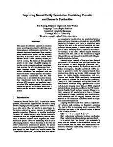
Fig. 8 illustrates how partial case hierarchies can be learned and linked into the existing case hierarchies. Two existing case hierarchies (A and B) are shown. Four new cases are learned as a new partial hierarchy, whose missing cases are to be found in A and B.
18
Hierarchy A
Hierarchy B
Abstract Case
Concrete Case
Fig. 8. Partial case hierarchies can be learned if their missing cases are readily available as part of existing hierarchies. Two existing hierarchies (A and B) are shown in grey. A new partial hierarchy is shown in black and links to various cases in A and B; the newly learned cases are highlighted with shading.
In particular, this facility for selectively learning parts of more complex solutions, ensures that case redundancy is limited during learning. In contrast, single-shot CBR systems have an all-or-nothing approach to learning; either an entire new solution is learned as a new case or it is not. Frequently however, only part of such a complex solution will be genuinely worth learning as many parts of it may already exist in other cases. So single-shot systems can increase redundancy if they learn new cases
7
A N E XA M PL E
The following is a description of part of a problem solving episode illustrating the basic operation of hierarchical case-based reasoning. The example problem is to UNLOAD an empty spool (SPOOL-2) from a tension-reel (TR-2) and deposit it on a skid (SKID-2); this problem is situated in the plant model shown in Fig. 1(a). The top-level (abstract) case that is retrieved is an INSERT case; a coil stored on TR-3 is inserted into TR-2. UNLOAD and INSERT tasks are similar in many ways, particularly at this high level of abstraction. For instance, both types of problem can be broken into common COLLECT and DELIVER sub-tasks. In this example the only adaptations necessary to the retrieved abstract solution are substitutions which account for differences in the load object (replacing a coil with a spool) and the source and target containers.
Fig. 9 shows part of the case hierarchy for the INSERT problem. After retrieving the top-level INSERT case, its adapted solution is decomposed and integrated into the overall target solution. During decomposition the COLLECT and DELIVER link-descriptors (which have of course been modified to fit the target) are extracted and queued, where they will be used during future HCBR cycles.
19
Consider what happens when the DELIVER sub-specification is served from the queue. Suppose further, that it results in the retrieval of the DELIVER case belonging to the original base INSERT hierarchy. The target delivery requirements specify the delivery of an empty spool, whereas the retrieved delivery case caters for the delivery of a full coil of steel. Insert Deliver Coil-2 to TR-2 using CC-2 at TR-3
Collect Coil-2 from TR-3 using CC-2 at Skid-2
Deliver
Lift CC-2 to Carry-Level using 1-Speed-Slow
Lift
Move CC-2 to Junction-1 using 2-Speed
Move
CC-2-Lifter At Carry-Level
Move CC-2-Lifter Slow Downwards
Sequential execution due to coil carrying restriction
CC-2-Buggy At 200mm Before Tk-4-Jnct-1
Stop CC-2-Lifter
Move CC-2-Buggy Fast Backwards
CC-2-Buggy At Tk-4-Jnct-1
Move CC-2-Buggy Slow Backwards
Stop CC-2-Buggy
Fig. 9. Part of an INSERT case hierarchy highlighting how the sequential connection of link-descriptor nodes in the DELIVER case is inherited by the corresponding lower level LIFT and MOVE design cases.
Now, one of the implications of carrying a full coil of steel is that coil-car movement and lifting operations cannot be carried out in parallel, for plant safety reasons. This can be seen in the base delivery solution shown in Fig. 9; the link-descriptors for the MOVE and LIFT sub-tasks are connected in sequence resulting in the serial connection of the corresponding MOVE and LIFT plant-control code segments. If a coil-car is carrying a spool however (as it is in the target problem) then lifting and moving can be performed in parallel. Therefore, changes will need to be made to the retrieved delivery solution to re-order the delivery link-descriptors to support this
20
parallel structure; this is illustrated in Fig. 10 where an adaptation to the DELIVER case ensures that the subsequent design cases are organised correctly. Of course many more adaptations are also needed, but for the sake of clarity these are left out of this example.
Unload Parallel execution due to removal of coil carrying restriction
Deliver
Adapt (Re-Order)
Lift
Move
Fig. 10. A portion of the evolving target solution tree highlighting how a high-level adaptation of an abstract case can save considerable work during the future adaptations of lower level cases.
The re-ordering adaptation is typical of the type of interaction problem that can occur when multiple cases are reused in combination. It is seen in many design and planning domains, not just plant-control software. Déjà Vu's coping strategy is to deal with such interactions early on, during adaptation, instead of later, during integration,
21
and this can lead to significant adaptation savings. For instance, by adapting the abstract delivery solution the reordering problem was solved by rearranging two solution nodes (which happened to be link-descriptors). If a lazy resolution policy is enforced instead, and the re-ordering is delayed until integration time, then a more complex adaptation will be required, since the entire MOVE and LIFT solutions will have be re-ordered; that is, seven nodes instead of two must be re-ordered.
Returning to the example: having adapted the delivery case and integrated it into the target solution tree, decomposition again occurs as the link-descriptors of the DELIVER solution are extracted and queued. The solution specifies the need for a LIFT and a MOVE case, and in contrast to the earlier HCBR iterations, these specifications result in the retrieval and adaptation of concrete design cases rather than abstract cases. Furthermore, the retrieved design cases do not come from the original INSERT hierarchy because more suitable cases exist as part of another hierarchy. These are retrieved and adapted and their solutions integrated into the target solution. The final and complete target solution can then be constructed from the design cases at the leaf nodes of the solution tree.
8
D I S C U S S I ON
There are a number of advantages to supporting hierarchical case-based reasoning. Firstly, it is an elegant way of integrating decompositional and case-based design techniques. Secondly, the support of multiple-case reuse reduces the adaptation burden, facilitating the solution of complex design problems. Thirdly, the hierarchical case-base improves storage efficiency by eliminating redundancy. Finally, the additional knowledge-engineering effort due to the construction of the case hierarchies is offset by a reduced need for adaptation, and subsequently the knowledge-engineering cost for adaptation knowledge is greatly diminished.
8.1 The Benefits of Case-Based Decomposition
In HCBR, decomposition occurs because abstract cases are retrieved, and the specific type of decomposition depends on how these cases are adapted. This marrying of decomposition and case knowledge means that the problem decomposition and solution generation sides of HCBR are always properly synchronised, and suggested decompositions can always be filled by available cases.
The
conventional
strategy
for
integrating
decompositional and case-based methods has been to
22
dovetail the two techniques, and to provide a mechanism for switching between each one (e.g., [16],[17]). Such systems use different sources of knowledge for each problem solving technique and serious problems can arise if these sources are not fully compatible, or not properly synchronised. For example, a decomposition can be suggested, for which there are no suitable cases in the case-base. Obviously, HCBR avoids this problem because the cases and the decomposition knowledge are fully integrated, and since future decompositions are always carried out by adapting parts of existing case hierarchies.
8.2 Reducing the Adaptation Load
Single-case reuse in a plant-control software design system such as Déjà Vu is not viable. Case-based reasoning can solve a new target problem only if there is a case which is similar enough to reuse without the need for complex adaptation. If single-case reuse was used by Déjà Vu, then guaranteeing the retrieval of a single case that was sufficiently similar to the target problem, would mean providing a huge case-base and complex adaptation knowledge. However, with a multiple-case reuse technique, the same competence and performance is possible with a much smaller case-base, as long as access is provided to individually reusable parts of complex solutions.
Returning to the previous example we saw that an INSERT case was retrieved during the solution of an UNLOAD case. This INSERT case was similar to the UNLOAD problem at a high-level of abstraction but differed considerably at lower levels. Part of the full INSERT solution could be correctly adapted to meet the target specification needs, but other parts could not. The result was that the INSERT solution could not be used in its entirety, instead additional, easy to adapt, solution parts were selected from other hierarchies. In a single-shot CBR system it would not be possible to avail of these solution parts from other hierarchies, and so problem solving would terminate after failing to properly adapt the complete INSERT solution. Therefore, using HCBR, Déjà Vu can solve a wide range of complex plant-control problems without the need for huge case-bases or extremely sophisticated adaptation methods.
8.3 Case Redundancy
Case-bases often contain redundant cases or at least partially redundant cases. Moreover, redundancy within large, over-populated case-bases can have an adverse effect on system performance leading to the utility problem (see also, [9],[10], [21], [30]). If HCBR helps reduce redundancy then it will improve the memory and
23
performance characteristics of a system, and thus help to avoid this problem.
An early observation that can be made about plant-control software concerns its degree of modularity: plantcontrol programs (such as UNLOAD or INSERT type programs) are highly modular, containing many commonly occurring sections of code; for example, most complex programs involve code to move a vehicle from one location to another. Storing complex problem solutions as single cases means repeating these recurring solution segments in each case. Storing complex solutions as interconnected hierarchies of cases eliminates this wasteful repetition by permitting case parts to be stored individually, but referenced by any appropriate case.
Matching efficiency is also improved with HCBR because during retrieval shared cases are only matched against the target specification once. Using single, monolithic case representations, duplicate structures are repeatedly matched against the target specification, as retrieval compares each monolithic case to the target.
8.4 Applicability and Knowledge-Engineering Issues
Hierarchical case-based reasoning should be chosen when certain problem characteristics hold. In an application domain that demands complex problem solutions, the standard, single-shot model of CBR is unlikely to prove successful without the use of prohibitively large case-bases. Consequently, some method for reusing parts of many solutions (such as HCBR) is needed to reduce the size of the case-base and relieve the adaptation burden.
To engineer suitable case hierarchies it is important that complex problem solutions can be decomposed into collections of simpler sub-problem solutions. Moreover, the solutions to these simpler problems should not interact with one another, or should only interact in a limited way. Fortunately, many domains and applications do benefit from decomposable solution structures, as is evident from the popularity of hierarchical problem solving and decompositional design techniques in general.
Obviously the requirement for having a highly structured case-base, which is made up of case hierarchies instead of independent cases, adds to the knowledge engineering effort during the case acquisition phase of system design. However, through this paper it has been argued that hierarchical CBR significantly reduces the adaptation burden on a CBR system. In fact, although more effort is required to engineer the case hierarchies, this is easily offset by the need for much simpler, and more easily engineered, adaptation knowledge. Indeed, it is our contention that the adaptation requirements of a traditional single-shot CBR system for sophisticated design
24
problem solving are impractical.
9
R E L A T E D W OR K
Hierarchical case-based reasoning is one way of supporting multiple-case reuse. Its distinguishing features include: (1) Using case hierarchies to represent complex problem solutions; (2) Using abstract case solutions to act as the decomposition knowledge; (3) Promoting the reuse of cases from different case hierarchies in order to reduce the adaptation overhead. While related work has produced a variety of case-based methods following a similar theme, Déjà Vu is unique in that it is the first system to successfully combine all three features.
Redmond [23] implements multiple-case reuse in an automobile diagnosis system called CELIA. Complex problem solutions are stored as collections of cases, called snippets. Each snippet’s solution contains the actions taken in the pursuit of a single goal and the results of these actions. Each snippet is represented at the same level of abstraction as every other snippet. The goal structure of a problem is preserved by directly linking snippets together, which leads to a coded bias towards sequential snippet access during reuse. That is, CELIA prefers to directly follow snippet links when solving each successive goal, and therefore tries to reuse complete solutions rather than continually searching for the best possible case. A snippet from another problem is only reused if the original snippet fails to be adapted correctly. Redmond’s research confirms the value of multiple-case reuse. Furthermore, representing problem solutions as groups of snippets is similar to the idea of using case hierarchies in Déjà Vu, except that goal-directed problem solving is supported in favour of hierarchical problem solving. However, the implicit commitment by CELIA to reuse the cases from a single problem whenever possible, means that potential adaptation savings may be lost if a more suitable case exists as part of another snippet group. Déjà Vu, on the other hand, will always try to reuse the most suitable case to solve a sub-problem.
Sycara and Navinchandra [33] also concur with the goals of multiple-case reuse in their automated design system called CADET. However, they argue that fragmenting complex designs into loosely coupled collections of cases is not appropriate because CADET’s domain, mechanical device design, is highly interactive, and robust sub-goal decompositions cannot be identified a priori. Consequently, complex cases are stored in their entirety, and their reusable parts are individually indexed using elaborate behavioural and thematic indexing structures. It is argued that the preservation of complete cases is necessary to encode the fundamental design principles embodied within
25
complex solution designs; for example, individual components are often meshed to work efficiently together as part of the larger design, and may implicitly exploit, or compensate for, various solution interactions. Sycara and Navinchandra claim that case fragmentation means throwing away much of this implicit knowledge. Of course this is not necessarily true, and the preservation of this type of structural information is the reason why Déjà Vu retains abstract solutions. These solutions contain information about how more detailed cases can be effectively combined and reused. The main difference between CADET and Déjà Vu is a representational one: CADET’s monolithic cases with complex indexing structures versus Déjà Vu hierarchical, fragmented case-base. In the end, Déjà Vu’s HCBR approach has the advantage of using abstract cases to guide decomposition, an advantage that is not immediately available to CADET. Furthermore, the ability to adapt abstract solutions to act as targetspecific decomposition templates is unique to Déjà Vu.
CADSYN ([16],[17]) is a CBR system for architectural design which, like Déjà Vu, proposes an integrated model of design by combining case-based and decompositional techniques. However, while Déjà Vu presents a tightly coupled integration of these techniques, CADSYN’s approach is a more loosely coupled affair. In brief, at each stage during CADSYN’s iterative design process, the current problem can be solved by using either case-based or decomposition methods. The choice is mediated by a similarity thresholding technique so that if a suitable case is not found, the decomposition module is invoked. CADSYN’s decomposition module draws upon knowledge and techniques that are separate from its CBR module. In contrast, Déjà Vu’s decomposition process is intricately tied to CBR, since decomposition knowledge is part of the case-base, and the decomposition methods are natural side-effects of the normal CBR retrieval and adaptation methods. Moreover, CADSYN’s rigid decomposition knowledge cannot be adapted to precisely meet the needs of the current target problem, whereas in Déjà Vu, the adaptation of an abstract case, ensures that target-specific decomposition is always carried out. For CADSYN this means that the issue of compatibility between the decomposition knowledge and the case-base must be considered explicitly (see section 8.1).
Recently hierarchical case-based reasoning has been embraced in a modified form as Stratified CBR [4]. A system is described, which operates in a route planning domain, and uses the main HCBR features outlined at the beginning of this section. In particular, case hierarchies are used to organise collections of cases which together solve complex route planning problems at varying levels of abstraction. Moreover, abstract cases also serve as indexing structures for lower-level cases, and as decomposition templates. Branting and Aha have concentrated
26
on the efficiency aspects of hierarchical case reuse, and have demonstrated significant performance advantages over conventional CBR and hierarchical planning techniques.
10 C ON C L U S I ON S Hierarchical case-based reasoning supports the reuse of multiple cases, allowing problems to be solved in a topdown fashion. In contrast to many more conventional CBR architectures, problems are not represented by single cases at some fixed level of abstraction, but instead by hierarchies of cases, at many levels of abstraction. Individual cases can then be independently accessed and reused as parts of more complex target solutions.
Cases are also used to support problem decomposition. In particular, the retrieval and adaptation of an abstract case results in the decomposition of the current problem into a set of simpler problems. In this way a target problem is gradually decomposed by the reuse of abstract cases, until eventually it has been broken into a number of sub-problems, each of which can be handled by the reuse of a concrete design case.
HCBR makes it possible to solve a wide range of plant-control problems without the need for huge case-bases or complex adaptation mechanisms. As it stands, HCBR’s ability to reuse multiple cases from many different hierarchies, means that complex problems can be solved with the minimum amount of adaptation. In addition, the hierarchical organisation of the case-base permits the sharing of cases among many hierarchies, thereby improving storage efficiency by reducing redundancy.
The applicability of the technique has been proven in two separate software design domains, the plant-control domain and the MOTIF graphical user interface design domain, with similar benefits emerging from both. In general the key applicability factor is domain decomposability; if a domain is decomposable then HCBR is applicable and may be of benefit.
Future work is set to investigate the automatic generation of the case hierarchies. New application domains will also be investigated, and at the moment feasibility studies are being carried out on the use of HCBR in telecommunications fraud detection and for other software design tasks.
27
R E FE R E N C E S [1] J, Bacchus and Q. Yang, “Downward Refinement and the Efficiency of Hierarchical Problem Solving,” Artificial Intelligence, Vol. 71, pp. 43-100, 1994. [2] R. Bergmann and W. Wilke, “Building and Refining Abstract Planning Cases by Change of Representation Language,” Journal of Artificial Intelligence Research, Vol. 3, pp. 53-118, 1995. [3] S. Bhansali and M. T. Harandi, “ Synthesis of UNIX Programs Using Derivational Analogy,” Machine Learning, Vol. 10, pp. 7-55, 1993. [4] L. K. Branting and D. W. Aha, “Stratified Case-Based Reasoning: reusing Hierarchical Problem Solving Episodes,” Proceedings of the 14th International Joint Conference on Artificial Intelligence, Montreal, Canada, 1995, pp. 384-390. [5] B. Chandrasekaran, “Design Problem Solving: A Task Analysis,” AI Magazine, Vol 4, pp. 59-71, 1990. [6] J. Christensen, “A Hierarchical Planner that Generates its own Hierarchies,” Proceedings of the 8th National Conference on Artificial Intelligence, Boston, USA, 1990, pp. 1004-1009. [7] B. J. Cox, “Planning the Software Revolution,” IEEE Software, November, pp. 25-33, 1990. [8] K. Doi, Y. Uehara, Y. Kamigane, and M. Ito, “Software Generation System for Mill Operation,” Hitachi Review, Vol. 42, No. 4, pp. 175-178, 1993. [9] A. G. Francis and A. Ram, “Computational Models of the Utility Problem and their Application to a Utility Analysis of Case-Based Reasoning,” Proceedings of the Workshop on Knowledge Compilation and Speedup Learning, 1993. [10] A. G. Francis and A. Ram, “The Utility Problem in Case-Based Reasoning,” Case-Based Reasoning: Papers from the 1993 Workshop, AAAI Press, 1993, pp. 160-161. [11] C. Knoblock, “Search Reduction in Hierarchical Problem Solving” Proceedings of the 9th National Conference on Artificial Intelligence, Anaheim, USA, 1991, pp. 686-691. [12] C. Knoblock, “Automatically Generating Abstractions for Planning,” Artificial Intelligence, Vol 64, 1994. [13] N. Leveson, “The Challenge of Building Process Control Software,” IEEE Software, November , pp. 55-62, 1990. [14] M. L. Maher, “HI-RISE: An Expert System for Preliminary Structural Design” (Ed. M. Rychener) Expert Systems for Engineering Design, Academic Press, 1988, pp 37-52.
28
[15] M. H. Maher, “Process Models for Design Synthesis,” AI Magazine, Winter, pp. 39-58, 1990. [16] M. L. Maher and D. M. Zhang, “CADSYN: Using Case and Decomposition Knowledge fo Design Synthesis” Proceedings of Artificial Intelligence in Design, Edinburgh, UK, 1991. [17] M. L. Maher and D. M. Zhang, “CADSYN: A Case-Based Design Process Model”, Artificial Intelligence for Engineering Design, Analysis, and Manufacturing, Vol 7, No. 2, pp. 97-110, 1993. [18] S. Markovitch, and P. D. Scott, “Information Filtering. Selection mechanisms in Learning Systems,” Machine Learning, Vol. 10, pp 113-151, 1993. [19] S. Marcus, J. Stout, and J. McDermott, “VT: An Expert Elevator Designer that uses Knowledge-Based Backtracking,” AI Magazine, Vol 9, No. 1, pp. 95-114, 1988. [20] D. McDermott, “Robot Planning”, AI Magazine, Summer, pp. 55-79, 1992. [21] S. Minton, “Qualitative Results Concerning the Utility of Explanation-Based Learning,” Artificial Intelligence, Vol 42, pp. 363-391, 1990. [22] Y. Ono, L. Tanimoto, T. Matsudaira, and Y. Takeuchi, “Artificial Intelligence Based Programmable Controller Software Designing,” Proceedings of the International Workshop on Artificial Intelligence for Industrial Applications, 1988, pp. 85-90. [23] M. A. Redmond, “Distributed Cases for Case-Based Reasoning: Facilitating the Use of Multiple Cases,” ” th
Proceedings of the 8 National Conference on Artificial Intelligence, Boston, USA, 1990, pp. 304-309. [24] E. D. Sacerdoti, “ Planning in a hierarchy of abstraction spaces,” Artificial Intelligence, Vol. 5, No. 2, pp. 115-135, 1974. [25] E. D. Sacerdoti, “The Non-Linear Nature of Plans”, Proceedings of the 4th International Joint Conference on Artificial Intelligence, 1975. [26] E. D. Sacerdoti, A Structure for Plans and Behaviour, American Elsevier, New York. [27] T. Sakuri, T. Shibagaki, T. Shinbori, T., M. Itoh, “An Automatic Programming System Based on Modular Integrated-Concept Architecture (MICA),” Proceedings of the 16th Annual Conference of the IEEE Industrial Electronic Society, 1990, pp. 1303-1308. [28] B. Smyth and P. Cunningham, “A Hierarchical Case-Based Reasoning System for Software Design,” Proceedings of the 10th European Conference on Artificial Intelligence, Vienna, Austria, 1992, pp. 587589.
29
[29] B. Smyth and P. Cunningham, “A Recursive, Blackboard-Based Case-Based Reasoning System for Software Design,” Proceedings of the 5th Irish Conference on Artificial Intelligence and Cognitive Science, Limerick, Ireland, 1992, pp. 179-194. [30] B. Smyth and M. T. Keane, “Remembering to Forget: A Competence Preserving Case Deletion Policy for CBR Systems,” Proceedings of the 14th International Joint Conference on Artificial Intelligence, Montreal, Canada, 1995, pp. 377-382. [31] B. Smyth and M. T. Keane, “Using Adaptation Knowledge to Retrieve and Adapt Design Cases,” Journal of Knowledge Based Systems, Vol 9, No. 2, pp. 127-135, 1996. [32] B. Smyth and M. T. Keane, “Design a la Déjà Vu: Reducing the Adaptation Overhead,” (Ed. D. Leake) Case-Based Reasoning: Experiences, Lessons & Future Directions, AAAI Press, USA, 1996, pp. 151-166. [33] K. Sycara and D. Navinchandra, “Influences: A Thematic Abstraction for the Creative Reuse of Multiple Cases,” Proceedings of the Case-Based Reasoning Workshop, Washington D.C., USA, 1991, pp. 133-144. [34] M. Stefik, “Planning and Meta-Planning (MOLGEN: Part 2),” Artificial Intelligence, Vol. 16, No. 2, pp. 141-170, 1981. [35] N. Tambe, A. Newell, and P. S. Rosenbloom, “The Problem of Expensive Chunks and is Solution by Restricting Expressiveness,” Machine Learning, Vol 5, pp. 289-348, 1990. [36] N. Tambe and P. S. Rosenbloom, “Eliminating Expensive Chunks by Restricting Expressiveness,” th
Proceedings of the 11 International Joint Conference on Artificial Intelligence, 1989, pp. 731-737. [37] A. Tate, “Generating Project Networks,” Proceedings of the 5th International Joint Conference on Artificial Intelligence, Cambridge, USA., 1977, pp. 888-893. [38] M. Veloso, “Non-Linear problem Solving using Intelligent Causal Commitment”, Technical Report CMUCS-89-210, School of Computer Science, Carnegie Mellon University, 1989. [39] M. Veloso, Planning and Learning by Analogical Reasoning, Springer-Verlag, 1994. [40] R. S. Williams, “Learning to Program by Modifying Cases,” Proceedings of the Case-Based Reasoning Workshop. Florida, USA, 1988, pp. 463-474.
30
Index Terms
Case-Based Reasoning
Case-Base Organisation
Automatic Design
Hierarchical Problem Solving
Automated Software Design
31
Affiliation of Authors
B. Smyth is with the Department of Computer Science, University College Dublin, Belfield, Dublin 4, IRELAND, Email:
[email protected], WWW: http://cs-www.ucd.ie/staff/html/barry.html
P. Cunningham is with Department of Computer Science, Trinity College Dublin, Dublin 2, IRELAND, Email:
[email protected]
M. T. Keane is with the Department of Computer Science, Trinity College Dublin, Dublin 2, IRELAND, Email:
[email protected]
32
Figure Captions
Fig. 1. (a) A sample mill layout showing the location of various plant machinery. (b) The load/unload task scenario, whereby a coil-car is used to unload (load) spools or coils of steel between skids and tension-reels.
Fig. 2. A sample stepping logic program for moving CC-1 forward to TR-1 using two speed motion.
Fig. 3. Problems A and B are represented by two case hierarchies which are interconnected because they share a similar sub-problem and hence similar solution components (the shaded cases are shared). Allowing cases to interconnect in this way means that complex solutions can be represented very efficiently, without duplication.
Fig. 4. Part of a case task structure that describes a specific UNLOAD solution. The task frame describing the Unload problem is linked directly to device and component frames which describe the Unload coil-car, CC-2.
Fig. 5. The case hierarchy for the UNLOAD problem first introduced in section 22.
Fig. 6. A portion of the UNLOAD hierarchy shown in Fig. 5 as it would appear in the case-base at run-time. Notice how lower-level cases are implicitly linked to their higher-level parent cases. The link-descriptor nodes are represented as octagonal nodes in the solution diagrams, distinguishing them from the standard rectangular and oval nodes of the action and event plant-control commands, respectively.
Fig. 7. Part of an evolving solution tree.
Fig. 8. Partial case hierarchies can be learned if their missing cases are readily available as part of existing hierarchies. Two existing hierarchies (A and B) are shown in grey. A new partial hierarchy is shown in black and links to various cases in A and B.
Fig. 9. Part of an INSERT case hierarchy highlighting how the sequential connection of link-descriptor nodes in the DELIVER case is inherited by the corresponding lower level LIFT and MOVE design cases.
Fig. 10. A portion of the evolving target solution tree highlighting how a high-level adaptation of an abstract case can save considerable work during the future adaptations of lower level cases.
33
Table 1. The Hierarchical Case-Based Reasoning Algorithm
Table 2. The Decomposition Algorithm.
Table 3. The Integration Algorithm
Table 4. The basic case learning algorithm.
34