We implement a finite state machine (FSM) domain for specifying and simulating control functionality of a system within the Ptolemy software environment.
Proceeding of International Conference on Application of Concurrency to System Design, p. 34-40, Fukushima, Japan, March 1998
Hierarchical Concurrent Finite State Machines in Ptolemy Bilung Lee and Edward A. Lee {bilung, eal}@eecs.berkeley.edu University of California at Berkeley
Abstract We implement a finite state machine (FSM) domain for specifying and simulating control functionality of a system within the Ptolemy software environment. The FSM domain is successfully integrated with synchronous dataflow (SDF) and discrete-event (DE) concurrency domains in Ptolemy. In this heterogeneous combination, the semantics of FSM, concurrency and hierarchy are naturally supported in a manner similar to hierarchical concurrent FSMs (HCFSMs). Unlike most formalisms that support HCFSMs, such as Statecharts and its variants, our scheme decouples the FSM from the concurrency models, enabling selection of the most appropriate concurrency model for the problem at hand.
1. Introduction Finite state machines (FSMs) are often used to describe and analyze sequential control problem. Because of their finite nature, FSMs yield better to analysis than alternative control models, such as sequential programs with if-thenelse and goto. For example, with an FSM, a designer can verify a system to ensure a safety property that a particular set of dangerous states will never be reached. However, the basic FSM model, which is flat and sequential, has a major weakness: Most practical systems have a very large number of states and transitions. A common solution to this problem is hierarchical concurrent FSMs (HCFSMs). Hierarchy allows a state of the FSM to be refined into another FSM, i.e. a set of substates. Concurrency allows a state to be further decomposed into multiple simultaneously active FSMs that communicate through messaging of some sort. The Statecharts formalism [7] is a popular and seminal representative of the HCFSM model. However, the concurrency semantics in Statecharts is tightly integrated with the FSM semantics. A number of variants [10], including Argos language [9], exhibit different concurrency seman-
tics. For example, the co-design finite state machines (CFSM) model [4] essentially combines FSMs with a discrete-event [3] concurrency model. In this paper, we advocate decoupling the concurrency semantics from the FSM semantics. By equipping the basic FSM with hierarchy and heterogeneity, hierarchical combinations of FSMs with various concurrency models become feasible. Thus, systems can truly be built up from modular components that are separately designed, and each subsystem can be designed using the best suited model. Ptolemy [2] is a software environment that supports heterogeneous system design by allowing diverse models of computation to coexist and interact. Two of the more mature concurrency domains in the software are synchronous dataflow (SDF) [8] and discrete-event (DE). We implement a new FSM domain in Ptolemy and integrate it with the two existing domains. We begin by adding to a basic FSM hierarchy and heterogeneity in section 2. In section 3, we explain how the FSM model is integrated with the SDF and the DE models. Section 4 describes how the FSM domain is implemented in Ptolemy. We then demonstrate in section 5 an application example in Ptolemy.
2. Finite state machines An FSM M is a tuple of the form M ::=
(1)
where • I is a set of input events. • O is a set of output events. • Q is a finite set of states. • q0 ∈ Q is the initial state. • T is a set of transitions. An event is a named variable that is either present or absent. Each transition t ∈ T is t ::= (2)
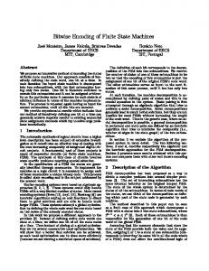
where • qs ∈ Q is the source state. • A guard g is a boolean expression generated by the following grammar g ::= true | false | e | ¬g | g ∨ g | g ∧ g (3) where e ∈ I. The evaluation of an event e is either true or false when the event is either present or absent. The operators ¬, ∨ and ∧ correspond to the boolean operators not, or and and, respectively. • An action lists a subset of the output events. I.e. an action a is a ::= nil | b (4) b ::= e | b, b (5) where e ∈ O and “,” distinguishes two events in the action. • qd ∈ Q is the destination state. In one reaction of the FSM, a subset of the events in I are present. One transition is triggered when its guard is true under the current input events. The FSM goes to the destination state of the triggered transition, and emits each output event in the action of the triggered transition, making these output events present. If the action is nil, it means that no output event is emitted. An action only lists the output events to be emitted, and thus all other output events are absent. We focus on deterministic and reactive FSMs. An FSM is deterministic if from any state there exists at most one triggered transition for the input events. An FSM is reactive if from any state there exists at least one triggered transition for the input events. To simplify notation and ensure that all our FSMs are reactive, every state is assumed to have an implicit self transition, i.e. going back to the same state and emitting no event, when there is no explicit outgoing transition to be triggered for the input events. A directed graph, called a state transition diagram, is popular for describing an FSM. As shown in figure 1, each elliptic node represents a state and each arc represents a transition. The arc without a source state points to the initial state, i.e. state α. Each transition links a source state with a destination state and is labeled by either “guard/ action” or “guard” (an abbreviation of “guard/nil”). Thus,
2.1. Hierarchy In a hierarchical FSM, a state may be refined into another FSM. Thus, we associate each state with a slave p that is p ::= nil | M (6) where M is an FSM. If p = nil, the state is an atomic state and is not refined; otherwise, the state is a hierarchical state. With respect to the slaves, the outside FSM is called the master. For example, we can let the state β in figure 1 be refined into another FSM but let the state α not be refined, as illustrated in figure 2. The input event set for the slave is a subset of the input event set of its master. Similarly, the output event set from the slave is a subset of the output event set of its master. The hierarchy semantics define how the slave reacts relative to the reaction of its master. A reasonable semantics defines one reaction of the hierarchical FSM as follows: if the current state is an atomic state, the hierarchical FSM behaves just like a basic FSM. If the current state is a hierarchical state, then first the corresponding slave reacts, and then the master reacts. Thus, two transitions are triggered, so two actions are taken. These two actions must be somehow merged into one. We take an output event to be present if the action of the master or any slave below it emits that output event. Since an action of the FSM does not explicitly set an event absent, no conflict is possible in this syntax. For example, if the hierarchical FSM of figure 2 is in state β and substate γ and input event a is present, the triggered action of the slave is “v” and the triggered action of the master is “u”. Thus, the output of the hierarchical FSM is “u, v” (both output events u and v are present).
¬a ∧ b ⁄ v α
β
Master
a ∨ ¬b ⁄ u
¬a ∧ b ⁄ v α
for figure 1, I = {a, b}, O = {u, v}, Q = {α, β}, q0 = α and T = {, , , }. Note that the last two transitions in T are implicit self transitions.
β
a⁄v γ
δ
Slave
a ∨ ¬b ⁄ u
b⁄v
Figure 1. A basic FSM.
Figure 2. A hierarchical FSM.
2.2. Heterogeneity Our hierarchical FSM is easily extended to support heterogeneity. The slave of a hierarchical state need not be an FSM. The key principle is that the slave must have a welldefined terminating computation that reacts to input events by (possibly) asserting output events. Therefore, the slave could be, for example, a Turing machine (that halts), a C procedure (that eventually returns), a dataflow graph (with a well-defined iteration), etc. It can even be concurrent. In this paper, we focus on combinations of FSMs with concurrency models. The hierarchy semantics is similarly defined as in previous section with one subtle modification: If the current state is a hierarchical state, then first the corresponding slave is invoked and then the master reacts. When the slave is invoked, it performs a determinate and finite operation, called an invocation of the slave, which reacts to input events and may assert output events. One invocation of a slave FSM is one reaction of the FSM.
2.3. Hierarchical entry and exit When a slave of a hierarchical state is invoked for the first time, unambiguously it will start from its initial conditions (e.g. the initial state for an FSM). When it is subsequently invoked, we may wish to reinitialize it or allow it to continue from the last known conditions. Thus, like in Statecharts [7], we support a transition entering a hierarchical state to be either history entry or initial entry. History entry permits the slave to resume computation from the final conditions of the last invocation. Initial entry starts the slave from the initial conditions like the first invocation. Under normal circumstances of a hierarchical FSM, if the current state is a hierarchical state, the corresponding slave is invoked prior to taking the transition. However, we may need to immediately interrupt before the slave is invoked in some situations. Thus, we support a transition exiting from a hierarchical state to be either preemptive or non-preemptive [10]. If a preemptive transition is triggered, the slave of the current state will not be invoked. Otherwise, for a non-preemptive transition, the slave is invoked normally.
2.
3.
4. 5. 6.
error and go to step 6. If exactly one is triggered, go to step 4. If the current state is a hierarchical state, perform one invocation of the slave. Depending on the entry type of the triggered transition in previous reaction, the slave either starts from the initial conditions or resumes from the final conditions of the last invocation. Check all non-preemptive transitions of the current state. If more than one is triggered, flag a non-deterministic error and go to step 6. If none is triggered, let the implicit self transition be triggered. Emit the output events in the action of the triggered transition. Enter the destination state of the triggered transition. I.e. let it become the current state for the next reaction. One reaction is complete.
3. Integration with concurrency domains In Ptolemy, we implement the proposed FSM model as a domain. A domain encapsulates a type of model of computation, and different domains are nested hierarchically to work together. Therefore, our objective is the hierarchical nesting of the FSM domain with concurrency domains, as shown in figure 3. We schematically illustrate the modules of the concurrency model with rectangular blocks and the states of the FSM model with elliptic nodes. The depth and order of the nesting is arbitrary. To achieve the goal, first we need for an FSM to be able to describe a module in a concurrency model. This can be done as long as that model provides a way to determine the input events and when a reaction should occur, and most Ptolemy domains have such properties. For example, in figure 4, two FSMs are embedded inside the modules of a concurrency model and, most interestingly, they are concurrent FSMs based on the concurrency semantics provided by that model.
2.4. Simulation algorithm To accommodate all the features discussed for the FSM, we come up with the following algorithm for simulating one reaction of the FSM: 1. Check all preemptive transitions of the current state. If more than one is triggered, flag a non-deterministic
Figure 3. Hierarchical nesting of FSMs with concurrency models.
a u
x v
a⁄v β
α
u⁄x v⁄y v b
u y
γ
δ
b⁄u
Figure 4. Two FSMs are embedded inside the modules of a concurrency model.
On the other hand, a state of an FSM needs to be able to be refined into a concurrency subsystem, as explained above in section 2.2. Among various existing Ptolemy concurrency domains, currently we focus on two of the more mature ones, the synchronous dataflow (SDF) and the discrete-event (DE) domains.
3.1. Synchronous dataflow Under the SDF [8] paradigm, a system consists of a set of blocks interconnected by directed arcs. The blocks represent computational functions that map input data into output data when they fire, and the arcs represent streams of data tokens implemented as first-in-first-out queues. Upon firing, a block consumes a fixed number of tokens from each input arc and produces a fixed number of tokens on each output arc. The number of tokens consumed and produced can be used to unambiguously define an iteration, or minimal set of firings that return the queues to their original size. Thus, the firing schedule for an iteration can be determined at compile time. To interact with the FSM domain, one invocation of an SDF graph is taken to be one iteration. A slight subtlety is that the absence of an event in FSM must appear explicitly as a token in SDF. A simple approach is to encode presence and absence using boolean-valued tokens. I.e. a true-valued token means the event present and a false-valued token means absent.
3.2. Discrete events The DE domain [3] carries a notion of global time that is known simultaneously throughout the system. An event occurs at a point in time. In a simulation of such a system, each event needs to carry a time stamp that indicates the time at which the event occurs. The time stamp of an event is typically generated by the block that produces the event,
and is determined by the time stamp of input events and the latency of the block. The DE simulator needs to maintain a global event queue that sorts the events by their time stamps, and chronologically processes each event by sending it to the appropriate block, which reacts to the event (fires). The notion of presence and absence of an event is the same in DE and FSM. However, in DE, every event needs a time stamp, something not provided by the FSM. We choose the semantics where the FSM appears to the DE as a zero-delay block. I.e. the event passed to the DE in a reaction of the FSM is assigned the same time stamp as the input event that triggers that reaction.
4. Implementation in Ptolemy 4.1. Ptolemy kernel 4.1.1. Star and Galaxy A system in Ptolemy is constructed by interconnecting blocks. Two types of blocks can be used for interconnection: the Star and the Galaxy. A Star is a fundamental (atomic) block, often containing code segments for simulation. A Galaxy is a block that internally contains Stars and possibly other Galaxies. In the FSM domain, we use a state transition diagram to describe a system. Each state inside the diagram is a fundamental block and thus is implemented as a Star. The diagram consisting of interconnected states is implemented as a Galaxy. 4.1.2. Wormhole In Ptolemy, different domains are intermixed hierarchically to work together. In other words, a domain needs to appear as a block inside another domain. Such a mechanism is a significant feature in Ptolemy and is called Wormhole. It encapsulates a subsystem specified in one domain within a system specified in another. The key idea of a Wormhole is that it must obey the semantics of outer domain at its boundary and the semantics of inner domain internally. We generalize the Wormhole mechanism in the FSM domain. Each state of an FSM may be associated with a Wormhole to encapsulate its slave subsystem. Thus, this subsystem can be defined in any domain, including FSM. 4.1.3. Scheduler Given a system consisting of a set of blocks in Ptolemy, a Scheduler manages the execution of a subsystem within
a wormhole. For the FSM domain, the Scheduler at each reaction simply follows the simulation algorithm described in section 2.4.
4.2. Graphical user interface A system in the FSM domain is described by a state transition diagram. The original visual interface to Ptolemy, called VEM, is not suitable for drawing the familiar bubble-and-arc diagram. A new visual editor is developed based on Tycho, a hierarchical syntax manager, which is part of the Ptolemy project. In addition to drawing the bubble-and-arc graph, users can click on a state to create or view its slave subsystem graph. After drawing the state transition diagram, users can further make an icon compatible with VEM and simulate it in Ptolemy.
5. Application example 5.1. System description A commonly used example for control-intensive software environments is the “reflex game” [1]. Our version of the reflex game is a two-player game (to introduce more concurrency). Each player has two buttons to press during the game: coin and go buttons for player 1; ready and stop buttons for player 2. Normal play proceeds as follows: 1. Player 1 presses coin to start the game. A status light turns blue. 2. When player 2 is ready, he presses ready, and the status light turns yellow. 3. When player 1 presses go, the status light turns green and player 2 presses stop as fast as he can. 4. The game ends, and the status light turns red. The game measures the reflex time of player 2 by reporting the time between the go and stop events. There are some situations where the game ends abnormally, and a “tilt” light flashes. These are: 1. After coin is pressed, player 2 does not press ready within L time units. 2. Player 2 presses stop before or at the same instant that player 1 presses go. 3. After player 1 presses go, player 2 does not press stop within L time units. One additional rule is that if player 1 does not press go within L time units after player 2 presses ready, then go is asserted by the system, and the game advances to wait for player 2 to press stop.
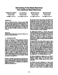
5.2. Ptolemy simulation Our realization of the reflex game in Ptolemy is shown in figure 5. To simulate the real-time behavior of the game, the DE domain is a good choice for the topmost level (a), modeling the environment of the game (including the players). In the DE model, the block Clock generates a sequence of clock ticks and then the block Synchronize synchronizes them with real time. The blocks Player1 and Player2 create the buttons (coin, go, ready and stop) for interacting with the players and the block Display creates the lights and reports the reflex time of player 2, as shown in (f). The block Reflex models the behavior of the game. At the next level of the hierarchy (b), inside the Reflex block, we have a two state FSM. The states are Game Off and Game On. Inside the Game On state, at level (c), we use a DE model consisting of the rules for the two players. These are interconnected with a zero-delay loop, and thus form an instantaneous dialog between the two players. At level (d), the two rules are refined into concurrent FSMs. Rule2 starts in the Wait Ready state, and when ready is asserted, emits a start event and transitions to the Wait Go state. This causes Rule1 to transition to the Wait state and emit a yellowLt event. The rest of the behavior at this level should now be evident from the figure. In several states, we need to count ticks from the clock to watch for time outs. This counting is a simple arithmetic computation that can be performed using the dataflow graph shown at level (e). This graph simply counts ticks, compares the count against a constant, and emits a timeout event when the threshold is exceeded.
6. Conclusions We have implemented an FSM domain in Ptolemy, and have successfully integrated it with two existing concurrency domains, the SDF and the DE domains. The FSM, SDF and DE models are best applicable in different situations. FSM is useful for describing sequential control functionality. SDF is ideal for computationintensive systems, such as most signal processing systems. DE is a natural way for specifying concurrent behavior of real-time systems. With these three models combined, a complex system can be systematically and modularly designed by choosing the best suited model for each distinct portion. Moreover, the mixed model is far more expressive than any one of the models alone. The implementation described here represents a fraction of what we hope to accomplish. In particular, the FSMs currently supported are “pure”, in the sense that
DE Clock Synchronize
FSM
(a)
Player1
time coin go ready stop
Reflex
redLt blueLt yellowLt greenLt normalExit flashTilt
Display
(b)
Player2
FSM DE time
Rule1 go
(d)
yellowLt
time go start
yellowLt
end ready stop time
start exit error greenLt
end
(c)
FSM
exit ready
stop
error
greenLt
Rule2
SDF time
(f) timeout
(e)
Figure 5. Our realization of the reflex game in Ptolemy.
events cannot carry values other than presence or absence. In many applications, non-boolean values are more useful. Also, the instantaneous dialog implemented in figure 5(c) would be better implemented using the synchronous/ reactive (SR) domain [5] in Ptolemy, since this would yield a description that could be more efficiently implemented in hardware or software. We have not yet integrated the SR domain with the FSM domain, although we have developed the semantics of the combination [6]. Finally, the reflex game example, which we chose in order to follow tradition in the HCFSM community, does not really illustrate the main advantages of our approach. A signal processing system would be a better illustration, where FSM subsystems are used for control logic and dataflow subsystems are used for numeric-intensive signal processing. We require valued FSMs to construct a suitably interesting example of this type.
Acknowledgments This research is part of the Ptolemy project, which is supported by the Defense Advanced Research Projects Agency (DARPA), the State of California MICRO program, and the following companies: The Alta Group of Cadence Design Systems, Hewlett Packard, Hitachi, Hughes Space and Communications, NEC, Philips, and Rockwell.
References [1]
R. Bernhard, G Berry, F. Boussinot, R. de Simone, G. Gonthier, A. Ressouche, J. P. Rigault, J. M. Tanzi, “Programming a Reflex Game in Esterel V3,” Rapport de Recherche No. 07/91, INRIA, Sophia-Antipolis, France, June, 1991.
[2]
J. T. Buck, S. Ha, E. A. Lee, and D. G. Messerschmitt, “Ptolemy: A Framework for Simulating and Prototyping Heterogeneous Systems,” Int. Journal of Computer Simulation, special issue on “Simulation Software Development,” vol. 4, pp. 155-182, April, 1994.
[3]
C. Cassandras, “Discrete Event Systems, Modeling and Performance Analysis,” Irwin, Homewood IL, 1993.
[4]
M. Chiodo, P. Giusto, H. Hsieh, A. Jurecska, L. Lavagno, A. Sangiovanni-Vincentelli, “Hardware-Software Codesign of Embedded Systems,” IEEE Micro, August 1994, pp.26-36.
[5]
S. A. Edwards, “The Specification and Execution of Heterogeneous Synchronous Reactive Systems,” Ph.D. dissertation, Memorandum UCB/ERL M97/31, Electronics Research Laboratory, University of California, Berkeley, California, May 1997.
[6]
A. Girault, B. Lee, and E. A. Lee, “A Preliminary Study of Hierarchical Finite State Machines with Multiple Concurrency Models,” Memorandum UCB/ERL M97/57, Electronics Research Laboratory, University of California, Berkeley, California, August 1997.
[7]
D. Harel, “Statecharts: A Visual Formalism for Complex Systems,” Sci. Comput. Program., vol 8, pp. 231-274, 1987.
[8]
E. A. Lee and D. G. Messerschmitt, “Static Scheduling of Synchronous Data Flow Programs for Digital Signal Processing,” IEEE Trans. on Computers, January, 1987.
[9]
F. Maraninchi, “Operational and compositional semantics of synchronous automaton compositions,” In Third International Conference on Concurrency Theory, volume 630 of Lecture Notes in Computer Science, pp. 550-564, Springer-Verlag, August 1992.
[10] M. von der Beeck, “A Comparison of Statecharts Variants,” In Formal Techniques in Real Time and Fault Tolerant Systems, volume 863 of Lecture Notes in Computer Science, pp. 128-148, Springer-Verlag, 1994.