Hierarchical Routing Architectures in Clustered 2D-Mesh Networks-on-Chip Markus Winter and Steffen Prusseit and Gerhard P. Fettweis
Technische Universit¨at Dresden, Vodafone Chair for Mobile Communications Systems Email:
[email protected]
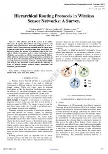
I. I NTRODUCTION Multi-Processor Systems-on-Chip are often seen as the suitable solution for the growing performance requirements in signal processing applications in terms of scalability, programmability and power consumption. The imposed interconnection problem in MPSoCs can be solved by packet-switched Networks-on-Chip (NoCs) [2], [4]. Many different realizations, e.g. AEthereal [7] or Nostrum [9], proved already their suitability for MPSoCs not only in simulation but also fabricated in silicon as working chip. All these realizations have in common to be small NoCs of at most one or two dozen modules attached to them. But since Moore’s Law is considered to held for another decade, the number of processors, ASIPs, memories, hardware accelerators and I/O systems integrated in one MPSoC will increase even more. The selection of a topology and routing algorithm suitable for such a large MPSoC impacts the overall system performance heavily. Unfortunately, the topologies usually used ([3]) have significant drawbacks. The star topology requires very large routers and multiplexers in the routers because of many attached modules. Performance of tree topology scales poorly with size because of the bottleneck at the top of the tree and fat tree requires significant hardware resources. Often 2D-mesh topology is considered to be a suitable choice. The hardware growth is linear with the number of modules in the MPSoC, it’s regular structure seems to fit very well to the chip floor-planning and the bisection bandwidth scales at least with the square root of the number of modules in the MPSoC. But, if we have a look at Fig. 1 we will find a significant drawback of the 2D-mesh: the achievable acceptance rate (explicitly the saturation point) decreases with the size of the NoC. While we can realize 45% in a 6x6 NoC at 16x16 we only can inject a packet in every 5th cycle at uniform traffic. At cluster traffic (see section IV) the behavior is similar though on higher level. In order to overcome the degradation of NoC performance, we require the 3rd dimension in some kind of hierarchy. But a fully connected fat tree would consume much to much area on the chip. The combination of 2D-mesh with other topologies or the introduction of 2D mesh clusters connected via another express 2D-
BE flit injection vs. acceptance rate for different mesh sizes
0.5 Acceptance rate
Abstract—The growing size of Multi-Processor Systems-on-Chip (MPSoC) calls for Networks-on-Chip (NoC) which scale with the increasing number of modules attached to them. Though current, 2D-mesh based NoCs scale linearly with the number of modules attached to them, their performance in terms of achievable throughput under typical traffic scenarios degrades. Clustered, hierarchical 2D-mesh NoCs may provide a solution to this problem by shortening the distance between two modules and adding more bandwidth. But it is merely researched what architectures with which parameters are suitable. In this paper we present and evaluate different realizations of clustered, hierarchical 2D-meshes, analyze their performance via cycle accurate simulations, determine their area consumption and derive recommendations which architecture is a suitable solution to the bandwidth degradation problem. Index Terms—Network-on-Chip, hierarchical routing, cluster, 2Dmesh.
0.4
6x6, uniform traffic 12x12, uniform traffic 16x16, uniform traffic 6x6, 3x3 cluster traffic 12x12, 3x3 cluster traffic
0.3 0.2 0.1 0 0
0.2
0.4 0.6 Injection rate
0.8
1
Fig. 1. NoC performance at best effort traffic in 2D-mesh NoC for different sizes of the NoC.
mesh one level above the original one can be a solution. [1], [10] and [5] proposed hierarchy and clustering with express ways in the NoCs. Besides other topologies they analyzed clusters of 4 modules which they connect via a bus or router in star topology. The clusters itself are connected with each other in 2D-mesh topology. Such architectures exploit the fact, that modules placed close together typically communicate more often with each other than with modules far away on the other side of the chip. Since [10] focuses more on the concrete implementation of this specific topology and [1], [5] analyze even more and different topologies, they miss to concentrate on hierarchical 2D-mesh topology in order to find the best tradeoff for specific design parameters when using hierarchical 2D-mesh topology and to identify performance trends. This paper will fill this gap. We analyze different realizations of hierarchical 2D-mesh topologies, compare their performance for different parameters, mesh and cluster sizes via simulations and provide area numbers for hardware realization of the architectures. Section 2 describes the basic, unclustered NoC architecture which we use as starting point for our research. Section 3 describes the clustered and hierarchical topologies and the associated routing details. Section 4 presents simulation results and section 5 hardware area numbers. Finally, section 6 concludes the paper. II. N ETWORK - ON -C HIP A RCHITECTURE Our NoC is formed of routers which are connected with each other and network interfaces (NI) by bidirectional links. So, every port of a router and an NI consists of an output and an input part. In the routers we use input queuing and wormhole routing for reduced buffer sizes in the routers. Flow control between the routers is realized via stall/go protocol. The routers use round robin arbitration between competing inputs for best effort traffic. Guaranteed service traffic for Qualityof-Service which our NoC supports, too, is left aside and will not be considered for the rest of this paper.
Header Burst (1 bit)
Source Source Target X Y X
Payload Target Y
Mode Address Data (4 Bit) (32 bit) (32 Bit)
Fig. 2. Structure of the flit used in the NoC. Note that all bits are transferred in parallel.
Template files of routers, modules, NoC Interfaces and so on in cycle accurate C++ and VerilogHDL are connected via a generation tool based on the NoC description in an XML-file. By this modular and flexible approach we can easily realize and analyze NoCs of different topologies, sizes or routing techniques. However, for the scope of this paper we will restrict ourselves to 2D-mesh and hierarchical, clustered 2D-mesh topology with deterministic xy-routing and for hierarchy slightly modified xy-routing, respectively. A flit is transmitted in one clock cycle across a link and requires 2 cycles per hop (1 cycle for link traversal into FIFO, 1 cycle for routing and putting out onto link). The flit contains the header with the target and source NI address information and the payload in parallel, Fig. 2. Bit width of target and source address are computed by the generation tool based on the mesh size, bit widths of the payload parts are parameterizable. An arbitrary number of flits (flow control digits), at least one, assemble a packet. If a packet consists of more than one flit this is indicated by a burst bit in the flit header.
a) Hierarchical 2D-mesh with Real Clusters
b) Hierarchical 2D-mesh with Additional Highway Connections
Fig. 3. 2 basic ways of clustering a 2D-mesh, exemplarily shown for 6x6 mesh with 3x3 clusters.
III. ROUTING IN H IERARCHICAL 2D-M ESH T OPOLOGIES Introducing hierarchy in a 2D-mesh can be done basically in two different ways: • Real cluster, Fig. 3a: The modules are organized into clusters which are completely separated from the other clusters on the low-level mesh. Each cluster is a 2D-mesh NoC on its own and has a connection to a router of the higher level mesh (’intercluster network’). So, if any module from one cluster wants to communicate with a module in another cluster, the flit must be routed to the connection to the intercluster network first, then across the 2nd level NoC and finally in the target cluster to the target NI. • Additional highway connections, Fig. 3b: The basic 2D-mesh is kept as it is. The higher level 2D-mesh network is not a necessity but an add-on. Flits which must travel long ways into other clusters can take the ’express’ way via the intercluster network. But if the target is close enough the flit can also take the way along the low-level mesh into another cluster. The routers decide whether a flit is forwarded to the intercluster network or whether it is kept in the low level mesh. For this, they compare the distance to the flit target in normal xy-routing and across the intercluster-network. Whatever is shorter will be taken. Additionally, it is made sure that a flit can only be forwarded to intercluster router if it has its origin in this cluster. Since a flit’s distance to the target never increases the decision whether to forward via intercluster network or via low level mesh is always the same in every router along the flit’s way. The intercluster network bundles the traffic coming from the clusters and transfers it to the other clusters. Therefore, a link in the intercluster network and also at the transition between lower and upper level mesh must provide a larger bandwidth than the links in the low level mesh. Higher frequency or additional links between the intercluster routers can realize this. We have decided for additional links since an increase of frequency by 2 or 3 in the intercluster NoC compared to the low-level mesh is very unlikely. Several of
Fig. 4. 4 possible data streams in the NoC with highways which can cause a deadlock.
such intercluster links in parallel incur the possibility of out of order transmission of flits. Since it is our goal to keep the order it is required to assign each link coming into the intercluster router from the low level mesh to exactly one of the parallel links in the intercluster network. The intercluster links are longer than links in the low level mesh. But we believe this will not be a significant problem. First, it is possible to route these intercluster links on high metal layer with reduced RC-delay. Second, new techniques like high-speed serialized, LVDS on-chip signaling will be available in near future and allow for long on-chip connections without degradation of frequency [8]. At the real cluster architecture, each cluster and the intercluster network use deterministic xy-Routing making the low level and high level mesh deadlock free. At the connection between the two levels the NoC is deadlock free, too, because there is exactly one router per cluster connecting the two levels and excluding the possibility of loops in the routing paths. The additional highway connections in opposite have the risk of deadlock even though the low level and the high level network use deadlock free xy-routing. The direct connections between routers from different clusters close the loop between router-1 in cluster1, intercluster router-1, intercluster router-2, router-2 in cluster-2 and back again to router-1 in cluster-1. Fig. 4 shows 4 possible data streams which can block each other if the FIFOs in the routers are full: red waits for blue, blue waits for green, green waits for yellow and yellow for red. In order to overcome this deadlock it is necessary to avoid such cycles. We can break the cycle by moving the connection to the intercluster network to a corner of the cluster, Fig. 5a. The turn from south and west to intercluster cannot happen here because flits only can be routed to the intercluster router of their
a)
BE flit injection vs. acceptance rate for different cluster sizes (12x12 mesh, uniform traffic)
b)
Acceptance rate
0.6 0.5 0.4 0.3 0.2
central, cl=2x2 central, cl=3x3 central, cl=4x4 corner, cl=2x2 corner, cl=3x3 corner, cl=4x4 realCl, cl=2x2 realCl, cl=3x3 realCl, cl=4x4 no Hierarchy
0.1 0 0
Bypass link Fig. 5. 2 realizations of a deadlock free 2D-mesh with highways: a) Highway connections at cluster corner (corner router). The red arrows indicate turns which are not possible in this system. b) Highway connections at cluster center via bypass links (central router)
Fig. 6.
0.8 0.7 0.6 Acceptance rate
own cluster, breaking up the loop. According to the turn model [6] corner router topology with xy-routing at each level is deadlock free. Another possibility of deadlock avoidance is the addition of bypass links in the low level 2D-mesh, Fig. 5b. When the flit is injected into the NoC the very first router decides whether to forward the flit via low level or intercluster network. If it is decided to be routed along the intercluster mesh, the flit is forwarded to the intercluster router via the bypass links which are additional connections at the routers. Otherwise the flit is transmitted via the normal links in the low level mesh. By that it is ensured that the loop causing a deadlock is avoided because the links to the intercluster router and the low level 2D-mesh are physically separated. In order to distribute the traffic evenly onto the bypass links, they are arranged in a special way within the 2Dmesh, Fig. 5b.
0.2
0.5 0.4 0.3 0.2
0.4 0.6 Injection rate
0.8
1
Performance at different cluster sizes.
BE flit injection vs. acceptance rate for different cluster sizes (12x12 mesh, cluster traffic 50%) central, cl=2x2 central, cl=3x3 central, cl=4x4 corner, cl=2x2 corner, cl=3x3 corner, cl=4x4 realCl, cl=2x2 realCl, cl=3x3 realCl, cl=4x4 no Hierarchy, cl=2x2 no Hierarchy, cl=3x3 no Hierarchy, cl=4x4
0.1 0 0
0.2
Fig. 7.
0.4 0.6 Injection rate
0.8
1
Performance at different cluster sizes.
IV. S IMULATION R ESULTS In order to evaluate the performance of the different architectures we simulated meshes of size 6x6, 8x8, 10x10 and 12x12 with cluster sizes of 2x2, 3x3, 4x4 and with 1, 2, 3 and 4 intercluster links. We simulated two traffic scenarios: • •
uniformly distributed cluster traffic: 50% within the cluster, 50% uniformly distributed in the rest of the NoC.
The simulations realized POISSON streams and were run 500.000 cycles where the upper and lower 10% of simulation were ignored in order to avoid transient effects. Due to lack of space here, we only show the results for 12x12 NoC since the hierarchical, clustered mesh architectures are targeted at large NoCs. In Fig. 6 and Fig. 7 we compare the performance in terms of throughput via acceptance rate at different cluster sizes when using the different NoC architectures at their best performance (highest number of intercluster links). At the graph with cluster traffic, there are 3 curves for NoC without hierarchy. Though no clusters in the architecture, the traffic has clustered character. In order to be more comparable with the hierachical architectures the traffic cluster sizes are adapted to the architectural cluster sizes. We find, as expected, that the central router architecture with highway connections (red) performs best at each cluster size and brings performance gains of up to 20 or 30%, though it must be stated that at cluster size of 4x4 the gain with respect to unclustered NoC (black) is only marginally. Corner and real cluster architectures
are still able to handle up to 10% more traffic at small cluster sizes. But they perform even worse than an unclustered NoC at cluster sizes of 3x3 or 4x4 (and beyond). This results from the long distance which flits have to travel to the intercluster router, though the magnitude of the performance loss is surprisingly high. Additionally, at real cluster the missing direct connections at cluster boundaries causes the very bad performance - at uniform and cluster traffic. At this point it must be mentioned, the real cluster architecture performs worse than unclustered architecture at NoC sizes of 6x6 even at a small cluster size of 2x2. So, it does not make sense to use real cluster architectures at NoCs of 6x6 or below. After we found, that only cluster sizes of 2x2, at most 3x3 make sense, we want to evaluate the number of intercluster links required between two routers of the intercluster network in one direction. The more intercluster links the more traffic the intercluster network can absorb. On the other side there should be as less links as possible because with every required link the are consumption grows. In Fig. 8 and Fig. 9 we compare the intercluster link quantity for a 12x12 mesh with 2x2 clusters for the real cluster and central router with highway connections. We find, one intercluster link is not sufficient here. Instead at least two links must be available for each direction in the intercluster network. For real cluster architecture it should be three links in order to compete with the central router architecture because in opposite to central router at real cluster all intercluster traffic must travel along the intercluster network.
BE flit injection vs. acceptance rate for different numbers of intercluster links (12x12 mesh, 2x2 clusters, uniform traffic)
Acceptance rate
0.5 0.4 0.3
central, ICLQ=1 central, ICLQ=2 central, ICLQ=3 central, ICLQ=4 realCl, ICLQ=1 realCl, ICLQ=2 realCl, ICLQ=3 realCl, ICLQ=4 no Hierarchy
TABLE I A REA SUMMARY OF THE WHOLE N O C FOR DIFFERENT SIZES OF MESHES AND CLUSTER (’ MESH SIZE - CLUSTER SIZE ’). A LL SIZES IN K NAND. 12x12 - cluster 2x2
0.2
12x12 - cluster3x3
#intercluster links
2
3
2
3
No hierarchy
2227
2227
2227
2227 2562
Real cluster
2649
3400
2248
Corner router
3627
4405
2941
3255
Central router
4274
5001
3336
3639
0.1 0 0
Fig. 8.
0.2
0.4 0.6 Injection rate
0.8
1
Performance at different numbers of intercluster links.
Acceptance rate
BE flit injection vs. acceptance rate for different numbers of intercluster links (12x12 mesh, 2x2 clusters, cluster traffic 50%) 0.8 central, ICLQ=1 central, ICLQ=2 0.7 central, ICLQ=3 central, ICLQ=4 0.6 realCl, ICLQ=1 realCl, ICLQ=2 0.5 realCl, ICLQ=3 0.4 realCl, ICLQ=4 no Hierarchy 0.3 0.2 0.1 0 0
Fig. 9.
0.2
0.4 0.6 Injection rate
0.8
1
Performance at different numbers of intercluster links.
V. A REA R ESULTS The different routing schemes were realized in VerilogHDL, too, in order to verify the cycle accurate C++ model and to gain area numbers required for realization of hierarchical routing in clustered 2D-mesh NoCs. The routers were synthesized for a FIFO size of 4 entries with Synopsys Design Compiler for FARADAY’s 130 nm UMC library with a target frequency of 200 MHz which every of the routers achieved. The flit size was set to 68 bits of payload (32+32+4) and the mesh size dependent header width is 17 bit (4*4 + 1) for 12x12 meshes which we will show here. Table I shows the area consumption of the NoC contributed by the routers. As expected, the area consumed in hierarchical, clustered 2D-mesh NoCs is significantly larger than in pure 2Dmesh topology. Solely, the real cluster architecture is able to keep up with the growth of the pure 2D-mesh. The size of the powerful central router architecture and of the corner architecture in opposite grow significantly and at most doubles the area requirements. It is, therefore, questionable whether the performance gain can justify the use of central or corner architecture. Optimizations, e.g. in the FIFO sizes or by usage of dedicated Synopsys DesignWare components, might reduce the area but probably cannot break it down to the area consumption of pure 2D-mesh or optimized real cluster systems. VI. C ONCLUSION It was the goal of this paper to evaluate and analyze the parameter space for clustered, hierarchical 2D-mesh architectures as they were
introduced in [1], [5], [10]. We based completely on 2D-meshes and derived real cluster NoCs and 2D-meshes with additional highway connections as corner and central cluster. All architectures were deadlock free and retained the order of the transmitted flits. We could achieve significant performance improvements of up to 30% more traffic acceptance by the NoC. Especially, the highway architectures were able to handle much more traffic than pure 2Dmesh topology raising the saturation point in the NoC under uniform and cluster traffic model. As expected, we found: the smaller the cluster size, the more can be achieved by hierarchical NoCs. But surprisingly, we found cluster sizes of 4x4 or beyond have negative impact on the NoC performance compared to pure 2D-mesh. So we can state, either use clusters smaller than 4x4 or leave hierarchical clusters out. However, the huge area overhead which hierarchical routing with highway connections incurs redirects us back to real cluster routing. If we restrict to small clusters (2x2) we can achieve considerable performance improvements with moderate area overhead. By replacing the small 2x2 2D-mesh clusters by a star topology like in [5] we probably can reduce the area consumption of real cluster architecture siginificantly. So, our simulations and hardware analysis approve [5] who intuitively found one of the most suitable topology and architecture for hierarchical 2D-meshes. R EFERENCES [1] J. Balfour and W. Dally. Design tradeoffs for tiled cmp on-chip networks. In Proc. of 20th Int. Conf. on Supercomputing, pages 187–189, 2006. [2] L. Benini and G. Micheli. Networks on Chips: A New SoC Paradigm. Computer, 45(1):70–78, January 2002. [3] T. Bjerregaard and S. Mahadevan. A survey of research and practices of network-on-chip. ACM Computing Surveys (CSUR), 38(1):414–421, 2006. [4] W. Dally and B. Towles. Route Packets, Not Wires: On-Chip Interconnection Networks. In Proc. of DAC, pages 84–89, June 2001. [5] F. Gilabert, D. Ludovici, S. Medardoni, D. Bertozzi, L. Benini, and G. Gaydadjiev. Designing regular network-on-chip topologies under technology, architecture and software constraints. In Proc. of INt. Conf. on Complex, Intelligent and Software Intensive Systems, pages 681–687, March 2009. [6] C. Glass and L. Ni. The turn model for adaptive routing. 41(5):874–902, September 1994. [7] K. Goossens, J. Dielissen, and A. Radulescu. AEthereal Network on Chip: Concepts, Architectures and Implementations. IEEE Design and Test of Computers, 22(5):21–31, September-October 2005. [8] L. Kangmin, S. Lee, and H. Yoo. Silent: serialized low energy transmission coding for on-chip interconnection networks. In Proc. of Int. Conf. on Computer Aided Design (ICCAD), pages 448–451, January 2005. [9] M. Millberg and et al. Guaranteed Bandwidth using Looped Containers in Temporally Disjoint Networks within the Nostrum Network on Chip. In Proc. of DATE, pages 890–895, February 2004. [10] C. Puttmann, J. Niemann, M. Porrmann, and U. Ruckert. Giganoc - a hierarchical network-on-chip for scalable chip-multiprocessors. In Proc. of Euromicro Conf. on DSD, pages 495–502, August 2007.