Hazard and Operability Studies (HAZOP) [2], Failure Mode and Effects Analysis .... At plant level such flow diagrams can be derived, for example, from.
th
In Proceedings of SAFECOMP ’99, 18 International Conference on Computer Safety, Reliability and Security, Toulouse France, Lecture Notes in Computer Science, 1698:139-152, Springer Verlag, 1999. It is also among the ten papers selected by the programme committee for publication in a special issue of the Journal of Reliability Engineering and System Safety (in print)
Hierarchically Performed Hazard Origin and Propagation Studies Yiannis Papadopoulos, John A. McDermid, Department of Computer Science, University of York, YO10 5DD, UK {yiannis, jam}@cs.york.ac.uk
Abstract. This paper introduces a new method for safety analysis called HiPHOPS (Hierarchically Performed Hazard Origin and Propagation Studies). HiP-HOPS originates from a number of classical techniques such as Functional Failure Analysis, Failure Mode and Effects Analysis and Fault Tree Analysis. However, it extends, automates and integrates these techniques in order to address some of the problems currently encountered in complex safety assessments. The method enables integrated assessment of a complex system from the functional level through to the low level of component failure modes. It mechanises and simplifies a large part of the analysis, the development of fault trees, and can guarantee the consistency of results. HiP-HOPS is currently supported by a tool called the Safety Argument Manager (SAM). In this paper we introduce the method and we show how it has helped us analyse and improve the safety of a distributed brake-by-wire system for cars.
1. Introduction Classical safety analysis techniques such as Functional Failure Analysis (FFA) [1], Hazard and Operability Studies (HAZOP) [2], Failure Mode and Effects Analysis (FMEA) [3] and Fault Tree Analysis (FTA) [4] have demonstrated their value in a variety of contexts over the years, and they are still widely practised by safety engineers. These safety studies still form the spinal element of the safety case, and provide a frame for the interpretation of the results from other, more localised, verification activities such as testing and the application of formal methods. As the complexity of modern programmable electronic systems increases, however, the application of classical techniques is becoming increasingly more problematic. The first problem that can be observed is inconsistencies in the results from the various safety studies of the system which mainly arise from the selective and fragmented use of different methods at different stages of the design lifecycle. Classical techniques assume different design representations which reflect different levels of abstraction in the system design. While, for example, FFA requires only abstract functional descriptions, HAZOP and FMEA require architectural designs of increasing detail and complexity. The problem is that these different design representations are often inconsistent. One of the causes of inconsistency is that different notations are employed at different stages of the lifecycle. Perhaps more importantly, abstract designs are not always kept updated, and they don’t reflect changes made in lower level designs. Inevitably, the analyses that are based on inconsistent designs become themselves inconsistent. One significant conclusion that
in our view can be drawn from this discussion is that if we wish to address the problem of inconsistencies in the analyses then we must find ways to guarantee the consistency of the design as this evolves in the course of the lifecycle. A second problem in classical safety analysis is the difficulty in relating the results of the various safety studies between them and back to the high-level functional failure analysis. The problem here lies in the difficulty that analysts encounter in drawing a coherent and complete picture of how low level component failures contribute to hazardous system malfunctions. Although fault trees are built for this purpose, the traditional process of constructing these fault trees relies almost exclusively on expert knowledge, and lacks a systematic or structured algorithm which the analyst can apply on a system model in order to derive the tree. In complex systems this process becomes tedious, time consuming and error prone, and the resultant fault trees are large, but more importantly, difficult to interpret and verify. In consequence, safety analyses are in practice not only voluminous but also fragmented and inconsistent. Such analyses, however, are difficult to interpret and do not always provide a useful resource in the design of the system. But, is it not precisely the aim of safety analysis to improve the system design? And does the fragmentation of classical techniques not compromise this aim? To address this and some of the other questions that we have raised in this section, we propose a new method for safety analysis which, we believe, improves classical safety analysis techniques. The new method is called Hierarchically Performed Hazard Origin and Propagation Studies (HiP-HOPS). The method enables the integrated assessment of a hierarchically described complex system from the functional level through to the low level of component failure modes. To ensure the transferability of the practical experience that classical analyses incorporate, we have founded the new method on a number of well-established techniques such as FFA, FMEA and FTA. At the same time we have modifed, automated and integrated these techniques to overcome some of the difficulties that we have already discussed. The method mechanises and simplifies a large and traditionally problematic part of the analysis, the development of fault trees. It also integrates classical hardware safety analysis with software hazard analysis and guarantees the consistency of the results from the assessment. HiP-HOPS draws from previous work on new safety assessment techniques, more specifically, the work on the Failure Propagation and Transformation Notation [5] and a technique called Failure Logic Analysis for System Hierarchies [6]. In this paper we introduce the method and demonstrate its application on a distributed programmable electronic braking system for cars. This system is a research prototype that has been developed in the context of a European Commission funded project called Time Triggered Architectures (TTA-ESPRIT Project 23396). The system provides a design concept for possible future brake by wire applications in the automotive industry. It is implemented over a network of six programmable electronic nodes which communicate using TTP/C [7], a Time Triggered communication Protocol. Two of these nodes, the pedal nodes, are physically located near the braking pedal. Their function is to continuously read and broadcast the braking demand on two replicated busses. On the receiving end of communication, there are four wheel nodes which calculate and apply the final braking pressure on the four wheels of the car.
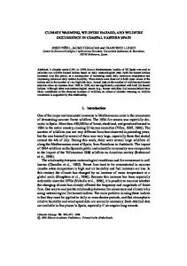
2. HiP-HOPS In HiP-HOPS all safety studies are performed on a consistent hierarchical model of the system. The method places constraints on the notations used, and introduces some additional notation for describing levels of design. The notation allows complex systems to be modelled as system hierarchies (Fig. 1). At each level of the system hierarchy, flow diagrams are used to describe the operation of the system and its subsystems. At plant level such flow diagrams can be derived, for example, from engineering schematics or piping and instrumentation diagrams. At lower levels, data flow diagrams (e.g. MASCOT diagrams) can be used to describe the design of software and hardware components. 2.1 Functional Failure Analysis The safety analysis process starts with exploratory functional failure analysis (FFA) of a conceptual design of the system. At this stage an abstract functional model of the system is used in order to identify single and plausible combinations of multiple functional failures and assess their effects and criticality. The functional model is constructed as a functional block diagram which identifies the system functions and their dependencies in terms of material and energy flows or data. Each function in this model is systematically examined for potential failure modes is a number of failure classes which include the loss of function, the unintended delivery of function and malfunctions such as early or late deployment. For each such failure the analyst has to determine the effects, criticality and the potential for detection and recovery. Once we have identified all the single functional failures, we can then identify and list plausible combinations of multiple failures and, in a similar way, examine the effects and criticality of such failures. System Design
Safety Analysis
FFA
*
Fault Tree Synthesis Algorithm
Mechanically generated fault trees which show how functional failures that we have identified in the FFA arise from lowlevel component failure modes that we have identified in the IF-FMEAs
Loss of bra ke. Caused by a actuator failures OR an om issi on number of of 0
-
0
_buffer_stuc k_at_ - 0 8e-006
0
cuit_to_P S 9e-006
_failure
cally_stuc Control P ressure stuck k 0. Caused by at m em ory stuck at 0 controller 3e-007 4e-007 OR 0
CR.controller_me mor y_ stuc k_at_ 0 -
Omission of pressure. Caused by control afailure of the controller 0
I1 -
-
3e-006
** IF-FMEAs IF-FMEAs
0
5e-006
0
I2 -
Pressure feedback stuc k at 0. Caused by value an um ber of sensor failures 0
0
Default braking Om ission of t he Stuck at 0. Causedbraking value pressure Default Input Caused by a failure by setpoint. Generator of 0 0
-
P ressure setpoint at 0. Caused by Stuck m emoryof the failure input
mecha nical ly_stmemory_b uc uffer_stuc k k _a 1e-007
5e-006
P ressure feedbackPressure feedback is below t he exceeds the value value m inimLimit. valid um Caused valid maximum by lim it . Caused by a a 0 0
0
_ms g 0.0005
0
hort_circuit_to_GN D 9e-007
pen_l ine
0
hort_circuit_to_P Omission of the S braking default set-point. Caused pressure 8e-007 8e-006 by -
0
0 -
0.0005
IF-FMEAs**
-
-
0.0009
0
e_msg -
re_ms g
0
*
0.0004
g 0
0
FFA: Functional Failure Analysis (Analysis of the failure behaviour of the system at the functional level) IF-FMEAs: Interface Focused FMEAs (Analyses of the local failure behaviour of the system components)
**
Fig. 1. Overview of Design and Safety Analysis in HiP-HOPS
The results of this study are recorded in a tabular form and provide early in the design process a comprehensive picture of the ways that the system can fail. The first objective of the study is to identify critical functional failures of the system, in other words functional losses or malfunctions which lead to severe or catastrophic effects. The second objective is to identify, and remove early any avoidable dependencies between different functions that can lead to common mode failures, in other words conditions where more than one function fails as a result of a single initiating event.
2.2 Assessment of Failure at Component Level As the design decomposition and the refinement of the hierarchical model proceed, we identify basic hardware and software components. The failure behaviour of these components is analysed using an extension of FMEA. Traditional FMEA examines the origins of failure within the component itself. In other words, it examines the failure behaviour of the component considering only internal malfunctions (possibly caused by the environment). The function of a component in the failure domain, however, is much more complicated. A component does not only generate failure events. It can also detect (or not) and respond (or not) to failure events generated by other components which interface to the component inputs. A component, for example, may detect disturbances of its input parameters, e.g. the absence of a power signal, or a value that is out of range. In turn, the component can mitigate the propagation of such failure events. It may, for example, replace a detected invalid input value with a correct default value. It can also fail to detect input failures and propagate these failures to other components. Finally it may transform a certain input failure event, to a different type of output failure. An example of this is a component which detects a timing failure to one of its inputs and, in response, fails silent (e.g. the TTP/C protocol communication controller [9]). To capture these additional aspects of the behaviour of the component, we propose an extension of FMEA, called IF-FMEA (Interface Focused-FMEA). IF-FMEA is a tabular technique. It can be used in a similar way to traditional FMEA in order to examine component failure modes caused by internal malfunctions. Beyond that however, the method provides a systematic way to examine the detection, mitigation and propagation of failure across the component input and output interfaces. The method is applied to each component and generates a failure model (represented as a table) for the component under examination. An IF-FMEA table provides a list of component failures modes as they can be observed at the component outputs. For each such failure the analysis determines the causes as a logical combination of un-handled internal malfunctions and un-handled deviations of the component inputs. Beyond hardware safety analysis, IF-FMEA can also be used for software hazard analysis. An example of a software IF-FMEA is given in Table 1. The table presents the IF-FMEA of the pedal task which is located on the pedal node of the brake by wire system.
Table 1. Excerpt of IF-FMEA of PEDAL task Output Failure Mode
Description of output failure
Input Deviation Logic
Component Malfunction Logic
λ (f/h)
O-PEDAL1. Driver_msg
Omission of PEDAL1 output (braking demand). It can be caused by task malfunction or out of range failures of both pedal sensors
(V>max-PS1.value | Vmax-PS2.value | Vε, k
then it is considered invalid and is discarded. The model of a software task that uses such a mechanism is illustrated in Figure 6. The task performs peak detection on the input value (m). When the input value does not violate the peak detection criterion, it is copied to the task output (o). In the opposite case the output carries the average of the last k valid values (a). During the IF-FMEA analysis of the task and as we systematically examine the task output (o) for potential failure modes, we will have to consider the possibility of the output being stuck at a certain value. Part of the examination process is to identify deviations of the input (m) that can cause the stuck at failure at the output.
m
a=(i=1Σ vmi)/k;
o
measurement
If |m-a|≤ε o=m else o=a;
output
k
Fig. 6. Simplified Model of the Peak Detection and Removal Task
An obvious case of such a deviation is the omission of input. For as long there is an omission of input, the output will be stuck at a value defined by the average of the k last valid measurements. More importantly the stuck at failure may persist following the end of a temporary omission. Indeed, if the omission is long enough to create a deviation between the restored measurement and the last valid average which is greater than ε, then all new measurements will be discarded as invalid. Let us now assume that the task is part of the wheel node implementation. The task input is the pedal message arriving through the bus and the task output is the braking pressure applied to the wheel. Our analysis has shown that if there is a temporary omission of the pedal message at the early stages of braking (e.g. due to electromagnetic interference), the output might be permanently stuck at zero or at a low braking value which will cause a failure to brake. Once we have determined the failure behaviour of all the components in the hierarchical model, we can then proceed to the final stage of the analysis where we determine the structure of the fault propagation process in the system. At this stage, we determine how the functional failures that we have identified in the exploratory FFA arise from combinations of the low-level component failure modes that we have identified in the IF-FMEAs. As we have explained, in HiP-HOPS this is achieved mechanically with the aid of a systematic algorithm for the synthesis of fault trees. In the course of the BBW case study we have used the method and the tool to mechanically generate, regenerate and evaluate a number of such fault trees. Figure 7 illustrates, for example, the fault tree that SAM has synthesised for the event “loss of wheel braking”. Using assumptions about component failure rates that we have made in the IF-FMEAS, SAM has calculated the likelihood of the top event. As a result the design of the system was changed since we have last analysed it.
Fig. 7. Distant view of the fault tree that SAM generated for the event “Loss of wheel braking”
For those reasons the number that we have calculated does not provide a realistic failure rate prediction for the brake by wire system. In our view though, it indicates that HiP-HOPS can rationalise the development and maintenance of large fault trees, and, in that sense, can alleviate some of the problems currently encountered in the quantitative aspects of complex safety assessment. It is equally important to point out that the synthesis algorithm cannot generate such fault trees if there are inconsistencies in the hierarchical model or between the analyses. In such cases the algorithm simply points out the inconsistencies. Synthesised fault trees, therefore, link in a consistent manner the results from the various analyses to each other and back to the high-level functional failure analysis, and hence guarantee the consistency of the safety case.
4. Conclusions Safety analysis techniques are evolving to deal with the complexity of modern safety critical systems, for example via the use of functional approaches to safety assessment. However, two significant problems still arise in the assessment of complex systems using classical safety analysis techniques: inconsistencies in the results from the different safety studies of the system and a difficulty in relating the various analyses between them and back to the functional hazard assessment. In this paper, we have shown one way to address these problems by extending, automating and integrating a number of classical techniques into a new method for safety analysis called HiP-HOPS. We have described the method and demonstrated its application on a distributed brake by wire system for cars. In HiP-HOPS, the analysis of a complex system starts at the functional level and proceeds all the way down to the low levels of the hardware and software implementation. The method assumes a consistent hierarchical model of the system and can guarantee the consistency of results. HiP-HOPS integrates hardware safety analysis with software hazard analysis. It also introduces a new algorithm for the synthesis of fault trees which mechanises and simplifies a large part of the analysis (the development of fault trees), and can help to address some of the difficulties encountered in manual fault tree analysis. The method has helped us to improve the failure detection and recovery mechanisms of the brake by wire system. It has also helped us identify subtle errors in the design of certain software algorithms. Our limited experience from the application of the new method has been very positive. More work is, however, required to further evaluate the practicability of the method, and to determine its potential and limitations. Currently, for example, HiPHOPS is only suitable for the analysis of complex electromechanical systems which have limited interaction with human operators. But, would it be possible to apply the method on more interactive systems where operator errors contribute significantly to the failure of the system? This is one of the questions that we will attempt to address in the near future.
Acknowledgements The authors wish to thank Pete Fenelon and Giuseppe Mauri from the University of York. Their earlier work on new techniques for safety assessment [5][6] has nfluenced several of the principles that underlie HiP-HOPS. We also wish to thank all our colleagues at the Technological University of Vienna and Daimler Chrysler Research in Berlin who have helped us understand the technology involved in the TTA project. This work would not have been possible without the infrastructure that Pete Kirkham and Steve Wilson have developed in SAM and upon which the algorithms of HiP-HOPS have been implemented. Special thanks also go to Ralph Sasse from Daimler Chrysler who has provided us with an insight to the mechanics of brake by wire systems.
References [1]Society of Automotive Engineers, ARP-4761:Aerospace Recommended Practice: Guidelines and Methods for Conducting the Safety Assessment Process on Civil Airborne Systems and th Equipment, 12 edition, SAE, 400 Commonwealth Drive Warrendale PA United States, 1996. [2]Kletz T., HAZOP and HAZAN: Identifying and Assessing Process Industry Standards, 3rd Edition, Hemisphere Publishers; ISBN: 1-560-32276-4, 1992. [3]Villemeur A., Reliability, Availability Maintainability and Safety Assessment, John Willey and Sons , ISBN 0-471-93048-2, 1992. [4]Vesely W.E., et al, Fault Tree Handbook, US Nuclear Regulatory Committee Report NUREG-0492, pages X.15-18, US NRC Washington DC United States, 1981. [5]Fenelon P., McDermid J.A., Nicholson M. and Pumfrey D.J, Towards Integrated Safety Analysis and Design, ACM Applied Computing Review, 2(1):21-32, 1994. [6]Mauri G., McDermid J.A., Papadopoulos Y., Extension of Hazard and Safety Analysis Techniques to Address Problems of Hierarchical Scale, IEE Colloquium on Systems Engineering of Aerospace Projects, London, IEE Digest No: 98/249, pages. 4.1/4.6, IEE, 1998. [7]Kopetz H., Real-time Systems, Design Principles for Distributed Embedded Applications, ISBN 0-7923-9894-77, Kluwer Academic Publishers, 1997. [8]McDermid J.A., Support for Safety cases and Safety Arguments Using SAM, Reliability Engineering and System Safety, 43:111-127, Elsevier Science, 1994. [9]International Electrotechnical Commission 65A/179-185, IEC-61508: Functional Safety of Electrical/Electronic/Programmable Electronic Safety-related Systems, IEC, 3 rue de Varembé CH 1211 Geneva Switzerland, 1997. [10]Kopetz H., Grünsteidl G., TTP: A Protocol for Fault Tolerant Real-time Systems, IEEE Computer, 27(1):14-23, 1994.