This article has been accepted for publication in a future issue of this journal, but has not been fully edited. Content may change prior to final publication. Citation information: DOI 10.1109/LED.2018.2795039, IEEE Electron Device Letters
High-density NAND-like spin transfer torque memory with spin orbit torque erase operation Zhaohao Wang, Member, IEEE, Lei Zhang, Mengxing Wang, Zilu Wang, Daoqian Zhu, Youguang Zhang and Weisheng Zhao, Senior Member, IEEE Abstract—We present a NAND-like spintronics memory (NAND-SPIN) device for high-density non-volatile memory applications. Fast erasing and programming of magnetic tunnel junction (MTJ) are implemented with two unidirectional currents generating spin orbit torque (SOT) and spin transfer torque (STT), respectively. The asymmetric switching drawback of STT mechanism can be definitively overcome as only anti-parallel to parallel operation happens for NAND-SPIN programming, which allows lower switching current, smaller access transistor and reduced maximum write voltage across the MTJ. By sharing the SOT-induced erase operation in a nanowire, the area overhead due to the three-terminal structure can be also eliminated. Simulation results show that NAND-SPIN can achieve 3~5X reduction in write energy compared to STT-MRAM, and 2~4X less bit-cell area than SOT-MRAM at 28 nm node. Index Terms—Magnetoresistive random access memory, spin orbit torque, spin transfer torque, high density
M
I. INTRODUCTION
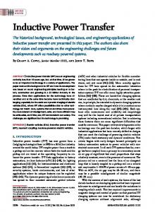
random access memory (MRAM) using spin transfer torque magnetic tunnel junction (STT-MTJ) has been widely considered a promising candidate for the future universal memory owing to its non-volatility, high endurance, fast operation, CMOS process compatibility, etc [1]. Nevertheless, the performance of the STT-MRAM is deteriorated by the asymmetry of write operation between writing ‘1’ and ‘0’. On the one hand, the critical current for parallel-to-antiparallel (P-to-AP) switching is larger than that for AP-to-P switching due to asymmetrical STT efficiency [2]. On the other hand, for the one-transistor-one-MTJ (1T-1MTJ) bit-cell shown in Fig. 1(a), while the current flows from the source line (SL) to bit line (BL), the drivability of the access transistor is degraded due to smaller gate-source bias, which is called source degeneration. Therefore, the access transistor has to be sufficiently large to meet the requirement of worse case of the write operations. However, for the other case, the access transistor is overlarge to induce undesirable high current and AGNETORESISTIVE
This work was supported in part by National Natural Science Foundation of China (Grant 61704005, 61571023, 61627813), the International Collaboration Project B16001, and the National Key Technology Program of China 2017ZX01032101. The authors are with Fert Beijing Research Institute, School of Electrical and Information Engineering, BDBC, Beihang University, China. (e-mail:
[email protected]). Z. Wang, L. Zhang and M. Wang contributed equally.
Fig. 1. (a) Bit-cell of the 1T-1MTJ STT-MRAM. Here the source degeneration of the access transistor causes asymmetric write operation. (b) Bit-cell of the standard 2-transistor SOT-MRAM and a schematic layout (CMOS part).
impaired reliability of the tunnel barrier. In addition, the STT switching speed is limited by an intrinsic incubation delay. This issue is addressed by exploiting spin orbit torque (SOT) which is an emerging mechanism for fast magnetization switching [3]-[5]. However, a standard SOT-MRAM bit-cell contains two access transistors as Fig. 1(b), leading to the difficulty in improving the integration density. Note that the two access transistors need to have the same width due to the layout limitation (see the bottom inset of Fig. 1(b)), even if the read current is much smaller than the write current [6]. Besides, the source degeneration problem is still unresolved in the SOT-MRAM. To overcome the aforementioned drawbacks of both STT-MRAM and SOT-MRAM, in this letter we propose a novel spintronics memory with NAND-like architecture (hence called NAND-SPIN). The data is written into the NAND-SPIN by applying two unidirectional currents, which perform a SOT-induced erasing and a STT-driven programing, respectively. NAND-SPIN allows low write energy, small voltage drop across the MTJ, and high integration density. II. NAND-SPIN STRUCTURE AND OPERATION As shown in Fig. 2(a), similar to NAND-Flash memory, the NAND-SPIN array is organized physically in strings while logically in pages and blocks [7]. A NAND-SPIN string contains MTJs which can be integrated into a single structure or be further divided into multiple substrings, as shown in Fig. 2(b)-(d). The free layers of MTJs within the same substring are contacted to one heavy-metal (HM) stripe in series. Each MTJ is connected with an access transistor to form a bit-cell. In addition, each string is equipped with PMOS and NMOS selection transistors (PS and NS in Fig. 2(b)-(d)), one of which can be shared by multiple strings within the same row
0741-3106 (c) 2017 IEEE. Translations and content mining are permitted for academic research only. Personal use is also permitted, but republication/redistribution requires IEEE permission. See http://www.ieee.org/publications_standards/publications/rights/index.html for more information.
This article has been accepted for publication in a future issue of this journal, but has not been fully edited. Content may change prior to final publication. Citation information: DOI 10.1109/LED.2018.2795039, IEEE Electron Device Letters
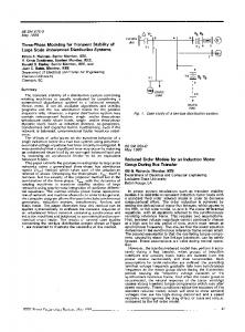
Fig. 2. (a) Architecture of the NAND-SPIN. (b)-(d) Structures and operation of the NAND-SPIN string or substring. (e) Schematic layout of an 8-bit NAND-SPIN string, where the interconnection between MTJs and access transistors is omitted for clarity. PS transistor is not shown since it can be shared by multiple strings.
Fig. 3. Timing diagram of write/read operation for the NAND-SPIN.
Fig. 4. Distribution of currents flowing through the MTJ.
(e.g. PS in Fig. 2(a)). For logic organization, the NAND-SPIN is split into multiple blocks, each of which is made up by pages. One page consists of multiple bit-cells controlled by the same word-line (WL). To access data in this NAND-SPIN, the block ID is firstly indicated, and then the column and row addresses are issued for identifying the page and bit-cells, respectively. Figure 2(e) shows the schematic layout for an 8-bit string, where the access transistors are symmetrically distributed. Figure 3 demonstrates the timing diagram for the write and read operation. The write operation is performed in two phases: first, selection transistors (PS and NS) of the addressed block are activated such that a charge current ( in Fig. 2(b)) passes the HM stripes to generate the SOT, which erases all the MTJs within the addressed block to AP states. Generally an additional magnetic field is required for the deterministic switching of perpendicular magnetization. To facilitate the device integration and avoid the additional energy consumption, the magnetic field can be replaced by the exchange bias arising from antiferromagnet/ferromagnet bilayers. Recent experiments [8]-[9] have validated this scheme by employing the antiferromagnet as an alternative to the HM (e.g. 10~20 mT exchange bias was obtained in PtMn/[Co/Ni] [8]). Second, for those bit-cells to be switched to P states, their access transistors and PS transistors are activated, whereas the NS transistors are deactivated. The bit-lines (BLs) are grounded such that a current ( in Fig. 2(b)-(d)) flows from the free layer to
TABLE I SIMULATION PARAMETERS Parameters Default values MTJ free layer thickness 1 nm Heavy metal thickness 4 nm Damping constant 0.02 ⁄ Uniaxial anisotropy constant Resistance-area product 5 Saturation magnetization 1150 ⁄ Spin Hall angle 0.3 Tunneling spin polarization 0.62 Heavy metal resistivity 200 Ratio of damping-like SOT to 0.4 field-like SOT Exchange bias 15 mT
pinned layer, which induces the STT to switch those MTJs to P states. Therefore, the NAND-SPIN is more suitable for fast sequential write operation. To perform the read operation, the access transistors and NS transistors are activated whereas the PS transistors are deactivated. Then BLs are connected to the sensing amplifier in order that the data represented by the MTJ resistance is read. Figure 2(b)-(d) show the possible structures of the string. In Fig. 2(c) the STT program current can be enhanced due to the parallel-connected HM stripes. However, the program current passing the HM may generate the SOT which disturbs the other unaddressed bit-cells. Considering that the critical current density for STT switching is much smaller than that for SOT switching, this disturbance can be minimized by adjusting the HM dimension to enlarge the margin between and . In Fig. 2(b) and (d), the disturbance can be completely avoided as long as the bit-cells are programmed in the descending order of WL number. But the STT program current becomes smaller compared with the case of Fig. 2(c). The NAND-SPIN offers the following advantages. First, the source degeneration problem is eliminated since both the erase and program currents are unidirectional. Second, the required STT current is smaller than that of the conventional STT-MRAM, as it is only responsible for high-efficiency AP-to-P switching. In particular, larger margin between the STT current and breakdown current can be obtained to optimize the trade-off between the low write error rate and high barrier reliability (see Fig. 4). Third, the integration density is higher
0741-3106 (c) 2017 IEEE. Translations and content mining are permitted for academic research only. Personal use is also permitted, but republication/redistribution requires IEEE permission. See http://www.ieee.org/publications_standards/publications/rights/index.html for more information.
This article has been accepted for publication in a future issue of this journal, but has not been fully edited. Content may change prior to final publication. Citation information: DOI 10.1109/LED.2018.2795039, IEEE Electron Device Letters
TABLE II COMPARISON OF VARIOUS MEMORIES Transistor size Write energy Maximum write per bit per bit voltage across (Feature size) (fJ) the MTJ (mV) MTJ dimension: 40 nm 40 nm NAND-SPINa STT-MRAM (SC)c STT-MRAM (RC)c
2.29 (NS)b 5.66 (Tx)b 40.33 36.66
SOT-MRAM
9 2
NAND-SPINa
1.04 (NS)b 1.33 (Tx)b
30.91 (Erase) 369.7 (Program) 627.4 (P AP) 1387 (AP P) 1183 (P AP) 419.5 (AP P) 178.6 (P AP) 127.2 (AP P)
MTJ dimension: 20 nm
STT-MRAM (SC)c STT-MRAM (RC)c SOT-MRAM
8.66 8.33 4.33 2
470 410 (P AP) 920 (AP P) 910 (P AP) 430 (AP P) N/A 20 nm
17.14 (Erase) 81.7 (Program) 145.1 (P AP) 339 (AP P) 287.7 (P AP) 98.7 (AP P) 69.76 (AP P) 83.56 (P AP)
430 380 (P AP) 900 (AP P) 900 (P AP) 410 (AP P) N/A
a
The NAND-SPIN string accommodating 32 bit-cells is organized as Fig. 2(c) (i.e. 4 bit-cells per substring multiplied by 8 substrings). The switching delay is composed of 1 ns erase operation followed by 4 ns program operation. The switching is achieved when the z-component of the magnetization crosses 0. The ratio of channel width between PS and NS transistors is set to 2.5:1. Both the HM width and the space between adjacent MTJs are equal to the MTJ size. b For the NAND-SPIN, the integration density is mainly determined by the sizes of NS transistors and access transistors (Tx), as PS transistors are shared by multiple strings. Here the NS transistor size per bit is calculated by dividing the size of a NS transistor by the amount of the bit-cells within the same string. c The intrinsic critical STT current densities for AP-to-P and P-to-AP ⁄ ⁄ switching are and , respectively[12].
compared with the standard SOT-MRAM, as each MTJ is associated with only one access transistor while the selection transistors are shared by numerous bit-cells. Finally, the read disturb promises to be significantly mitigated. As shown in Fig. 4, the read disturb margin is associated with the read current ( ) and P-to-AP STT switching current ( ). As the AP state is written by the SOT instead of the STT, the increase of is allowed to enlarge the read disturb margin. III. RESULTS AND DISCUSSIONS The simulation is performed using a CMOS FDSOI 28 nm design kit [10] and a compact model of the MTJ [11]. The resistance of the HM stripe is accounted for as well. The exchange bias is used to avoid the energy dissipation of current-induced magnetic field. Table I lists the simulation parameters which represent the state-of-the-art technologies. Table II shows the comparison of the key metrics under the same switching speed. All these memories are simulated with the same magnetic parameters. Two groups of MTJ dimensions are used to show the scalability of the NAND-SPIN. The existence of the exchange bias causes a slight tilt of the perpendicular magnetization and assists the STT switching during the programing operation of the NAND-SPIN. But the influence is negligible due to such a small magnitude (15 mT in
our simulation). For the STT-MRAM, besides the standard-connection (SC) cell shown in Fig. 1(a), we also show the results of reverse-connection (RC) cell, which has been proposed to improve the switching margin [2]. It is seen that the performances of both the STT-MRAM and SOT-MRAM are degraded by the above-mentioned drawbacks. Overall, the SOT-MRAM shows 2~4X larger bit-cell area than NAND-SPIN due to more access transistors. The STT-MRAM consumes excessive energy (3~5X compared to NAND-SPIN) and induces an overlarge write voltage (up to ~900 mV) to stress the tunnel barrier, owing to the asymmetric write operation. For instance, simulation demonstrates that ~8.66 feature-size access transistor is required by 20 nm MTJ for generating ~30 current and achieving 5 ns P-to-AP switching. However, such a large access transistor leads to an overlarge current up to ~60 for AP-to-P switching. By contrast, the NAND-SPIN avoids the above disadvantages by employing the unidirectional SOT and STT switching currents. In addition, for the structure of Fig. 2(c), we analyze the disturbance of the write current on the unaddressed bit-cells during the program operation. Based on the fitting model of [13] and our simulation results, it is estimated that the maximum switching probability induced by the write disturbance is , corresponding to ~14 current passing the HM at 20 nm dimension. This result meets the requirement of the storage application, but still needs to be improved for the application of working memory (typically ). It is important to mention that the HM stripe strongly affect the performance of the NAND-SPIN. Table II demonstrates that NS transistor size is reduced with the scaling of the MTJ, which is indeed attributed to the decrease of both the HM dimension and SOT erase current. Note that the HM thickness cannot be scaled in order to maintain the sufficiently large spin Hall angle (0.3 for W). Recently larger spin Hall angle (e.g. 0.5) has been demonstrated by optimizing the fabrication process [14]. Thereby the spin current conversion can continue to be enhanced and subsequently the performance of the NAND-SPIN promises to be further improved. On the other hand, the sensing margin (SM) of the NAND-SPIN is smaller than the STT-MRAM (23% versus 34% at 20 nm dimension) due to the additional HM resistance. Here the SM is defined as ( )⁄( ) where is the sensed voltage at AP or P state and the read current is one tenth of the critical STT switching current. The SM degradation can be compensated by the enhanced TMR effect [15]-[16] or high-reliability sensing amplifiers [17]-[18]. IV. CONCLUSION We propose a NAND-SPIN memory with flash-like write operation for high-density non-volatile memory applications. The NAND-SPIN overcomes major drawbacks of the conventional STT-MRAM and SOT-MRAM, including the source degeneration of the access transistor, the asymmetric switching of STT mechanism, and the bit-cell area overhead of SOT-MRAM. The NAND-SPIN achieves 3~5X less write energy than the STT-MRAM and 2~4X reduction in the bit-cell area compared to the SOT-MRAM at 28 nm node. The maximum write voltage across the MTJ is reduced as well.
0741-3106 (c) 2017 IEEE. Translations and content mining are permitted for academic research only. Personal use is also permitted, but republication/redistribution requires IEEE permission. See http://www.ieee.org/publications_standards/publications/rights/index.html for more information.
This article has been accepted for publication in a future issue of this journal, but has not been fully edited. Content may change prior to final publication. Citation information: DOI 10.1109/LED.2018.2795039, IEEE Electron Device Letters
REFERENCES [1] X. Fong, Y. Kim, R. Venkatesan, S. H. Choday, A. Raghunathan, and K. Roy, “Spin-Transfer Torque Memories: Devices, Circuits, and Systems,” Proc. IEEE, vol. 104, no. 7, pp. 1449–1488, Jul. 2016. DOI: 10.1109/JPROC.2016.2521712 [2] C. J. Lin, S. H. Kang, Y. J. Wang, K. Lee, X. Zhu, W. C. Chen, X. Li, W. N. Hsu, Y. C. Kao, M. T. Liu, Y. Ling, M. Nowak, N. Yu, and L. Tran. “45nm low power CMOS logic compatible embedded STT MRAM utilizing a reverse-connection 1T/1MTJ cell,” in Proc. IEEE Int. Electron Dev. Meeting, pp. 11.6.1–11.6.4, Dec. 2009. DOI: 10.1109/IEDM.2009.5424368 [3] L. Liu, C.-F. Pai, Y. Li, H. W. Tseng, D. C. Ralph, and R. A. Buhrman, “Spin-Torque Switching with the Giant Spin Hall Effect of Tantalum,” Science, vol. 336, no. 6081, pp. 555–558, May 2012. DOI: 10.1126/science.1218197 [4] I. M. Miron, K. Garello, G. Gaudin, P.-J. Zermatten, M. V. Costache, S. Auffret, S. Bandiera, B. Rodmacq, A. Schuhl, and P. Gambardella, “Perpendicular switching of a single ferromagnetic layer induced by in-plane current injection,” Nature, vol. 476, no. 7359, pp. 189–193, Aug. 2011. DOI: 10.1038/nature10309 [5] M. Cubukcu, O. Boulle, M. Drouard, K. Garello, C. O. Avci, I. M. Miron, J. Langer, B. Ocker, P. Gambardella, and G. Gaudin. “Spin-orbit torque magnetization switching of a three-terminal perpendicular magnetic tunnel junction,” Appl. Phys. Lett., vol. 104, no. 4, pp. 042406, Jan. 2014. DOI: 10.1063/1.4863407 [6] Y. Seo, K.-W. Kwon, and K. Roy, “Area-Efficient SOT-MRAM with a Schottky Diode,” IEEE Electron Dev. Lett. vol. 37, no. 8, pp. 982–985, Aug. 2016. DOI: 10.1109/LED.2016.2578959 [7] R. Micheloni, A. Marelli, and S. Commodaro, “NAND overview: from memory to systems,” in Inside NAND flash memories, Springer, 2010, pp. 19–53. [8] S. Fukami, C. Zhang, S. DuttaGupta, A. Kurenkov, and H. Ohno, “Magnetization switching by spin–orbit torque in an antiferromagnet– ferromagnet bilayer system,” Nature Mater., vol. 15, pp. 535–541, 2016. DOI: 10.1038/nmat4566 [9] Y. W. Oh, S. C. Baek, Y. M. Kim, H. Y. Lee, K.-D. Lee, C.-G. Yang, E.-S. Park, K.-S. Lee, K.-W. Kim, G. Go, J.-R. Jeong, B.-C. Min, H.-W. Lee, K.-J. Lee, and B.-G. Park, “Field-free switching of perpendicular magnetization through spin–orbit torque in antiferromagnet/ferromagnet/oxide structures,” Nature Nanotechnol.,vol. 11, pp. 878–884, 2016. DOI: 10.1038/NNANO.2016.109 [10] STMicroelectronics CMOS028 Design Rule Manual, 2013. [11] Z. Wang, W. Zhao, E. Deng, J. O. Klein, and C. Chappert, “Perpendicular-anisotropy magnetic tunnel junction switched by spin-Hall-assisted spin-transfer torque,” J. Phys. D: Appl. Phys., vol. 48, no. 6, pp. 065001–65007, 2015. DOI: 10.1088/0022-3727/48/6/065001 [12] S. -W. Chung, T. Kishi, J. W. Park, M. Yoshikawa, K. S. Park, T. Nagase, K. Sunouchi, H. Kanaya, G. C. Kim, K. Noma, M. S. Lee, A. Yamamoto, K. M. Rho, K. Tsuchida, S. J. Chung, J. Y. Yi, H. S. Kim, Y. S. Chun, H. Oyamatsu, and S. J. Hong, “4Gbit density STT-MRAM using perpendicular MTJ realized with compact cell structure,” in Proc. IEEE Int. Electron Dev. Meeting, pp. 27.1.1–27.1.4, Dec. 2016. DOI : 10.1109/IEDM.2016.7838490 [13] C. Zhang, S. Fukami, H. Sato, F. Matsukura, and H. Ohno, “Spin-orbit torque induced magnetization switching in nano-scale Ta/CoFeB/MgO,” Appl. Phys. Lett., vol. 107, no. 1, pp. 012401, 2015. DOI: 10.1063/1.4926371 [14] K.-U. Demasius, T. Phung, W. Zhang, B. P. Hughes, S.-H. Yang, A. Kellock,W. Han, A. Pushp, and S. S. P. Parkin, “Enhanced spin–orbit torques by oxygen incorporation in tungsten films,” Nature Comm., vol. 7, no. 10644, 2016. DOI: 10.1038/ncomms10644 [15] N. Tezuka, S. Oikawa, I. Abe, M. Matsuura, S. Sugimoto, K. Nishimura, and T. Seino, “Perpendicular Magnetic Tunnel Junctions With Low Resistance-Area Product: High Output Voltage and Bias Dependence of Magnetoresistance,” IEEE Magn. Lett., vol. 7, no. 3104204, 2016. DOI: 10.1109/LMAG.2016.2584582 [16] Y. J. Song, J. H. Lee, H. C. Shin, K. H. Lee, K. Suh, J. R. Kang, S. S. Pyo, H. T. Jung, S. H. Hwang, G. H. Koh, S. C. Oh, S. O. Park, J. K. Kim, J. C. Park, J. Kim, K. H. Hwang, G. T. Jeong, K. P. Lee, and E. S. Jung, “Highly functional and reliable 8Mb STT-MRAM embedded in 28nm logic,” in Proc. IEEE Int. Electron Dev. Meeting, pp. 27.2.1–27.2.4, Dec. 2016. DOI: 10.1109/IEDM.2016.7838491 [17] Y. Chen, H. Li, X. Wang, W. Zhu, W. Xu, and T. Zhang, “A 130 nm 1.2 V/3.3 V 16 Kb spin-transfer torque random access memory with
nondestructive self-reference sensing scheme,” IEEE J. Solid-State Circuits, vol. 47, no. 2, pp. 560–573, Feb. 2012. DOI: 10.1109/JSSC.2011.2170778 [18] W. Kang, T. Pang, W. Lv, and W. Zhao, “Dynamic dual-reference sensing scheme for deep submicrometer STT-MRAM,” IEEE Trans. Circuits Syst. I, Reg. Papers, vol. 64, no. 1, pp. 122–132, Jan. 2017. DOI: 10.1109/TCSI.2016.2606438
0741-3106 (c) 2017 IEEE. Translations and content mining are permitted for academic research only. Personal use is also permitted, but republication/redistribution requires IEEE permission. See http://www.ieee.org/publications_standards/publications/rights/index.html for more information.