IEEE TRANSACTIONS ON APPLIED SUPERCONDUCTIVITY, VOL. 19, NO. 3, JUNE 2009
741
High Linearity SQIF-Like Josephson-Junction Structures Victor K. Kornev, Igor I. Soloviev, Nikolai V. Klenov, and Oleg A. Mukhanov, Senior Member, IEEE
Abstract—Recently we reported design approaches for the synthesis of multi-SQUID structures capable of providing high linearity voltage response. These structures were developed to form periodic voltage responses. This paper presents possible design solutions for multi-element structures providing SQIF-like high linearity voltage response. The approach is based on the use of a differential scheme of two parallel SQIFs with arrays oppositely frus. The differential scheme entrated by applied magnetic field ables a high efficiency synthesis of highly linear SQIF response by subtraction of deviations from linear law. Index Terms—Amplifiers, differential scheme, dynamic range, high linearity, parallel SQIF, SQUID arrays.
I. INTRODUCTION
R
ECENTLY we have reported an approach to the synthesis of multi-SQUID structures capable of providing high linearity voltage response [1], [2]. The approach is based on the formation of serial structures capable of providing periodic triangular voltage response to a homogeneous magnetic field with “frequency” spectrum as follows:
(1) is width of the triangular pulse with repetition cycle . Two ways were suggested for the structure formation. The first one is to use interferometer cells (dc SQUIDs) providing harmonic voltage response with “frequency” , where is effective area of the interferometer cell which belongs to the -th group. In case when input signal is a control line current (instead of ), the effective area should be replaced by mutual inductance , i.e. . It is significant that spectrum of the voltage response with contains only odd harmonics with minimum period amplitudes decreasing monotonically as the squared harmonic number:
Fig. 1. Differential array structure consisting of two series arrays of dc interferometers with biasing I = I , where I —critical current of the interferometers. In one array, each cell is biased by magnetic flux 8 =2. Additional flux 8 =4 is applied to all cells to set the operating point.
The second way is to form a differential scheme using se, rial arrays of interferometer cells biased by current where is the interferometer critical current. Voltage response of such an array is characterized by numerous harmonics with monotonically decreasing amplitudes:
where
(2) Manuscript received August 25, 2008. First published June 30, 2009; current version published July 10, 2009. This work was supported by ONR under Grant RUP1-1493-05-MO via CRDF GAP and in part by ISTC Grant 3743 and Russian grants on scientific schools PGSS 5408.2008.2 and PGSS 133.2008.2. V. K. Kornev, I. I. Soloviev and N. V. Klenov are with Moscow State University, Moscow 119991, Russia (e-mail:
[email protected]). O. A. Mukhanov is with HYPRES, Elmsford, NY 10523, USA (e-mail:
[email protected]). Color versions of one or more of the figures in this paper are available online at http://ieeexplore.ieee.org. Digital Object Identifier 10.1109/TASC.2009.2019543
(3) Apart from a few first harmonics, the amplitude decrease law is . Differential scheme of two serial arrays with quite close to -frustration provides subtraction of all even harmonics, and therefore the resulting response becomes close enough to . Fig. 1 shows schematithe triangular one with cally the differential array structure and magnetic biasing of the arrays. One can increase the linearity of the differential array voltage response. For this purpose, we should add to the array structure a few cells with sinusoidal responses generating necessary spectrum tones. These cells are dc interferometer biased in order to generate as well above critical current close to a sinewave as possible. These additional cells are to correct the initial spectral components in (3) in order to approach the desired spectrum (2). Now, we replace the individual interferometer cells in both serial arrays by parallel arrays and arrive to a parallel-series differential structure. In this paper we present further development of such a differential structure. Considerable increase in the voltage response linearity results from the use of parallel SQIFs [3] with synthesized array structure instead of ordinary parallel arrays with randomly chosen parameters.
1051-8223/$25.00 © 2009 IEEE Authorized licensed use limited to: Princeton University. Downloaded on July 25, 2009 at 16:47 from IEEE Xplore. Restrictions apply.
742
IEEE TRANSACTIONS ON APPLIED SUPERCONDUCTIVITY, VOL. 19, NO. 3, JUNE 2009
Fig. 2. Iterative algorithm for finding an optimal SQIF area distribution a(x).
Fig. 3. Differential scheme of two parallel SQIFs frustrated by 8 =2.
II. SQIF-BASED DIFFERENTIAL STRUCTURES A. Optimal Cell Area Distribution Differential scheme of two parallel SQIFs oppositely frus(see Fig. 3) is able to trated by an applied magnetic field provide extremely linear voltage response in case of properly synthesized SQIF structure. At vanishing inductances of the interferometer cells one can use analytical relation for the parallel SQIF response [3]–[5]: (4) where
is structural factor: (5)
—bias current, —total critical current, —number of —area of the -th interferometer cell. Josephson junctions, At sufficiently high number one can use integration instead of summation, and relation (5) can be transformed as follows: (6) We need to find the specific distribution of the interferometer along SQIF-structure to make the cell areas differential circuit voltage response (7)
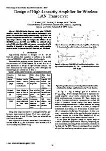
Fig. 4. (a) The derived optimal distribution (9) of the cell areas along SQIF structure. (b) Voltage response (solid line) of the differential circuit of two parallel SQIFs with the derived cell area distribution at optimal magnetic frustration. The response linearity within the shaded central area reaches 101 dB. The frustrated SQIF responses are shown by dashed lines.
by means of numerical simulation, using, e.g. PSCAN simulation package [6]. The problem can have more than one solution. We have found ; the best some analytical approximations for solutions at one is shown below:
close to a linear law (9) (8) where , where . in a signal region Relations (2)–(6) allow deriving master equations and stating minimization problem for the obtained functional in order to . One can use an iterative alfind an optimal distribution gorithm to find the problem solution, starting from some initial approximation (Fig. 2). In case of finite inductances of the inhas to be calculated terferometer cells, the SQIF response
—total area of SQIF.
B. Response Linearity Fig. 4 shows both the cell area distribution (9) and the differential circuit voltage response. The linearity of the voltage response within the shaded central area reaches 101 dB. To es-like input signal and then timate the linearity, we applied
Authorized licensed use limited to: Princeton University. Downloaded on July 25, 2009 at 16:47 from IEEE Xplore. Restrictions apply.
KORNEV et al.: HIGH LINEARITY SQIF-LIKE JOSEPHSON-JUNCTION STRUCTURES
743
of the elements connected in series is responsible for the output signal amplitude, while tonal number of Josephson junctions is responsible for dynamic range of the structure. Varying the number of elements connected in parallel and in series , one can change impedance of the structure in wide range. III. INDUCTANCE INFLUENCE A. From Model to Real Structure
Fig. 5. Linearity of the differential voltage response versus both the number N of SQIF cells (a) and the spread in the cell areas at N = 36 (b).
There are several problems which should be solved in order to realize the potentially high performance of two-dimensional SQIF structures. One should note that the optimally synthesized structure of parallel SQIF was derived using the RSJ model of Josephson junctions and also assuming vanishing coupling in. This means that the performance of real ductances SQIF structures will likely to be lower. One can suggest three approaches of preserving the expected high performance: (i) to provide the closest approach of the experimental Josephson junction characteristics to the ones given by RSJ model, (ii) to synthesize an optimal SQIF structure based on experimental Josephson junction characteristics and unavoidable circuit parasitics using numerical simulation technique and iterative algorithm (Fig. 2), and (iii) to utilize circuit techniques to minimize impact of parasitic parameters to the overall circuit performance. In all probability, an optimal strategy should be based on combination of all these approaches. B. Shunting of Coupling Inductances
Fig. 6. Two-dimensional differential serial-parallel SQIF structure.
studied spectrum of output signal. The ratio of the fundamental to the highest spur was used to characterize the response linearity. It was found that the high linearity can be obtained using relatively small number of SQIF cells with the cell areas fitted to (9). Fig. 5(a) shows that the linearity increases rapidly with reaches a plateau where the linearity number and at is about 101 dB. As for the impact of fabrication spread in the cell areas, Fig. 5(b) shows that the tolerable spread is about 4% ; and then the linearity decreases with the spread at value. Approximately the same result was obtained for spread in critical currents of Josephson junctions. Larger number of N can be used in order to decrease impact of the fabrication spread in the SQIF circuit parameters as well as to increase dynamic up to the linearity level obtained. range proportional to C. Two-Dimensional Structure Both the dynamic range and the output signal amplitude can be additionally increased by connection of the differential SQIF structures in series, i. e. by integrating a two-dimensional differential serial-parallel SQIF structure (see Fig. 6). The number
In particular, in order to minimize the negative influence of the finite value of coupling inductance to the voltage response connected in parlinearity, one can use shunting resistors allel to these inductances. Due to the fact that impedance of the circuit becomes low enough at Josephson oscillation frequency, the parallel array voltage response approaches the one down for smaller and smaller inductance with decreasing to some optimal resistance value depending on the normalized inductance . The further increase in leads to some other linearity distortions. Therefore the most efficient way is the synthesis of an optimal SQIF structure with the cell area distributaking into account realistic finite values of found tion from the circuit layout. In this case, one should use a high performance numerical simulation technique (e.g., PSCAN [6]) for calculation of the SQIF voltage response in every cycle of the iterative algorithm (Fig. 2) which is to be used to solve master equation. The shunting technique utility is confirmed by the results of numerical simulations presented in Fig. 7. One can see that at (where is Josephson junction normal resistance) voltage response of the parallel array of 6 junctions with nears to the one at vanishing coupling inductances. As a consequence, we observe the required linear voltage response of the differential scheme of two parand coupling inductances each allel SQIFs with shunted by resistor .
Authorized licensed use limited to: Princeton University. Downloaded on July 25, 2009 at 16:47 from IEEE Xplore. Restrictions apply.
744
IEEE TRANSACTIONS ON APPLIED SUPERCONDUCTIVITY, VOL. 19, NO. 3, JUNE 2009
Fig. 7. (a) Voltage response of a parallel array of N = 6 junctions coupled by inductances with normalized value l = 1 at different shunting resistors R connected in parallel to the coupling inductances. Dash line shows voltage response of the array at the vanishing coupling inductance. (b) Voltage response of the differential circuit of two frustrated parallel arrays of N = 6 Josephson junctions at l = 1 and R = R , where R —Josephson junction normal resistance.
IV. CONCLUSIONS The differential scheme of two magnetically frustrated parallel SQIFs is developed to obtain highly linear single-peak voltage response. The response linearity can be increased up to 120 dB by finding the optimal SQIF cell area distribution using numerical simulations with realistic circuit parameters. High linearity can be attainable for relatively small number of junctions. Such a circuit allows us to achieve high-performance in a two-dimensional serial-parallel SQIF-like array. Varying the number of elements connected in parallel and in series, one can set the impedance value needed to minimize the negative impact of the load. The synthesized structures can be used to design high-performance amplifiers and electrically small active antennas for megahertz and gigahertz frequency ranges. ACKNOWLEDGMENT The authors thank Alex Kirichenko and Henrik Engseth for valuable help and discussion.
REFERENCES [1] V. K. Kornev, I. I. Soloviev, N. V. Klenov, and O. A. Mukhanov, “Synthesis of high linearity array structures,” Superconducting Science and Technology, vol. 20, pp. S362–S366, 2007. [2] V. K. Kornev, I. I. Soloviev, N. V. Klenov, and O. A. Mukhanov, “High linearity Josephson-junction array structures,” Physica C, vol. 468, pp. 813–816, 2008. [3] J. Oppenlaender, C. Haeussler, and N. Schopohl, “Non- 8 -periodic macroscopic quantum interference in one-dimensional parallel Josephson junction arrays with unconventional grating structure,” Phys. Rev. B, vol. 63, pp. 024511-1–024511-9, 2001. [4] V. Schultze, R. I. Jsselsteijn, H.-G. Meyer, J. Oppenländer, C. Häussler, and N. Schopohl, “High- T superconducting quantum interference filters for sensitive magnetometers,” IEEE Trans. Appl. Supercond., vol. 13, no. 2, pp. 775–778, 2003. [5] V. K. Kornev, I. I. Soloviev, J. Oppenlaender, C. Haeussler, and N. Schopohl, “Oscillation linewidth and noise characteristics of parallel SQIF,” Superconductor Science and Technology, vol. 17, no. 5, pp. S406–S409, 2004. [6] V. K. Kornev and A. V. Arzumanov, “Numerical simulation of Josephson-junction system dynamics in the presence of thermal noise,” in Inst. Physics Conf. Ser., 1997, no. 158, pp. 627–630, IOP Publishing Ltd.
Authorized licensed use limited to: Princeton University. Downloaded on July 25, 2009 at 16:47 from IEEE Xplore. Restrictions apply.