Abstract. We continue the development of high-order accurate thin layer approxima- tions for time-domain electromagnetics and focus in this paper on thin trans-.
High-order accurate thin layer approximations for time-domain electromagnetics. Part II: Transmission layers S. Chuna , H. Haddarb , and J.S. Hesthavenc a
The Institute for Mathematical Sciences, 53 Prince’s Gate, South Kensington, London, SW7 2PG, United Kingdom b Ecole Polytechnique, Route de Saclay, 91128 Palaiseau Cedex, France c Division of Applied Mathematics, Brown University, Providence, RI 02912, USA
Abstract We continue the development of high-order accurate thin layer approximations for time-domain electromagnetics and focus in this paper on thin transmission layers. The thin transmission layer approximations are valid for general isotropic materials and certain classes of anisotropic materials. The models also allow the inclusion of smoothly curved layers. Both dielectric and magnetic materials can be considered. These models are non-trivial and we discuss their formulation, properties, and implementation in the context of discontinuous Galerkin methods which emerge as being particularly well suited for this family o f models. The range of validity, accuracy, and stability of the resulting schemes is demonstrated through one- and two-dimensional examples. Key words: Thin layer approximations, Transmission, Maxwell’s equations, discontinuous Galerkin methods. 1. Introduction In this work we continue the development of high-order order accurate thin layer models for time-domain electromagnetics and extend it to the important case of transmission layers. The approach taken is based on asymptotic expansion approach developed in in [7] for isotropic materials and coatings of metallic objects which we extended in [5] to more general coatings Preprint submitted to Journal of Computational and Applied MathematicsMarch 12, 2009
and demonstrated their efficient and accurate implementation in high-order accurate discontinuous Galerkin methods. Whereas there is a rich literature on approximate boundary conditions for thin coatings (see e.g. [9]), past work on accurate models for transmission layers is very sparse. This is particularly true when one considers models that accurately and efficiently account for curvilinear behavior of the transmission layer. However, the applications for such models are many, including photonic crytals, thin biological shells in medical imaging and general thin shells in imaging and inverse imaging. To appreciate the objective of thin layer approximations, recall that we can recover the exterior field of an object knowing only the field along a closed contour or on the surface of the object. Hence, we can seek to compute the exterior field using a thin layer approximation at the boundary values of exterior field only. The problem with a thin dielectric or magnetic layer can therefore be converted into a problem with a two separated media and a complex boundary condition that connects the two to accurately model the exchange of electromagnetic energy between the two media. The importance of this arises from the efforts of reducing the computational constraints due to the thin layer. Computing without the need to directly resolve the thin layer significantly reduces the size of the discrete model and consequently reduces the computation expense, especially when the layer is thin compared to the wavelength of the incident wave. In this paper, high-order thin layer approximations for very general transmission layers are derived and their implementation and performance studied in the context of discontinuous Galerkin method. What remains is organized as follows. In Sec. 2 we set the stage for the development of the thin layer models and outline the central ideas of effective interface conditions (EIC) for time-domain electromagnetics. This lays the foundation for the detailed development of a hierarchy of high-order EIC models in Sec. 3 and the detailed formulation of models of increasing order of accuracy. We shall discuss stability of these models and establish energy stability for the high-order accurate models. In Sec. 4 we discuss in detail the implementation of the EIC models in the framework of discontinuous Galerkin methods which emerge as being particularly well suited for the EIC for time-domain electromagnetics developed in this work. Section 5 is devoted to an in depth discussion of the implementation and testing of EIC in one-dimensional problems, including extensions to multiple interfaces and periodic crystals. Both stability and accuracy of the EIC models are 2
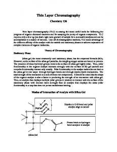
confirmed. The benchmarking continues in Sec. 6 where we focus on twodimensional transmission layers, discuss their implementation, and highlight the benefit of being able to accurately account for the curvilinear nature of the layer. This is sought to be extended to non-smooth layers by considering local regularization and the results illustrate the perspectives in this. The results also show the ability of the EIC models to accurately model layers as thick as a wavelength at which point the use of EIC becomes less important. Section 7 contains a few concluding remarks and some suggestions for future work. 2. Problem setting Let us consider a thin layer (Ωη ) of thickness η that encloses a connected domain of R3 . Let ∂Ω+ , and ∂Ω− be the outer and inner boundary of the thin layer, respectively and let Γ be defined as Γ = 21 (∂Ω+ + ∂Ω− ), i.e., the parallel interface located half way between the two boundaries (see Fig. 1). We assume that Γ is a C ∞ surface and that the outer and inner boundaries ˆ where we denote by n ˆ the normal of Ωη can be expressed as Γ ± (η/2)n, vector on Γ. Ω−
η
Ωη Γ
Ω+ ˆ n
Figure 1: Notation for domains and boundaries
Let εˆ, µ ˆ be the permittivity and permeability tensors, respectively, in the thin layer Ωη . We assume that these tensors are independent of η and of the normal coordinate and that they can be decomposed as ˆ ⊗ n) ˆ εˆ = εˆT + εn (n ˆ ⊗ n) ˆ µ ˆ=µ ˆT + µn (n
(1)
where εn and µn are positive scalar functions and εˆT and µ ˆT are positive ˆ =µ ˆ = 0). We also denote by εˆ± , µ tangential tensors (satisfying εˆT · n ˆT · n ˆ± ± the permittivity and permeability tensors, respectively, in Ω . 3
Let E η , H η be the electric and magnetic vector fields, respectively, in Ω , and let E ± , H ± be the electric and magnetic fields, respectively, in Ω± . Each of these vector fields must satisfy Maxwell’s equations, η
εˆ± ∂t E ± − ∇ × H ± = 0, µ ˆ± ∂t H ± + ∇ × E ± = 0 εˆ∂t E η − ∇ × H η = 0, µ ˆ∂t H η + ∇ × E η = 0
on Ω± on Ωη
(2) (3)
subject to tangential continuity ˆ = E η × n, ˆ E± × n
ˆ = H η × n, ˆ H± × n
on ∂Ωη = ∂Ω± ,
(4)
and with initial data which we assume to be compactly supported in Ω+ ∪Ω− . Remark 1. We assumed for the shake of simplicity that the medium and the thin layer are non conductive. However, the following generalizes to the case with conductivity by replacing εˆ∂t with εˆ∂t + σ ˆ and by assuming that σ ˆ has a similar decomposition into normal and tangential parts, cf. Eq.(1), inside the thin layer. We seek to construct interface conditions that connect the tangential components of (E + , H + ) on ∂Ω+ with the tangential components of (E − , H − ) on ∂Ω− without requiring the computation of the exact solution to (3), but rather in such a way that we approach the exact conditions as η → 0. More precisely we aim to derive local boundary operators Bη,± on Γ such that, at k least formally, + − ˆ ∂Ω+ , H + × n| ˆ ∂Ω+ ) = Bη,− ˆ ∂Ω− , H − × n| ˆ ∂Ω+ ) + O(η k+1 ). Bη,+ k (E × n| k (E × n| (5) k+1 The interface conditions obtained after removing the O(η ) terms are then denoted by Effective Interface Conditions (EIC) of order k+1 (with respect to η). Our construction will be based a generalization of the scaled asymptotic expansion introduced in [7] for the thin coating case and studied in that case in detail in [5]. In the present work, we restrict ourselves in to the formal stage and concentrate on the numerical validation of the order of accuracy of the obtained interface conditions. We will also study the stability in time of the initial boundary value problems, as the second important step towards a rigorous error analysis.
4
3. Derivation and analysis of the interface conditions In the following we discuss in some detail the development of the interface conditions and the model hierarchy as well as provide some analysis to cast light on the basic properties of the conditions. 3.1. Scaled asymptotic expansion The formal derivation of the EICs is based on the ansatz �
E η (x, t) = E 0 (xΓ , ηs , t) + ηE 1 (xΓ , ηs , t) + η 2 E 2 (xΓ , ηs , t) + · · · H η (x, t) = H 0 (xΓ , ηs , t) + ηH 1 (xΓ , ηs , t) + η 2 H 2 (xΓ , ηs , t) + · · ·
(6)
for all x ∈ Ωη where ˆ x = xΓ + s n
(7)
with xΓ being �the orthogonal projection of x on Γ. The fields (E k , H k ) are � 1 1 + defined on Γ× − 2 , 2 ×R and are assumed to be bounded with respect to η. We intentionally used notation without explicit mention of the dependence with respect to η as in the formal identification we assume that these terms are independent of η. Let ∇Γ be the surface gradient operator and C be the curvature tensor ˆ Following [7], for V being a vector field defined in Ωη , we on Γ (C = ∇Γ n). ˆ have, with x = xΓ + sn, ˆ curlV = TΓs V − ∂s (V × n),
(8)
where, ˆ n ˆ + [Rs ∇Γ (V · n)] ˆ ×n ˆ − (Rs C V ) × n. ˆ TΓs V = [(Rs ∇Γ ) · (V × n)]
(9)
The operator Rs is defined on Γ by ˆ =0 Rs (Πk + s C) = Πk , Rs n with Πk being the orthogonal � � projection operator on the tangent plane to Γ. For (xΓ , ν, t) ∈ Γ × − 12 , 21 × R+ let us set �
˜ η (xΓ , ν, t) = E 0 (xΓ , ν, t) + ηE 1 (xΓ , ν, t) + η 2 E 2 (xΓ , ν, t) + · · · , E ˜ η (xΓ , ν, t) = H 0 (xΓ , ν, t) + ηH 1 (xΓ , ν, t) + η 2 H 2 (xΓ , ν, t) + · · · . H (10) 5
Using (6) and (9), Eq. (3) yields ˜ η ) = 0, ˜ η − TΓην H ˜ η − 1 ∂ν (n ˆ ×H εˆ∂t E η ˜ η + 1 ∂ν (n ˜ η ) = 0, ˆ ×E µ ˆ∂t H η + TΓην E
(11) (12)
η
� � in Γ × − 21 , 12 × R+ . Assuming the validity of the Taylor expansion Rην = Πk +
∞ X
(−ην C)i ,
i=1
one recovers an expansion of the operator TΓην on the form TΓ = ην
∞ X
(i)
(−ην)i TΓ ,
(13)
i=0 (i)
where the operators TΓ are defined by (i) ~ (i) × (V · n) ˆ +∇ ˆ − (Ci+1 V ) × n ˆ TΓ V = (∇Γ(i) × V ) n Γ (i) ~ (i) for the vector-field, V . The surface operators ∇ Γ × and ∇Γ × are defined on Γ by
~ (i) × v = (Ci ∇Γ v) × n, ˆ ∇ Γ
i ˆ ∇(i) Γ × V = (C ∇Γ ) · (V × n).
for the general scalar field v. Inserting (10) into (11)-(12) and using the Taylor expansion (13), yields after equating the terms of same order in η, ˆ = 0, ∂ν (E 0 × n) ˆ = 0, ∂ν (H 0 × n)
(14) (15)
and for k ≥ 0, ˆ =µ ∂ν (E k+1 × n) ˆ∂t H k +
k X
ˆ = −ˆ ∂ν (H k+1 × n) ε∂t E k +
(k−i)
(−ν)k−i TΓ
i=0 k X
E i,
(k−i)
(−ν)k−i TΓ
H i.
(16)
(17)
i=0
The derivation of the interface conditions follows from the assumption that the boundary values ˆ H k (xΓ , 12 , t)×n ˆ or (E k (xΓ , − 21 , t)×n, ˆ H k (xΓ , − 21 , t)×n) ˆ (E k (xΓ , 12 , t)×n, 6
are known, then one can inductively solve (14)-(15) and (16)-(17) with respect to ν. The interface condition is recovered by expressing the other boundary values from these expressions. We shall explain in the sequel how to perform this technical step (with minimal efforts) so that symmetric expressions (of interface conditions) are directly obtained. As a first step we separate Eqs. (16)-(17) into tangential and normal parts of the equations. Using the notation ˆ × (V × n), ˆ V T := n one gets, after respectively taking the cross product and dot product of (16)ˆ (17) with respect to n, ˆ = µ ∂ν (E k+1 × n) ˆT ∂t (H k )T +
k X
~ Γ(k−i) × (E i · n) ˆ (−ν)k−i ∇
i=0
−
k X
ˆ (−ν)k−i (Ck−i (E i )T ) × n,
(18)
i=0
ˆ = −ˆ ∂ν (H k+1 × n) εT ∂t (E k )T +
k X
~ (k−i) × (H i · n) ˆ (−ν)k−i ∇ Γ
i=0
−
k X
ˆ (−ν)k−i (Ck−i (H i )T ) × n,
(19)
i=0
ˆ = εn ∂t (E k · n)
k X
ˆ =− µn ∂t (H k · n)
(−ν)k−i ∇Γ(k−i) × (H i )T
i=0 k X
(−ν)k−i ∇Γ(k−i) × (E i )T
(20)
(21)
i=0
One is able to explicitly express the boundary values on the outer boundary ˆ and H k (xΓ , 12 , t) × n ˆ in terms of the boundary values on E k (xΓ , 12 , t) × n 1 ˆ and H k (xΓ , − 12 , t) × n ˆ by inductively the inner boundary E k (xΓ , − 2 , t) × n solving (14)-(15) and (18)-(21). Let V k represent E k or H k , and use the notation 1 V± k (xΓ , t) := V k (xΓ , ± 2 , t)
7
[V k ] := V
+ k
−V
− k,
1 +V− hV k i := (V + k ) and V k := 2 k
Z
1 2
V k (·, ν, ·)dν,
− 12
for the jump, the mean, and the layer average, respectively. To derive symmetric expressions for interface conditions we express V k × ˆ in terms of hV i × ni ˆ for i ≤ k by using the formula n ! Z ν Z 1 2 1 ∂ν V k (xΓ , ξ, t)dξ . V k (xΓ , ν, t) = hV k i(xΓ , t)+ ∂ν V k (xΓ , ξ, t)dξ − 2 − 12 ν (22) 3.2. Terms of order 0 Integrating (14) and (15) across the layer yields ˆ = 0 and [E 0 × n]
ˆ = 0. [H 0 × n]
(23)
We recognize this as being the simplest case when one ignores the presence of the layer all together. 3.3. Terms of order 1 Equations (18)-(19) yields for k = 0, ~ Γ × (E 0 · n) ˆ = µ ˆ − (C(E 0 )T ) × n, ˆ ∂ν (E 1 × n) ˆT ∂t (H 0 )T + ∇ (24) ~ ˆ = −ˆ ˆ − (C(H 0 )T ) × n. ˆ (25) ∂ν (H 1 × n) εT ∂t (E 0 )T + ∇Γ × (H 0 · n) We observe from (14) and (15) that ˆ = hE 0 × ni ˆ and H 0 × n ˆ = hH 0 × ni. ˆ E0 × n
(26)
Equations (20)-(21) yield for k = 0, ˆ = ∇Γ × (H 0 )T εn ∂t (E 0 · n) ˆ = −∇Γ × (E 0 )T µn ∂t (H 0 · n)
(27) (28)
Integrating (24) and using (27) and (26) yields ~ Γ × E0 · n [E 1 × n] ˆ =µ ˆ − (Ch(E 0 )T i) × n ˆ ˆT ∂t h(H 0 )T i + ∇ ε ∂ E ·n n t 0 ˆ = ∇Γ × h(H 0 )T i 8
(29)
Similarly, integrating (25) across the layer yields, after using (28) and (26), the result ~ Γ × H0 · n [H 1 × n] ˆ − (Ch(H 0 )T i) × n ˆ ˆ = −ˆ εT ∂t h(E 0 )T i + ∇
(30)
µ ∂ H ·n n t 0 ˆ = −∇Γ × h(E 0 )T i 3.4. Terms of order 2 Equations (18)-(19) yields for k = 1, ~ Γ × (E 1 · n) ˆ = µ ˆ − (C(E 1 )T ) × n ˆ ∂ν (E 2 × n) ˆT ∂t (H 1 )T + ∇ (1) 2 ~ × (E 0 · n) ˆ + ν(C (E 0 )T ) × n, ˆ −ν ∇ Γ
(31)
~ Γ × (H 1 · n) ˆ = −ˆ ˆ − (C(H 1 )T ) × n ˆ ∂ν (H 2 × n) εT ∂t (E 1 )T + ∇ (1) 2 ~ × (H 0 · n) ˆ + ν(C (H 0 )T ) × n. ˆ −ν ∇ (32) Γ Applying (22) to (24)-(25) implies � �
0�
1 �
0� 0 1 ~ ˆ − (C E T ) × n ˆ , (33) ˆ = E ×n ˆ +ν µ E ×n ˆT ∂t H T + ∇Γ × E · n � �
�
�
� ~ Γ × H0 · n ˆ = H1 × n ˆ − ν εˆT ∂t E 0T − ∇ ˆ + (C H 0T ) × n ˆ . (34) H1 × n Hence, ˆ = hE 1 × ni ˆ E1 × n
and
ˆ = hH 1 × ni. ˆ H1 × n
(35)
Equations (20)-(21) likewise yield for k = 1, ˆ = ∇Γ × (H 1 )T − ν∇(1) εn ∂t (E 1 · n) Γ × (H 0 )T (1) ˆ = −∇Γ × (E 1 )T + ν∇Γ × (E 0 )T . µn ∂t (H 1 · n)
(36) (37)
Therefore, using (35), ˆ = ∇Γ × h(H 1 )T i E1 · n
and
ˆ = −∇Γ × h(E 1 )T i. H1 · n
(38)
Integrating (31) across the layer yields, upon using (38) and (35), we recover ~ Γ × E1 · n [E 2 × n] ˆ =µ ˆ − (Ch(E 1 )T i) × n ˆ ˆT ∂t h(H 1 )T i + ∇ (39) ˆ = ∇Γ × h(H 1 )T i εn ∂t E 1 · n while for (32) we obtain ~ Γ × H1 · n [H 2 × n] ˆ = −ˆ ˆ − (Ch(H 1 )T i) × n ˆ εT ∂t h(E 1 )T i + ∇ µ ∂ H ·n n t 1 ˆ = −∇Γ × h(E 1 )T i 9
(40)
3.5. Terms of order 3 for planar boundaries As is evident, the calculations become more involved as the approximation order increases. This complexity is mainly due to the presence of geometrical terms related to the curvature. Our goal here is to offer insight into what happens for higher order approximations in terms of stability in time. To maintain a reasonable technicality we restrict ourselves to the case of planar boundary, i.e., when C = 0. Let us introduce the operators ~ Γ × (εn ∂t )−1 ∇Γ ×, AH := µ ˆT ∂t + ∇ ~ Γ × (µn ∂t )−1 ∇Γ ×, AE := εˆT ∂t + ∇
(41)
where (εn ∂t )−1 (resp. (µn ∂t )−1 ) denotes the causal inverse of εn ∂t and µn ∂t . Equations (18)-(21) reduce to ˆ = AH (H k )T ∂ν (E k+1 × n)
ˆ = AE (E k )T . and ∂ν (H k+1 × n)
(42)
One easily recovers that ˆ n, ˆ ˆ 21 (ν − 12 )(ν + 21 )AH (AE h(E 0 )T i× n)× (E 2 )T = h(E 2 )T i−νAH h(H 1 )T i× n− ˆ 21 (ν− 21 )(ν+ 12 )AE (AH h(H 0 )T i×n)× ˆ n. ˆ (H 2 )T = h(H 2 )T i+νAE h(E 1 )T i×n− Consequently, by integrating (42) for k = 2 with respect to ν one obtains � 1 ˆ ×n ˆ , [(E 3 )T ] = AH h(H 2 )T i + 12 AE (AH h(H 0 )T i × n) (43) � 1 ˆ ×n ˆ . AH (AE h(E 0 )T i × n) [(H 3 )T ] = −AE h(E 2 )T i + 12 3.6. EIC of up to order 4 To obtain the interface conditions, we first observe that ˆ ∂Ω± (xΓ , t) = (E ± × n)|
Pk
ˆ + O(η k+1 ), η i E i (xΓ , ± 12 , t) × n
ˆ ∂Ω± (xΓ , t) = (H ± × n)|
Pk
ˆ + O(η k+1 ), η i H i (xΓ , ± 12 , t) × n
i=0
i=0
as a consequence of (4) and ansatz (6). Hence, if one denotes by [E η ] := E + |∂Ω+ − E − |∂Ω−
1 and hE η i := (E + |∂Ω+ + E − |∂Ω− ), 2 10
with similar notation for [H η ] and hH η i, one recovers from (23), (29), (30), (39) and (40) ˆ = ηAH h(H η )T i − η(Ch(E η )T i) × n ˆ + O(η 3 ) [E η × n] (44) ˆ = −ηAE h(E η )T i − η(Ch(H η )T i) × n ˆ + O(η 3 ) [H η × n] An expression of a third order EIC is therefore obtained by neglecting the O(η 3 ) terms. In the case of planar boundaries, combining the previous condition with (43) shows that � 1 2 ˆ ×n ˆ + O(η 4 ), ˆ = ηAH h(H η )T i + 12 η AE (AH h(H η )T i × n) [E η × n] � 1 2 ˆ ×n ˆ + O(η 4 ), ˆ = −ηAE h(E η )T i + 12 η AH (AE h(E η )T i × n) [H η × n] (45) which yields an expression for a fourth order EIC by neglecting the O(η 4 ) terms. Let us also remark that by computing the fourth order terms in the asymptotic expansion, one can prove that the O(η 4 ) is in fact O(η 5 ), reflecting that the obtained EIC is in fact of fifth order. 3.7. Stability and energy conservation These conditions will be referred as “natural EIC” as these are the ones obtained directly from the asymptotic expansion. The first step in validating these conditions is to prove that the corresponding initial boundary value problem are uniformly stable in time with respect to the small parameter η. For the third order EIC, stability in time can only proved for a slightly modified expression, where the corrections involve only geometrical terms. For instance, this condition is stable for flat boundaries. However, the fourth order EIC is unstable and we shall use a Pad´e approximation in order to derive a stable one. To derive an energy conserving EIC one has to take into account the surface metric tensors that appear when replacing the integrals over ∂Ω± into integrals over Γ. For that purpose, let c1 and c2 be the main curvatures (eigenvalues of C associated with tangential vectors) and let h := 21 (c1 + c2 ) and g := c1 c2 respectively be the mean and Gaussian curvatures. The surface measure over ∂Ω± is then given by (1 ± ηh + 14 η 2 g)dxΓ =: J ± dxΓ . One therefore needs to write an EIC that involves the quantities √ √ √ √ [V ]η := J + V + |∂Ω+ − J − V − |∂Ω− and hV iη := 12 ( J + V + |∂Ω+ + J − V − |∂Ω− ), 11
where V represents E η or H η . We observe that [V ]η = [V ] + hηhV i + 81 η 2 (g − h2 ) [V ] + O(η 3 ) hV iη = hV i − 14 ηh [V ] + O(η 2 ) Therefore, using the fact that [V ] = O(η) one obtains from (44) that ˆ η = ηAH h(H η )T iη − η((C − h)h(E η )T iη ) × n ˆ + O(η 3 ) [E η × n] η
η
η
η
η
(46) 3
ˆ η = −ηAE h(E )T i − η((C − h)h(H )T i ) × n ˆ + O(η ) [H × n] Consider
1 E (E, H) = 2 ±
Z
� εˆ± E · E + µ ˆ± H · H dx
Ω±
which reflects to the electromagnetic energy in Ω± . The new expression of the third order EIC obtained after neglecting the O(η 3 ) terms in Eq.(46) satisfy the following energy balance. ˜ η,± , H ˜ η,± ) to the problem Theorem 1. The regular finite energy solutions (E ˜ η,± − ∇ × H ˜ η,± = 0, εˆ± ∂t E
˜ η,± + ∇ × E ˜ η,± = 0 in µ ˆ± ∂t H
Ω± ,
coupled with the third order EIC h η iη D η Eη D η Eη ˜ ×n ˜ )T − η((C − h) (E ˜ )T ) × n, ˆ = ηAH (H ˆ E D η Eη D η Eη h η i ˜ ˜ )T ) × n, ˜ ˆ = −ηAE (E )T − η((C − h) (H ˆ H ×n η
satisfy the energy balance −2
� d � + ˜ η,+ ˜ η,+ ˜ η,− , H ˜ η,− ) = E (E , H ) + E− (E dt �Z � d 1 η η η −1 2 ˜ )T i · h(H ˜ )T i + |∂ ∇Γ × h(H ˜ )T i| +η µ ˆT h(H dt εn t Γ �Z � d 1 −1 η η η 2 ˜ ˜ ˜ +η εˆT h(E )T i · h(E )T i + |∂t ∇Γ × h(E )T i| . dt µn Γ
12
Proof. The proof is a direct consequence of the identity � d � + ˜ η,+ ˜ η,+ ˜ η,− , H ˜ η,− ) E (E , H ) + E− (E −2 Zdth i η D η Eη h η i η D η Eη ˜η ×n ˜ )T − H ˜ ×n ˜ )T , ˆ ˆ E (H (E = Γ
the substitution of the EIC expression into the right hand side, and the integration by parts over Γ. The terms involving the curvature cancel since ˆ = −(C − h)(V × for a tangential vector V one easily verify that (C − h)V × n ˆ n). � The natural fourth order EIC is unstable in time since Fourier analysis shows the existence of generalized modes (plane waves) that exponentially grow with respect η as η → 0. As in [7] for the case of thin coatings, we use a Pad´e approximation of the operators to derive a stable condition. The strategy adopted here is slightly different from [7]. Let us first remark that for a tangential field V T , ˆ ×n ˆ = − (tr(ˆ ((AE V T ) × n) εT ) − εˆT )∂t V T − ∇Γ (µn ∂t )−1 (∇Γ · V T )) =: −A˜E V T ˆ ×n ˆ = − (tr(ˆ ((AH V T ) × n) µT ) − µ ˆT )∂t V T − ∇Γ (εn ∂t )−1 (∇Γ · V T )) =: −A˜H V T Therefore we can rewrite (45) as � � 1 2 ˜ ˆ = ηAH h(H η )T i − 12 [E η × n] η AE AH h(H η )T i + O(η 4 ), � � η η η 1 2 ˜ ˆ = −ηAE h(E )T i − 12 η AH AE h(E )T i + O(η 4 ), [H × n]
(47)
Using the formal identities 1−
1 2 ˜ η AE AH 12
= (1 +
1 2 ˜ η AE AH )−1 12
+ O(η 4 ),
1−
1 2 ˜ η AE AH 12
= (1 +
1 2 ˜ η AE AH )−1 12
+ O(η 4 ),
one observes that if we introduce the vector fields ψ η and ϕη solution on Γ of 1 2 ˜ ϕη + 12 η AE AH ϕη = h(H η )T i, ψη +
1 2 ˜ η AE AH ψ η 12
13
= h(E η )T i,
then we also have ˆ = ηAH ϕη + O(η 4 ), [E η × n] (48) ˆ = −ηAE ψ η + O(η 4 ). [H η × n] The fourth order EIC is now stable as stated in the following energy statement ˜ η,± , H ˜ η,± ) to the problem Theorem 2. Regular finite energy solutions (E ˜ η,± − ∇ × H ˜ η,± = 0, εˆ± ∂t E
˜ η,± + ∇ × E ˜ η,± = 0 in µ ˆ± ∂t H
coupled with the fourth order EIC h η i ˜ ˆ = ηAH ϕ ˜η ; ϕ ˜η + E ×n h
i ˜η ˜η×n ˆ = ηAE ψ H
;
˜η + ψ
1 2 ˜ ˜η η AE AH ϕ 12 1 2 ˜ ˜η η AH AE ψ 12
Ω± ,
D
E η ˜ = (H )T , D η E ˜ )T , = (E
satisfy the energy balance −2
� d � + ˜ η,+ ˜ η,+ ˜ η,− , H ˜ η,− ) = E (E , H ) + E− (E dt �Z � 1 −1 d η η η 2 ˜ ·ϕ ˜ + |∂t ∇Γ × ϕ ˜ | µ ˆT ϕ +η dt εn Γ �Z � 1 −1 η η η 2 3 1 d ˜ · AE ϕ ˜ + |∂t ∇Γ · AE ϕ ˜ | (trˆ εT − εˆT )AE ϕ +η 12 dt µn Γ �Z � d 1 −1 η η η 2 ˜ ˜ ˜ +η εˆT ψ · ψ + |∂t ∇Γ × ψ | dt µn Γ �Z � 1 η η η 2 3 1 d −1 ˜ · AH ψ ˜ + |∂ ∇Γ · AH ψ ˜ | . (trˆ µT − µ ˆT )AH ψ +η 12 dt εn t Γ
Proof.h Startingi fromhthe first iidentity in the proof of Theorem 1, one substi˜η ×n ˜η×n ˆ and H ˆ with their expressions in the EIC. The boundtutes E ˜ η by AH ϕ ˜ η and ary integrals are evaluated by multiplying the equation for ϕ η η ˜ by AE ψ ˜ , then integrating by parts over Γ. the equation for ψ � Remark 2. The equations for ϕη and ψ η do not involve fourth order surface operators: when expanding the expression of A˜E AH and A˜H AE one observes 14
~ Γ × = 0 and that the fourth order operators cancel due to the properties ∇Γ · ∇ ∇Γ × ∇Γ = 0. More precisely, on has: 1 ~ Γ × 1 ∇Γ ×ϕ, µT ϕ)+(tr(ˆ εT )−ˆ εT )∇ A˜E AH ϕ = (tr(ˆ εT )−ˆ εT )ˆ µT ∂tt ϕ−∇Γ ∇Γ ·(ˆ µn εn 1 ~ Γ × 1 ∇Γ ×ψ. A˜H AE ψ = (tr(ˆ µT )−ˆ µT )ˆ εT ∂tt ψ−∇Γ ∇Γ ·ˆ(εT ψ)+(tr(ˆ µT )−ˆ µT )∇ εn µn 4. Implementation in Discontinuous Galerkin method The efficient interface conditions derived above have to be solved along with the free-space Maxwell’s equations, given in Eq. (2). Since the main interest is in problems with geometrically complex layers illuminated by timedependent sources, a body conforming time-domain formulation is most natural and classic finite-difference time-domain schemes [2] are of less interest. Furthermore, since the goal here is to demonstrate the high-order accuracy of the efficient boundary conditions, it is essential that a high-order accurate scheme be considered. Based on these observations, it is natural to consider a discontinuous Galerkin method [8] which has been developed during the last decade and has shown great promise as a flexible, accurate, and robust way to solve the time-domain Maxwell’s equations [1]. Let us briefly sketch the derivation of the discontinuous Galerkin scheme for the time-domain Maxwell’s problem. We begin by assuming that the two computational vacuum domains, Ω± , is approximated by K elements Dk as ±
Ω '
K X
Dk
k=1
where we assume that Dk are d-dimensional simplices. To simplify the notation, we do not make explicit mention of the dependence with respect to η. In each of these elements we assume that E ± and H ± can be approximation by Lagrange polynomials (`j ) as ± [E ± h , Hh ] =
N X
[E ± (xj , t), H ± (xj , t)]`j (x),
j=1
where xj are the interpolation points on which the Lagrangian basis is based. The number of terms N in the expansion is given as 15
� N=
n+d n
�
for the n’th order polynomial in d-dimensions. For details of how this local interpolation is recovered, we refer to [8]. To derive the scheme, we insert the approximate solution into Maxwell’s equations and require that the local residual is orthogonal to all n’th order polynomials. Integration by parts twice then yields the scheme Z
± ± ∂E h
Z
±,∗ ˆ k × (H ± )`i (x)dx n =− h −H k ∂t ∂D Dk Z Z ± ±,∗ ± ± ∂H h ˆ k × (E ± (ˆ µ n )`i (x)dx + ∇ × E h )`i (x) dx = h −E k ∂t k D ∂D
(ˆ ε
−∇×
H± h )`i (x) dx
where [E ±,∗ , H ±,∗ ] indicates the numerical flux of the corresponding vector ˆ k reflects the outward pointing normal vector along ∂Dk . It is quantity and n the numerical flux which is responsible for the coupling of the elements, for the stability of the scheme, and for the imposition of the boundary conditions. To connect the elements away from the boundary we use a central flux as � � 1 1 E ±,− + E h±,+ , H ±,∗ = H h±,− + H ±,+ , h h 2 2 ·,+ where E ·,− h refers to the interior solution and E h is the exterior solution. Other flux choices are possible and an extensive discussion can be found in [8]. To understand the coupling across the interface between Ω± , let us consider the case of two elements, P and Q, adjacent to the thin layer with two vertices lying on ∂Ω− and ∂Ω+ , respectively. We define the domain of P and Q as ΩP and ΩQ , and the intersection between ∂Ωη and the boundaries of P and Q as ∂ΩηP and ∂ΩηQ , respectively. As already discussed, we assume that the two faces are close enough that E ±,∗ =
ˆ xP = xQ + η n,
xP ∈ ∂ΩηP , xQ ∈ ∂ΩηQ
Provided η is relatively small, this is a reasonable assumption. Let us define the jump term [V ]ηQP such as − − + [V ]ηQP = V + Q−VP = VQ−VP
16
Figure 2: Definitions of domain/boundaries (left) and field values on the boundaries (right) in P and Q element are shown − + + where, V − Q (V P ) is the interior field value on element Q(P ) and V Q (V P ) is − − + an exterior field value. Note we assumed V + Q − V P and V Q − V P are the same or that their difference is negligible. For the element Q (1 ≤ i ≤ N ) we obtain � Z Z � ± � 1 ±,+ ± ± ∂E h ˆ × H ±,− − ∇ × Hh n − H `i (x)dx `i (x) dx = − εˆ h h ∂t 2 ∂DQ /∂ΩηQ DQ Z � 1 ˆ × H h±,− − H ±,+ − n − [H h ]ηP Q `i (x)dx h 2 ∂ΩηQ � Z � Z ± � 1 ± ± ∂H h ˆ × E h±,− − E h±,+ `i (x)dx µ ˆ + ∇ × Eh n `i (x) dx = ∂t 2 ∂DQ /∂ΩηQ Dk Z � 1 ˆ × E h±,− − E ±,+ n − [E h ]ηP Q `i (x)dx. + h 2 ∂ΩηQ ± h The effective interface conditions express [H h ]η as a function of ∂ E and ∂t ± ± ± ∂E h η E ∂H h h [E h ]η is a function of ∂ H , i.e., [H h ]η = BH k ( ∂t ) and [E h ] = Bk ( ∂t ). ∂t Expressing this directly yields the system of equations
17
Z
�
± ± ∂E h
Z
�
± ± ∂H h
� � Z 1 ∂E ± H h ˆ × Bk −∇× `i (x) dx − `i (x)dx εˆ n ∂t 2 ∂ΩηQ ∂t DQ Z Z � � 1 1 ±,− ±,+ ˆ × Hh − Hh ˆ × H− =− `i (x)dx − `i (x)dx n n − H− Q P 2 ∂DQ /∂ΩηQ 2 ∂ΩηQ H± h
�
(49) µ ˆ DQ
∂t
�
+ ∇ × E± `i (x) dx + h
1 2
Z ∂ΩηQ
ˆ × BE n k
�
� ∂H ± h ∂t
`i (x)dx
Z Z 1 1 ±,− ±,+ − ˆ × (E h − E h )`i (x)dx + ˆ × (E − n n = Q − E P )`i (x)dx. 2 ∂DQ /∂ΩηQ 2 ∂ΩηQ (50) The equivalent formulation for element P yields � � Z ∂E ± 1 H h ˆ × Bk n εˆ −∇× `i (x)dx `i (x) dx − ∂t 2 ∂ΩηP ∂t DP Z Z � 1 1 ±,− ±,+ ˆ × Hh − Hh ˆ × (H P − H Q ) `i (x)dx n n =− `i (x)dx − 2 ∂DP /∂ΩηP 2 ∂ΩηP
Z
�
± ± ∂E h
Z
�
± ± ∂H h
H± h
�
(51) �
1 2
Z
�
� ∂H ± h
ˆ × BE `i (x)dx n k ∂t ∂t DP Z Z 1 1 ±,− ±,+ ˆ × (E h − E h )`i (x)dx + ˆ × (E P − E Q )`i (x)dx. = n n 2 ∂DP /∂ΩηP 2 ∂ΩηP µ ˆ
+ ∇ × E± `i (x) dx + h
∂ΩηP
(52) Note that the right hand side of (49)-(52) can be evaluated without having explicit knowledge of the solution in the thin layer. The only unknown vari± ± ables are ∂ E h and ∂ H h which can be recovered by solving (49) and (51) for ∂t
∂t
± h and(50) and (52) to obtain ∂ H . The size of this linear system is the ∂t same as the number of grid points per point (1D), edge (2D) and face (3D) of a element touching the interface, so the computational costs of solving the above equations are negligible. ±
∂E h ∂t
18
5. One dimensional layers In the following we will discuss in more detail the implementation and performance of the developed models for one-dimensional layers. We consider the one-dimensional Maxwell’s system Let z be the direction of wave propagation and E , H have two tangential component along x and y directions, i.e., E = Ex x + Ey y, H = Hx x + Hy y. Maxwell’s equations are given as � � ∂H ∂H ∂E ∂E 0 −1 =σ ˆ , µ ˆ = −ˆ σ where σ ˆ= (53) εˆ 1 0 ∂t ∂z ∂t ∂z The steps needed to implement the models are slightly different depending on the complexity and accuracy of the models. Let us therefore in the following split the discussion into two separate cases. Let Ω− and Ω+ be the domain located at the left and right hand side of the thin layer, respectively. Then, we get the following semi-discrete DG scheme. 1 dE − h− −,− σ ˆ M h + SH − − H −,+ + [H h ]η ) h = eN (H h h 2 dt 2 + dE + 1 +,− ±h σ ˆ M h + SH + − H +,− − [H h ]η ) εˆ h = e0 (H h h 2 dt 2
εˆ±
(54) (55)
where, M, S is the one dimensional mass matrix and the stiffness matrix [8], respectively, h± is the width of domain Ω± , and ei is a unit vector with only nonzero element in i th component. The equivalent system for H yields dH − 1 −,− h σ ˆM − SE − − E −,+ + [E h ]η ) µ ˆ h = − eN (E h h 2 dt 2 + + h dH 1 +,− h µ ˆ± σ ˆM + SE + − E h+,− − [E h ]η ) h = e0 (E h 2 dt 2 − ±h
(56) (57)
5.1. Second and third order EIC schemes The second and third order EIC schemes for the one-dimensional case are given as
ˆ = ηµ [E × n] ˆη
∂hHi , ∂t
ˆ = −η εˆη [H × n]
19
∂hEi ∂t
(58)
To appreciate how to implement this, let us focus on (54)-(55). The steps for (56)-(57) are equivalent. To keep things simple, we assume the material properties are the same in Ω± such that εˆ± = εˆe Substituting (58) into (54)-(55) we obtain dE − η dhE h i 1 h− −,− σ ˆ M h + eN σ ˆ εˆ = −SH − − H +,− h + eN (H h h ) 2 dt 2 dt 2 dE + η dhE h i 1 h+ +,− ˆ M h + e0 σ ˆ εˆ = −S · H + − H −,− εˆe σ h + e0 (H h h ) 2 dt 2 dt 2 εˆe
We multiply the first equation by 2 −1 σ ˆ M−1 , to obtain h+
2 −1 σ ˆ M−1 h−
and the second equation by
� η dhE h i 2 −1 −1 dE − −1 h + − (M eN )ˆ ε = − −σ ˆ M εˆe SH − h − dt h dt h dE − h ≡ dt 0 � dE + η dhE h i 2 −1 −1 −1 h εˆe + + (M e0 )ˆ ε = − +σ ˆ M SH + h − dt h dt h dE + h ≡ dt
� 1 −,− +,− eN (H h − H h ) 2
� 1 +,− −,− e0 (H h − H h ) 2
0
Here we have introduced V |0 to indicate the field value assuming the thickness of the thin layer is zero (η = 0). Adding the two equations and dividing by two we recover � dE h η dE dhE i h h i, εˆe h i+ =h M−1 eN εˆ ˜ dt dt dt 0 h where we have defined − + ˜ = 2h h , h h− + h+ the cell sizes. This immediately yields � � dhE h i dE h −1 M eN εˆ =h i, dt dt 0
as the harmonic average of � η εˆe I + ˜ h and similarly for dhH h i we recover dt
20
(59)
� � η dhH h i dH h −1 µ ˆe I + M eN µ ˆ =h i. (60) ˜ dt dt 0 h Note that both equations need only be solved for the point touching the hi hi interface. Solving Eqs. (59)-(60), we obtain dhE , dhH and consequently dt dt the correct jumps, [E h ], [H h ], through the EIC model (58). These are then used directly in Eqs. (54) - (55) to approximate the impact of the thin layers. �
Figure 3: Definitions of domain and field o has a thin layer at the n values when an element ηL ηL ηL )− ) and [V ] = V M (PM both ends of domain. Note hV iηL = 12 V L (PLηL ) + V M (PM n o ηR ηR ηR ηR V L (PLηL ) while hV iηR = 12 V M (PM ) + V R (PM ) and [V ] = V R (PRηR ) − V M (PM )
The extension to the case with thin layers at both ends of a domain, e.g., a periodic crystal with many layers, can be solved in a similar way. Let us consider three elements L, M, R of thickness hL , hM , hR and assume that the first two are separated by a thin layer ΩηL of thickness η L , while elements M and R are separated by another thin layer ΩηR of thickness η R (see Fig. h corresponding to this domain is given 3). The semi-discrete scheme for dE dt as � hL dE Lh 1 � L,− M,− L ηL εˆe σ ˆM + SH h = eN H h − H h + [H h ] 2 dt 2 � hM dE M 1 � M,− L,− ηL εˆe − H + [H ] σ ˆ M h + SH M = − e H 0 h h h h 2 dt 2 � � 1 R,− ηR + eN H M,− − H + [H ] h h h 2 � hR dE R 1 � R,− M,− ηR εˆe σ ˆ M h + SH R = − e H − H − [H ] 0 h h h h 2 dt 2 21
Note that superscript ηL, ηL indicates field value for the left and the right thin layer, respectively. Following the same path as for the case of one thin layer case we recover �� �ηL �� �ηR � � � dhE h i dhE h i η η −1 −1 M eN εˆ M e0 εˆ εˆe I + + εˆe I + ˜L ˜R dt dt h h � � L M 1 dE h dE h dE R h = +2 + 2 dt 0 dt 0 dt 0 (61) � �ηL � �ηR � � � � � � η dhE h i η dhE h i εˆe I + L M−1 eN εˆ − εˆe I + R M−1 e0 εˆ 2h dt 2h dt � R � L dE h 1 dE h + (62) = 2 dt 0 dt 0 �
where ˜L = h
R M hL hM ˜R = h h , h . hM + 2hL hM + 2hR ηL
hi at the interfaces, the comSince we are only interested in evaluating dhE dt putational cost of solving Eqn. (61)-(62) is equivalent to that of solving a 4 × 4 linear system of equations. Naturally, one obtains an equivalent system to determine the jumps in H. The extension to a general number of layers is straightforward.
5.2. Fourth and fifth order EIC schemes The fourth/fifth order EIC scheme in the one dimensional case is given as ( ( ∂ϕ ψ ˆ = ηµ [E × n] ˆ ∂t ˆ = −η εˆ∂∂t [H × n] , (63) 2 2 ∂ ϕ 2 ∂2ψ ϕ + η12 ε¯µ ˆ ∂t2 = hHi ψ+η µ ¯εˆ 2 = hEi 12
where ε¯ = trˆ ε − εˆ and µ ¯ = trˆ µ−µ ˆ.
22
∂t
Substituting this into (54) - (55), we obtain � dE − dE − η −1 h h εˆe = − M e εˆζ N dt dt 0 h− � dE + dE + η h h = εˆe − + M−1 e0 εˆζ dt dt 0 h 12 dζ = 2 (¯ µεˆ)−1 (hE h i − Ψ) dt η dΨ = ζ dt Similarly for the case of two thin layers, we recover � L dE Lh η dE Lh −1 εˆe − = M e εˆζ N dt dt 0 hL � � dE M η dE M η h h = − M M−1 e0 εˆζ L − M M−1 eN εˆζ R εˆe dt dt 0 h h � dE R η dE R h h = − R M−1 e0 εˆζ R εˆe dt dt 0 h L,R � dζ 12 = 2 (¯ µεˆ)−1 hE h iL,R − ΨL,R dt η L,R dΨ = ζ L,R dt where, ζ, Ψ is a vector of length 2. The above formulations can be timemarched with any explicit time stepping scheme and we use an explicit Runge-Kutta 4th order. Whereas the second/third order EIC is implemented in an implicit way, resulting in a stable time step ∆t that does not depend on η, the fourth/fifth order EIC can not be implemented in the similar was hi hi since the jumps [E h ], [H h ] are not explicit functions of ∂hH , ∂hE . While ∂t ∂t fourth/fifth order EIC formally improves the accuracy, we can thus expect that the maximum stable time step ∆t will need to be approximately proportional to η. We shall revisit this important problem shortly. 5.3. Numerical Tests With the details of the algorithms having been discussed, let us now consider in more detail the performance of the actual models on benchmarks and applications. 23
5.3.1. Convergence tests and discrete stability Consider again Maxwell’s equations in one dimension εˆ
∂E ∂H =σ ˆ , ∂t ∂t
µ ˆ
∂H ∂E = −ˆ σ ∂t ∂t
(64)
0
5
10
3rd: iso 3rd: ani 5th: iso 5th: ani
η 4 −2
3
10
Hx
2
−4
10 L2 error
E,H
1
Ex=Ey
0
−6
−1
10
−2
H
y −8
−3
10
−4 −5 −1
−10
−0.8
−0.6
−0.4
−0.2
0 Z
0.2
0.4
0.6
0.8
10
1
−1
10
−2
η
10
Figure 4: Initial conditions in a domain containing one thin layer (dashed lines) (left) and the convergence of the EIC (right) where solid(dashed) line indicates third(fifth) order while square (circle) indicates isotropic(anisotropic) materials.
For a one thin layer case, consider the situation sketched in Fig. 4 and let a thin layer of thickness η be located in the middle of the domain which is terminates with a perfectly conducting wall located at z (1) = −1 and a wall with boundary value E = ER (t) at z = 1, i.e., i) E = 0 or
∂H =0 ∂z
at z = −1,
ii) E = ER (t)
at z = 1
and iii) E(1) = E(2) ,
H(1) = H(2)
at z = 0, η
The solution of (64) satisfying the above boundary conditions can be expressed as (k) ωz
E = [A(k) ein
(k) ωz
− B (k) e−in (k) ωz
H = −n(k) σ ˆ [A(k) ein
24
]eiωt (k) ωz
+ B (k) e−in
]eiωt
where, for one thin layer case with 1 ≤ k ≤ 3 A(1) =
n(2) cos (ηn(2) ω) , n(1) cos (n(1) ω)
(1) +ηn(2) )
A(2) = e−iω(n
(1)
, A(3) = n(2) e−2iηω
(2)
B (1) = A(1) e−i2n ω , B (2) = A(2) ei2ηn ω , B (3) = A(3) e2iηω ER (t) = A(3) e−iω (e2iω − e2iηω )eiωt q q (k) (k) (k) (k) (k) (k) (k) where, n = εˆxx + εˆxy = εˆyy + εˆxy with εˆxx = εˆyy and ω is the solution of −n(2) tan (n(1) ω) = n(1) tan (ηn(2) ω) When evaluating the performance of the EIC, we consider both isotropic and anisotropic layers to highlight the versatility of the methods. For the isotropic case we take εˆ = 2.25, while for the anisotropic case we use � � 2.25 1.5 εˆ = . 1.5 2.25 Outside the layers, vacuum is assumed, i.e., εˆ± = µ ˆ± = 1.0. There is nothing specific about these values and the methods are entirely general in this regard. In Fig. 4 we illustrate the convergence for both the third and fifth order models as well as the two different material choices. The convergence rates are found to be in good agreement with the theory as illustrated in Table 5.3.1. Isotropic material Anisotropic material
η EIC 3rd EIC 5th EIC 3rd EIC 5th
0.16 -
0.12 1.5563 3.2463 1.5289 3.3801
0.08 2.1810 4.0677 2.0704 3.8475
0.04 2.6391 4.5394 2.6039 4.5255
0.02 2.8593 4.8029 2.8519 4.7949
0.01 2.9445 4.7664 2.9425 4.8650
Table 1: Convergence rates for L2 -errors for the EIC models for a single transmission layer. The test case is illustrated in Fig. (4)
The generalization to the multilayer case is validated by considering Fig. 5. Let two thin layers of thickness η be located in the middle of the domain,
25
terminated with boundary value E = EL (t) at z (1) = −2 and a boundary value E = ER (t) at z = 1, i.e., i) E = EL (t)
at z = −2,
iii) E(1) = E(2) ,
H(1) = H(2)
ii) E = ER (t)
at z = 1
and at z = −1 − η, − 1, 0, η
0
5
10
η
3rd: iso 3rd: ani 5th: iso 5th: ani
η
4
−2
3
10
2 −4
10 L2 error
E,H
1 0
−6
−1
10
Hx
−2
Ex=Ey
Hy
−3
−8
10
−4 −5 −2
−10
−1.5
−1
−0.5 Z
0
0.5
10
1
−1
10
−2
10
η
Figure 5: Initial conditions in a domain containing two thin layers (dashed lines) (left) and the convergence of the EIC (right) where solid(dashed) line indicates third(fifth) order while square (circle) indicates isotropic(anisotropic) materials.
For this case, the exact solution is developed in the same way as for the single layer, yielding A(3) =
n(2) cos (ηn(2) ω) , n(1) cos (n(1) ω)
(1) +ηn(2) )
A(4) = e−iω(n
(2) −1)
A(5) = n(2) A(4) eiηω(n (2) ω
B (2) = A(2) e−i2n
,
,
, A(2) =
1 (3) −iω(1−n(2) ) A e n(2) (2) ω
A(1) = A(2) (n(2) cos(n(2) ηω) − i sin(n(2) ηω))e−in
B (3) = A(3) e−2iω ,
(2) ηω
B (3) = A(4) e2in
(2)
B (5) = A(5) e2iηω , B (1) = (A(1) e−iω(1+η) + 2iA(2) sin(n(2) ηω)e−in ω )e−iω(1+η) EL (t) = eiωt (A(1) e−2iω − B (1) e2iω ), ER (t) = eiωt (A(5) eiω − B (5) e−iω ) In Fig. (5) we illustrate the convergence for both the third and fifth order models as well as the two different material choices as illustrated in Table 2. The convergence rates are found to be in good agreement with the theory. 26
eiω(1+η)
Isotropic material Anisotropic material
η EIC 3rd EIC 5th EIC 3rd EIC 5th
0.16 -
0.12 1.7627 3.5433 1.3512 3.0590
0.08 2.2466 4.0145 2.0816 3.8914
0.04 2.6566 4.5667 2.6152 4.5152
0.02 2.8609 4.8009 2.8567 4.8209
0.01 2.9443 4.8009 2.9402 4.8577
Table 2: Convergence rates for L2 -errors for the EIC models for a double transmission layer. The test cases is illustrated in Fig. (5)
Let us briefly return to the question of discrete stability and stable maximum timestep. We repeat the one-dimensional test-case in Fig. (4) using the different EIC models as well as a direct brute force approach where we resolve the thin transmission layer. The computation of the maximum stable time-step as η decreases is illustrated in Fig. (6). Most importantly, we observe that the third order EIC is insensitive to the layer thickness, dramatically improving the computational efficiency over the direct approach. We also observe that when a second order leap-frog timestepping is used, this is also the outcome for the fifth order EIC. However, with a higher order RK schemes we do recover an η dependance but with a constant which is typically two orders of magnitude larger than for the direct approach, resulting in a reduction of computational effort of a similar magnitude. 5.3.2. Application to the modeling periodic magnetic crystals (MPC). In previous work ([3]), a periodic magnetic photonic crystals (MPC) has been modeled in the time domain to confirm a strong phenomena called the frozen mode [4]. The MPC is a periodic array of unit cells which consist of two layers of anisotropic materials with different misalignment angle and one very thin magnetic layer (Fig. 7). The direct modeling of the frozen mode in the time domain was successful enough to identify predicted features of the frozen mode phenomena, but the modeling suffered from excessively long computational time due to the very thin strong magnetic layer. The thickness of the magnetic layer is typically less than 5.0d-4 wavelength (λ) while the width of two anisotropic layers are close to 0.5 λ. However, eliminating the magnetic layer destroys the properties of the crystal and removes the frozen mode. To demonstrate the accuracy and versatility of the EIC developed here, 27
−2
−2
10
10
−3
Time step, ∆ t
Time step, ∆ t
−3
10
−4
−4
10
−5
10
10
10
Exact EIC 3rd EIC 5th
−5
10 −1
10
−2
10 Thicknes of thinlayer, η
−3
Exact EIC 3rd EIC 5th −1
10
10
−2
10 Thickness of thinlayer, η
−3
10
Figure 6: Stable time step ∆t vs. thickness of thin layer η of the direct computation (circle), the third order EIC(square) and the fifth order EIC (triangle) using a leap frog (left) and an explicit Runge-Kutta 4th order (right).
we model the MPC with help of EIC 3rd order in combination with an explicit Runge Kutta 4th order scheme. For the MPC, the permeability µ ˆ of the magnetic material in the thin layer has imaginary parts due to Faraday rotation. This implies that µ ˆ=µ ˆr + iˆ µi and the third order EIC is modified as ˆ = ηµ [E × n] ˆr
∂hHi + 2πˆ σµ ˆi hHi, ∂t
ˆ = −η εˆη [H × n]
∂hEi ∂t
(65)
Combining this with the previous one-dimensional developments yield � � � � dhH h i dH h 2πη η −1 M eN µ ˆr =h i− M−1 eN µ ˆi hH h i (66) I+ ˜ ˜ dt dt 0 h h To simplify matters for the illumination, we use a scattered field formulation and take the vacuum plane wave solution as the incident field, resulting in the modified formulation � � η dhH sh i dH sh −1 I+ M eN µ ˆr =h i ˜ dt dt 0 h � � � η dhH ih i 2πη + M−1 eN (I − µ ˆr ) − M−1 eN µ ˆi hH sh i + hH ih i ˜ ˜ dt h h
�
28
Figure 7: Magnetic photonic crystals (MPC). One unit cell consists of two anisotropic layers with different misalignment angles (A1 , A2 ) and one magnetic layer (F ) with thickness η.
where, ‘s‘ and ‘i‘ indicate the scattered and incident field, respectively. Similarly, � � � dhE sh i dE sh η −1 M eN εˆM εˆ =h i I+ ˜ dt dt 0 h ( ) −,i +,i i � η 1 dE dE dhE i h + M−1 eN εˆM (I − εˆ) + ((ˆ ε− )−1 − I) h + ((ˆ ε+ )−1 − I) h 2 dt 2 dt dt where,
− + ˜ = 2h h . εˆM = (ˆ ε− )−1 /h− + (ˆ ε+ )−1 /h+ , h h− + h+ We consider 200 unit cells, each with a magnetic layer of thickness 4.5895e-4 with εˆ = 5, µ ˆ = 60 − i37ˆ σ , approximated using the third order EIC 3rd. The left figure of Fig. (8) shows the field amplitude, pointwise magnitude of E 2 +H 2 , when no EIC is given, i.e., in the absence of the magnetic layer. We do not observe any field growth as is otherwise characteristic of the frozen mode phenomenon. However, the right figure of Fig. (8), computed with the implementation of third order EIC order, shows the strikingly increased field amplitude, in agreement with the direct computational in [3]. The L2 error between the direct computation and the results obtained using the third order EIC is 1.5e-3 at T = 200, but the time step in the latter case is more than 100 times larger.
29
20
18
18
16
16
14
14
12
12
Ψ
Ψ
20
10
10
8
8
6
6
4
4
2 0 −5
2
−4
−3
−2
−1
0 X
1
2
3
4
5
0 −5
−4
−3
−2
−1
0 X
1
2
3
4
5
Figure 8: Field amplitude in the absence of the magnetic layer (left) and the field amplitude when the third order EIC is used to model the magnetic layer (right) at T = 200. The number of unit cell is 200. Dashed line indicates the boundaries of whole MPC. The L2 error between the exact computation and EIC 3rd is 1.5e-3.
6. Two dimensional layers Consider now the two dimensional Maxwell’s equations for TE polarization ∂Ex ∂Hz ε = ∂t ∂y ∂Hz ∂Ey = − ε ∂t ∂x ∂Ex ∂Ey ∂Hz = − . µ ∂t ∂y ∂x In the following we will discuss the implementation of the EIC for this more general case and evaluate its performance for several different cases. 6.1. Implementing the EIC for two-dimensional layers Let element P and Q be separated by a thin layer Ωη . Let each edge of P , Q element along a thin layer be denoted as ∂ΩηP , ∂ΩηQ and let xηP , xηQ be grid points on those edges, respectively (see Fig. 9). Also, if we ˆ ηQ be the normal vector for ∂ΩηP , ∂ΩηQ , note that by assumption, ˆ ηP , n let n ˆ ηQ · xηP ) = −η(n ˆ ηP · xηP ). xηQ = η(n Following the one-dimensional approach, the discontinuous Galerkin scheme with a central flux for one of the field components is � � dE P Q,− η ˆ η · H P,− σ ˆ M h + SH Ph = FP−1 n − H + [H ] (67) h h h dt � � dE Q Q,− P,− −1 η η ˆ σ ˆ M h + SH Q n · H (68) = F − H − [H ] h Q h h h dt 30
Figure 9: Grid points of elements P, Q on edges of a thin layer Ωη . Number of order per element = 5
where M, S represent the two dimensional mass matrix and stiffness matrices [8], respectively, FP , FQ is a Jacobian surface integral matrix for element P and Q. The third order EIC condition corresponding to the 2D TE polarization is � � ∂Φ 1 ∂hHz i ∂hHz i ∂Φ − − ChEt i , = (69) [ET ] = η ∂t ∂τ ∂t εˆf ∂τ ∂hEt i [Hz ] = η εˆ (70) ∂t ˆ × E) · z ˆ , C=curvature tensor, and εˆf is a constant such as where, ET = (n ˆ = εˆf (E · n). ˆ Substituting the above third order EIC into Eqs. (67) (ˆ εE) · n and (68) and multiplying both sides by M−1 yields � � �� P dE Ph dhE i dE h h ˆ· ˆ + η εˆσ ˆ FP−1 M−1 n ×n ≡ dt dt dt 0 � � �� Q dhE i dE dE Q h −1 h h ˆ· ˆ M−1 n + η εˆσ ˆ FQ ×n ≡ dt dt dt
0
where, as before, subscript ”0” indicates the value assuming η is zero. Extracting face values only yields 31
�
dE Ph dt
�f
dE Q h dt
!f
�
ˆ· + η εˆσ ˆ FP−1 M−1 n
+
−1 η εˆσ ˆ FQ M−1
�
�
dhE h i ˆ ×n dt
� ˆ· n
��
� ≡
�� dhE h i ˆ ×n ≡ dt
�f 0 !f dE Q h dt
dE Ph dt
0
where, superscript f indicates the face values. If we take only nodal points on a ∂ΩηP , ∂ΩηQ , we recover (� !η ) �� � � Q P �η 1 dhE i ∂E ∂E dhE h i 1 h h h + ˆ ˆ· + η εˆσ ˆ Uη n ×n = dt 2 dt 2 ∂t ∂t 0 0
(71) where −1 Uη = FP−1 M−1 + FQ M−1
�η
.
Similarly, we obtain �
1 I + ηUη 2
�
dhH h i = dt
!η ) �η H Ph ∂H Q h + ∂t dt 0 � 0 � 1 dΦ + Ch(Eh )t i . + η εˆUη 2 dt 1 2
(�
(72)
hi hi Solving Eqn. (71) - (72), we get dhE , dhE , and consequently [E h ], [H h ] dt dt by the third order EIC, Eqn. (69)-(70). Once obtained, [E h ], [H h ] can be inserted in Eqs. (67)-(68) to recover approximations for E h and H h , hence closing the model.
6.2. Numerical test for for problems with smooth interface boundaries. To validate the models, we consider scattering problems and compute the Radar Cross Section (RCS) [2] as a measure of interest. The RCS is defined as I h i |F (ϕ)|2 ei(π/4) ˆ 0 0 ˘ ˘ √ ˆ ˆ RCS(ϕ) ≡ 2π , F (ϕ) ≡ ωµ z · J − kˆ z × M (r ) · r eikr ·r dC 0 2 |E inc | 8πk Ca 32
˘ = −n ˆ × H, M ˆ × E, k and ω is the wave number and the where, J˘ = n frequency of the wave, rˆ is the far-field observation point and r 0 is the nearfield source point in Ca , which is a virtual surface and enclosing the scattering objects. L2 -errors of the RCS is computed by comparing the quantity, 10(RCS/10) . As the exact solution we use a highly resolved solution obtained without approximating the thin layer. 6.2.1. Circular cylinder We consider a circular thin layer with a cross section that lies in the xyplane and which is infinitely long along the z axis as illustrated in Fig. 10. We consider two different cases of materials. For the isotropic case, we take εˆ = 2.25 which for more challenging anisotropic case we consider � � εˆf n ˆ 2x + 1 εˆf n ˆxn ˆy εˆ = , εˆf = 1.125; εˆf n ˆxn ˆ y εˆf n ˆ 2y + 1 When the radius of the inner circle is r, the radius of the outer circle and the interface Γ is respectively r + η and r + 0.5η. This yields a curvature tensor 1 τ , where τ is the tangential vector on the of the interface Γ is C = − r+0.5η interface of Γ. In Fig. 10 we compare the directly computed RCS and that obtained using the third order EIC, confirming the overall accuracy and stability of the scheme. The right part of Fig. 10 confirms the convergence and Table 3 illustrates the corresponding order of convergence. η Isotropic Order η Anisotropic Order
0.20 0.16 0.12 0.08 0.04 8.8605e-02 4.8114e-02 2.0727e-02 6.8325e-03 1.2489e-03 – 2.7364 2.9273 2.7370 2.4518 0.16 0.12 0.08 0.04 0.02 8.3332e-01 4.8540e-01 2.4075e-01 6.0727e-02 1.5917e-02 – 1.8787 1.7294 1.9871 1.9317
Table 3: L2 -error of field components when using the 2nd/3rd order EIC. Materials are described in the text.
6.2.2. Elliptical cylinder Let us also consider a elliptical thin layer which is infinitely long along the z-axis as illustrated in Fig. 11. We take a and b as the major and minor axis of the ellipsoid of the interface Γ. The inner boundary and the outer 33
1
10
10 Exact EIC 3rd
Isotropic Anisotropic
5 0
0
10
L2 error
RCS
−5
−10
−1
10
−15 −2
−20
10
−25
−30
−3
0
50
100
150 200 Angle (deg)
250
300
350
10
0
10
−1
10 η
−2
10
Figure 10: To the left we show a schematic of the test case. In the middle is shown the Radar cross sections(RCS) of the direct computation(dashed line) and that obtained using a third EIC (dotted line) for a circular cylinder. L2 errors of field components (right) for isotropic material (square) and the for anisotropic materials (triangle). Note that in the right figure, the abcissa is reversed, i.e., η is deceasing along the axis.
circle of the thin layer is generated by projecting each grids points of Γ in the inward/outward normal direction by η/2, respectively. Note that the inner and outer boundaries are no longer ellipsoid. The � curvature of Γ is derived ab −1 a y . as C = − (a2 cos2 t+b2 sin2 t)3/2 τ , where t = tan bx In Fig. 11 we show the comparison between the results obtained by direct computation and those by using the third order EIC, confirming the accuracy of the models. The right of Fig. 11 illustrates the convergence of the RCS and Table 4 shows the corresponding order of convergence. 6.3. Numerical test on objects of non-smooth boundary The effective interface conditions are derived under the assumption that the layer is electrically thin, is of constant thickness, and that the surface is η Isotropic Order η Anisotropic Order
0.20 0.16 0.12 0.08 0.04 7.5586e-02 4.2833e-02 1.9082e-02 5.6982e-03 1.1364e-03 – 2.5453 2.8106 2.9808 2.3261 0.16 0.12 0.08 0.04 0.02 5.4237e-01 3.2423e-01 1.4987e-01 4.0888e-02 9.9995e-03 – 1.7884 1.9032 1.8740 2.0317
Table 4: L2 -error of the RCS component using a 2nd/3rd order EIC. Materials are as described in the text for the cylinder case.
34
0
10
10
Isotropic Anisotropic
Exact EIC 3rd 5
0 −1
10
L2 error
RCS
−5
−10
−15
−2
10 −20
−25
−30
−3
0
50
100
150 200 Angle (deg)
250
300
350
10
0
10
−1
10 η
−2
10
Figure 11: To the left we show a schematic of the test case. In the middle is shown the Radar cross sections(RCS) of the direct computation(dashed line) and that obtained using a third EIC (dotted line) for a circular cylinder. L2 errors of field components (right) for isotropic material (square) and the for anisotropic materials (triangle). Note that in the right figure, the abcissa is reversed, i.e., η is deceasing along the axis.
smooth. However, for many applications, corners and edges introduce points where the smoothness assumption breaks down and the rigor of the derivation of the models must be relaxed. It is nevertheless of considerable interest to explore the performance of the effective interface conditions in this case also to gauge the impact of this violation of the smoothness assumption on the performance. However, we should emphasize that this is done in the spirit of experimentation and that different behavior may be experience for other cases. In Fig. 12, we illustrate the difference in the RCS for an infinite cylinder with a square cross section and a thin transparent layer of isotropic material of thickness. Since the cylinder has plane sides, the second and third order EIC schemes are equivalent and the difference between the brute-force computation and the results obtained using the EIC can only be attributed to the difficulty in dealing with nonsmooth boundaries. Another violation can be appreciated by observing that when the boundary of the object contains singular points, the thickness of the thin layer has to vary at such points, i.e., the thickness can not be constant on all of Γ. The combined effects of this are illustrated in Fig. 12 where the difference between the brute-force computation and the thin layer approximation clearly highlights the regions with the corners as the regions with dominating error. One way to address this problem is to take advantage of the ability of
35
10 Exact EIC 3rd
5 0 −5
RCS
−10 −15 −20 −25 −30 −35
0
50
100
150
η
200
250
300
350
Figure 12: Radar cross section of the exact computation(dashed line) and 3rd order EIC (solid line) of a rectangular cylinder are compared (left). Distribution of kEk∞ on the cross section of the original rectangular cylinder are shown (right). The brighter the area is, the higher the L∞ -error is. For example, the brightest color corresponds to O(1)-errors and the darkest close to zero in L∞ .
10 Exact EIC 3rd
5 0 −5
RCS
−10 −15 −20 −25 −30 −35 −40
0
50
100
150
η
200
250
300
350
Figure 13: Radar cross section of the direct computation(dashed line) and that obtained using a third order EIC (dotted line) of smoothed rectangular cylinder are compared (left). The distribution of kEk∞ on the field values is also shown (right). The same scaling as is Fig. 12 is used.
36
the effective boundary conditions to handle smooth regions wih high curvature and simply substitute the singular points by geometrically similar, but smooth surfaces. For example, for the vertices of the rectangle, one can smoothen them out into small rounded corner. In Figs. 13 we illustrate the result of this approach for the problem consider in Fig. 12. As expected the overall improvement in the agreement of the RCS is rather dramatic and key measures such as the back- and forward scattering is now in agreement with the direct brute-force results. It should be noted that the test in Fig. 12 is a severe challenge to the effective interface conditions due to the small electric size of the square. For electrically larger problems where the separation between the non-smooth points is larger, the impact of these on the performance of the thin layer models can be expected to be dramatically reduced. Figure 14 shows that the RCS of the thin layer approximation of the smoothed rectangular cylinder converges to the RCS of the exact computation of the rectangular cylinder as the radius of the small circles at the vertex decreases. In other words, the regularized problem converges to the original problem. Note also that as the frequency increases, the regularization error appears to decrease as the impact of the corners on the RCS decreases. 0.6 Freq=0.2 Freq=1.0 Freq=1.4
0.55
L2 error / ω
3
0.5
0.45
0.4
0.35
0.3
0.25 16
15
14
13
12
11 10 rc (× 0.01 λ)
9
8
7
6
Figure 14: Construction of the smoothed rectangular cylinder (left) and the errors in RCS between the direct computation for the rectangular cylinder and that obtained using the third order EIC approximation for the smoothed rectangular cylinder (right) for incident waves of different frequencies are shown. As the radius of the circle rc decreases, the RCS of the smoothed rectangular cylinder with the EIC converges to the RCS of the original rectangular.
37
−1
10
Circulr Elliptical
Rectangular Smoothed Rectangular −1
10
L2 error
L2 error
−2
10
−2
10
−3
10
−3
−0.5
0
0.5
1 frequency
1.5
2
10
2.5
0
0.5
1
1.5
2
2.5
frequency
Figure 15: L2 -errors versus frequency of an incident plane wave illuminating the circular cylinder/elliptical cylinder (left) and rectangular/smoothed rectangular cylinder(right).
6.4. Frequency dependency of EIC performance While it is of primary interest to understand the performance of the thin coating approximation for very thin coatings, it is of practical importance to also understand when the approximation breaks down as the thickness of the layer increases. As shown in Fig. 15, when the frequency of the incident wave decreased, the EIC improves its accuracy for objects with smooth boundaries such as the circular cylinder and elliptical cylinder cases and we also observe a marked improvement for the cases of rectangular cylinder and smoothed rectangular cylinder. The generel trends are the same in both cases. For increasing frequency, the layer gets electrically thicker and the accuracy of the thin layer approximation deteriorates as one would expect. Extensive numerical tests show that when the layer gets close to one wavelength thick, the approximation begins to fail. However, in that limit, the layer is no longer electrically thin and it poses much less of a computational bottleneck. 7. Concluding remarks We have extended the development of high-order order accurate thin layer models, first proposed in [7] for isotropic materials and coatings of metallic objects, for time-domain electromagnetics to the case of thin transmission 38
layers. The applications for such models are many, including photonic crytals and thin shells in imaging. The models emerge as explicit formulas for the jump in the tangential fields across the layer and we discuss how this lends itself to an efficient and accurate implementation using a discontinuous Galerkin scheme. This allows us to validate the models for both one- and two-dimensional cases and to extend the formulation to certain anisotropic materials. The tests confirm design order accuracy and the significant advantages in terms of computational efficiency and overall accuracy of using a high-order effective interface conditions. This is found to be particularly true for problem with high curvature and low frequency problems. The computations also provides valuable insight into the behavior of the basic models, i.e., the time-stability, as well as the limitations of the models in terms of layer thickness and the importance of properly accounting for the curvature of the metal backing as the frequency changes. While the analysis only rigorously covers the case of smooth transmission layers, we pursued the extension to non-smooth layers in an experimental spirit and showed that it is reasonable, with minor modifications, to expect good accuracy also in this case. In this work, we have discussed general but homogeneous layers. However, the extension of the isotropic case to case of multi-layered coatings is outlined in [7] and the generalization of the methods discussed here to multi-layered transmission layers can be achieved following the same approach as for the isotropic case. The next natural step is to combine these high-order accurate, efficient, and stable methods to with standard methods for the time-domain modeling of general dispersive materials [2]. We hope to report on this in future work. Acknowledgements This work was supported by the U.S. Air Force Office of Scientific Research under the grant FA9550-04-1-0359 and by the National Science Foundation under grants INT-0307475 and CNS-0325110. References [1] J. S. Hesthaven and T. Warburton. Nodal High-Order Methods on Unstructured Grids. J. Compt. Phys. 181, 186-221 (2002) . 39
[2] A. Taflove, Susan C. Hagness. Computational Electrodynamics, The finite-difference time-domain method, Third Edition . Artech House, Boston (2005) . [3] S. Chun and J.S. Hesthaven. Modeling of the frozen mode phenomenon and its Sensitivity using Discontinuous Galerkin methods . Commun. Comput. Phys., 2(2007), 611-639. [4] A. Figotin and I. Vitebsky. Electromagnetic unidirectionality in magnetic photonic crystals. Physical Review B, 67, 165210, April, 2003. [5] HIgh-Order Accurate Thin Layer Approximations for Time-Domain Electromagnetics and Their Implementation, Part I: Coatings. to appear [6] A. Figotin adn I. Vitebsky. Electromagnetic unidirectionality in magnetic photonic crystals. Physical Review B, 67, 165210, April, 2003. [7] H. Haddar and P. Joly. Stability of thin layer approximation of electromagnetic waves scattering by linear and nonlinear coatings. J. Compt. Appl. Math, 143(2002), 201-236 [8] J. S. Hesthaven and T. Warburton, Nodal Discontinuous Galerkin Methods: Algorithms, Analysis, and Applications. Springer Texts in Applied Mathematics 54, Springer Verlag, New York, 2008. [9] T. B. A. Senior and John L. Volakis. Approximate Boundary Conditions in Electromagnetics. Institution of Electrical Engineers, New York and London (1995).
40