5 High-Performance Stencil Computation on FPGAs Using OpenCL . ...... seismic and fluid simulations, image processing and convolutional neural networks.
High Performance Computing with FPGAs and OpenCL
Hamid Reza Zohouri Supervisor: Prof. Satoshi Matsuoka
Submitted in Partial Fulfillment of the Requirements for the Degree of Doctor of Philosophy
Department of Mathematical and Computing Sciences Tokyo Institute of Technology
August 2018
Abstract With the impending death of Moore’s law, the High Performance Computing (HPC) community is actively exploring new options to satisfy the never-ending need for faster and more power efficient means of computing. Even though GPUs have been widely employed in world-class supercomputers in the past few years to accelerate different types of computation, the high power usage and slow power efficiency improvements of these devices remains a limiting factor in deploying larger supercomputers, especially on the path to Exascale computing. Field-Programmable Gate Arrays (FPGAs) are an emerging alternative to GPUs for this purpose. These devices, despite being older than GPUs, have rarely been used in the HPC industry and have mainly been employed in embedded and low-power markets. Since the traditional applications of FPGAs have vastly different requirements compared to typical HPC application, the usability, productivity and performance of FPGAs for HPC applications is unknown. In this study, our aim is to determine whether FPGAs can be considered as a viable solution for accelerating HPC applications, and if so, how they fare against existing processors in terms of performance and power efficiency in different HPC workloads. We take advantage of the recent improvements in High Level Synthesis (HLS) that, unlike traditional Hardware Description Languages (HDL) that are known to be notoriously hard to use and debug, allow FPGAs to be more easily programmed by software programmers using familiar software programming languages. Specifically, we use Intel FPGA SDK for OpenCL that allows modern Intel FPGAs to be programmed as an accelerator, similar to GPUs. In the first step, we evaluate the performance and power efficiency of FPGAs in different benchmarks, each being a representative of a specific HPC workload. For this purpose, we port a subset of the Rodinia benchmark suite for two generations of Intel FPGAs, and then optimize each benchmark based on the specific architectural characteristics of these FPGAs. Then, we compare the performance and power efficiency of these devices against same-generation CPUs and GPUs. We show that even though a direct port of CPU and GPU kernels for FPGAs usually performs poorly on these devices, with FPGA-specific optimizations, up to two orders of magnitude performance improvement can be achieved, resulting in better performance to that of CPUs in all cases, and competitive performance to that of GPUs in most. Furthermore, we show that FPGAs have a clear power efficiency edge in every case, reaching up to 16.7 and 5.6 times higher power efficiency compared to their same-generation CPUs and GPUs, respectively. Based on our experience from the initial evaluation, we determine that for stencil computation, which is one of the most important computation patterns in HPC, FPGAs can not only compete with GPUs in terms of power efficiency, but also in terms of pure performance. Taking advantage of the unique architectural advantages of FPGAs for stencil computation, we design and implement a parameterized OpenCL-based template kernel that can be used to i
accelerate 2D and 3D star-shaped stencils on FPGAs regardless of stencil order. Our design, apart from using both spatial and temporal blocking, also employs multiple HLS-specific optimizations for FPGAs to maximize performance. Moreover, we devise a performance model that allows us to quickly tune the performance parameters of our design, significantly reducing the time and resources necessary for placement and routing. We show that our design allows FPGAs to achieve superior performance to that of CPUs, GPUs and Xeon Phi devices in 2D stencil computation, and competitive performance for 3D. Specifically, we show that using an Intel Arria 10 GX 1150 device, for 2D and 3D star-shaped stencils of first to fourth-order, we can achieve over 700 and 270 GFLOP/s of compute performance, respectively. Furthermore, we show that our implementation outperforms all existing implementations of stencil computation on FPGAs. This thesis makes multiple contributions to the emerging field of using FPGAs in HPC, and the optimization techniques discussed in this work can be used as guidelines for optimizing most types of applications on FPGAs using HLS, even for non-HPC applications.
ii
Acknowledgements I would like to thank my supervisor, Prof. Satoshi Matsuoka, for giving me the chance to study at Tokyo Tech and be a part of Matsuoka Lab., and providing me with valuable guidance throughout my PhD. I would also like to thank my mentors, Dr. Naoya Maruyama and Dr. Artur Podobas, for their valuable mentorship and helping me walk the path towards a successful PhD. I would also like to express my gratitude to Matsuoka Lab. research administrators, especially Chisato Saito, for their continuous help and support regarding administration work and life in Japan. Furthermore, I would like to thank my friends and colleagues at Matsuoka Lab. for their help with the many different research and life-related problems I encountered during my stay in Japan. I would like to thank MEXT for providing me with the scholarship that allowed me to come to Japan and study at Tokyo Tech, one of the best universities in the world. Furthermore, I would like to thank JST, JSPS and OIL for their generous fundings that allowed me to perform my research using state-of-the-art hardware and software. I would also like to thank Intel for donating software licenses through their university program that proved crucial in my research. Finally, I would like to thank my parents for their continuous support of my life, and their patience and understanding during the years I had to be away from home so that I could focus on my studies; I certainly would not have been able to reach this point without them.
Hamid Reza Zohouri August 2018
iii
Table of Contents Abstract ................................................................................................................................. i Acknowledgements ............................................................................................................ iii 1
2
Introduction .................................................................................................................... 1 1.1
Motivation .............................................................................................................. 1
1.2
Problem Statement ................................................................................................. 2
1.3
Proposal and Contributions .................................................................................... 3
1.4
Thesis Outline ........................................................................................................ 4
Background .................................................................................................................... 6 2.1
2.1.1
FPGA Architecture ........................................................................................ 6
2.1.2
FPGA Synthesis ............................................................................................. 8
2.2
OpenCL Threading Model ............................................................................. 9
2.2.2
OpenCL Memory Model................................................................................ 9
Intel FPGA SDK for OpenCL................................................................................ 9
2.3.1
Intel FPGA SDK for OpenCL Flow ............................................................ 10
2.3.2
NDRange Programming Model on FPGAs ................................................. 10
2.3.3
Single Work-item Programming Model on FPGAs..................................... 11
2.3.4
OpenCL Memory Types on FPGAs ............................................................ 11
General Performance Model and Optimizations for FPGAs ....................................... 13 3.1
General Performance Model ................................................................................ 13
3.1.1
Single-pipeline Model.................................................................................. 13
3.1.2
Extension for Data Parallelism .................................................................... 15
3.1.3
General Optimization Guidelines ................................................................ 16
3.1.4
Single Work-item vs. NDRange Kernels ..................................................... 16
3.2
4
OpenCL Programming Language .......................................................................... 8
2.2.1
2.3
3
Field-Programmable Gate Arrays (FPGAs)........................................................... 6
HLS-based Optimization Techniques for FPGAs................................................ 17
3.2.1
Basic Compiler-assisted Optimizations ....................................................... 18
3.2.2
Basic Manual Optimizations ........................................................................ 19
3.2.3
Advanced Compiler-assisted Optimizations ................................................ 22
3.2.4
Advanced Manual Optimizations ................................................................ 25
Evaluating FPGAs for HPC Applications Using OpenCL .......................................... 31 iv
4.1
Background .......................................................................................................... 31
4.2
Methodology ........................................................................................................ 31
4.2.1
Benchmarks.................................................................................................. 31
4.2.2
Optimization Levels ..................................................................................... 32
4.2.3
Hardware and Software................................................................................ 33
4.2.4
Timing and Power Measurement ................................................................. 34
4.3
5
Results .................................................................................................................. 35
4.3.1
Stratix V ....................................................................................................... 35
4.3.2
Arria 10 ........................................................................................................ 51
4.3.3
CPUs ............................................................................................................ 53
4.3.4
GPUs ............................................................................................................ 54
4.3.5
Comparison .................................................................................................. 54
4.4
Related Work ....................................................................................................... 56
4.5
Publication Errata................................................................................................. 60
4.6
Conclusion ........................................................................................................... 60
High-Performance Stencil Computation on FPGAs Using OpenCL ........................... 62 5.1
Background .......................................................................................................... 62
5.1.1
Stencil Computation..................................................................................... 62
5.1.2
Spatial Blocking ........................................................................................... 63
5.1.3
Temporal Blocking ...................................................................................... 63
5.2
Related Work ....................................................................................................... 63
5.3
Implementation .................................................................................................... 65
5.3.1
Spatial Blocking on FPGAs ......................................................................... 66
5.3.2
Temporal Blocking on FPGAs..................................................................... 69
5.3.3
FPGA-specific Optimizations ...................................................................... 70
5.3.4
Support for High-order Stencils ................................................................... 72
5.4
Performance Model.............................................................................................. 73
5.5
Methodology ........................................................................................................ 76
5.5.1
Benchmarks.................................................................................................. 76
5.5.2
Hardware Setup............................................................................................ 77
5.5.3
Software Setup ............................................................................................. 80
5.5.4
Performance and Power Measurement ........................................................ 81
5.5.5
Benchmark Settings ..................................................................................... 81 v
5.6
5.6.1
Xeon and Xeon Phi ...................................................................................... 82
5.6.2
GPU.............................................................................................................. 82
5.6.3
FPGA ........................................................................................................... 82
5.7
6
Performance Tuning............................................................................................. 82
Results .................................................................................................................. 84
5.7.1
FPGA Results............................................................................................... 84
5.7.2
Model Accuracy ........................................................................................... 89
5.7.3
Performance Projection for Stratix 10 ......................................................... 91
5.7.4
Comparison with Other Hardware ............................................................... 96
5.7.5
Comparison with Other FPGA Work ........................................................ 102
5.8
Publication Errata............................................................................................... 104
5.9
Conclusion ......................................................................................................... 105
Summary and Insights................................................................................................ 109 6.1
Summary ............................................................................................................ 109
6.2
Insights ............................................................................................................... 110
References ........................................................................................................................ 113 Publications ...................................................................................................................... 121
vi
List of Figures 2-1 Intel Arria 10 FPGA architecture................................................................................... 6 2-2 Intel Arria 10 ALM architecture .................................................................................... 7 2-3 Intel Arria 10 DSP architecture...................................................................................... 7 2-4 Intel FPGA SDK for OpenCL flow ............................................................................. 10 2-5 Pipeline generation for (a) NDRange and (b) Single Work-item kernels .................... 11 2-6 NDRange (a) vs. Single Work-item (b) code example ................................................ 12 3-1 NDRange (a) vs. Single Work-item (b) pipeline model .............................................. 14 3-2 Pipeline model for data parallelism ............................................................................. 16 3-3 Data sharing in (a) NDRange and (b) Single Work-item kernels ................................ 17 3-4 Shift register optimization for floating-point reduction ............................................... 20 3-5 Optimized floating-point reduction with unrolling ...................................................... 21 3-6 Shift register inference ................................................................................................. 26 3-7 Reducing Block RAM replication by using temporary registers ................................. 28 3-8 Reducing Block RAM replication by transposing the buffer ...................................... 28 3-9 Loop collapse optimization .......................................................................................... 29 3-10 Exit condition optimization........................................................................................ 30 4-1 NW implementation ..................................................................................................... 36 4-2 Performance and Power Efficiency Comparison Between Different Hardware ......... 55 5-1 First-order 2D and 3D stencils ..................................................................................... 62 5-2 Overview of stencil accelerator ................................................................................... 66 5-3 Spatial blocking in a) 2D and b) 3D stencils ............................................................... 67 5-4 Shift register for spatial blocking in a) 2D stencils and b) 3D stencils........................ 68 5-5 Spatial blocking with vectorization ............................................................................. 68 5-6 Temporal blocking for a) 2D stencils and b) 3D stencils ............................................ 69 5-7 Performance results for first-order 2D stencil computation on all hardware............... 96 5-8 Performance results for first-order 3D stencil computation on all hardware............... 97 5-9 Performance of High-order Diffusion 2D and 3D in GCell/s .................................... 101 5-10 Performance of High-order Diffusion 2D and 3D in GFLOP/s ............................... 101
vii
List of Tables 4-1 FPGA Device Characteristics ...................................................................................... 33 4-2 Evaluated Hardware and Their Characteristics............................................................ 34 4-3 Performance and Area Utilization of NW on Stratix V ............................................... 38 4-4 Performance and Area Utilization of Hotspot on Stratix V ......................................... 40 4-5 Performance and Area Utilization of Hotspot 3D on Stratix V ................................... 42 4-6 Performance and Area Utilization of Pathfinder on Stratix V ..................................... 44 4-7 Performance and Area Utilization of SRAD on Stratix V ........................................... 47 4-8 Performance and Area Utilization of LUD on Stratix V ............................................. 50 4-9 Performance and Power Efficiency of All Benchmarks on Stratix V and Arria 10 .... 52 4-10 Performance and Power Efficiency Results of All Benchmarks on CPUs ................ 53 4-11 Performance and Power Efficiency Results of All Benchmarks on GPUs ................ 54 5-1 Model Parameters ........................................................................................................ 74 5-2 Stencil Characteristics .................................................................................................. 77 5-3 FPGA Device Characteristics ...................................................................................... 78 5-4 Hardware Characteristics ............................................................................................. 80 5-5 Number of DSPs Required for One Cell Update on Arria 10...................................... 83 5-6 Configuration and Performance of First-order Stencils on FPGAs ............................. 85 5-7 Configuration and Performance of High-order Stencils on FPGAs ............................ 88 5-8 Performance Projection Results for Stratix 10............................................................. 94 5-9 Performance and Power Efficiency of High-order Stencil Computation .................... 99
viii
1 Introduction 1.1 Motivation For many years, non-stop improvements in computer technology in terms of both performance and power efficiency have been driven by the Moore’s Law [1] and Dennard Scaling [2]. However, with Moore’s Law losing steam, and Dennard Scaling coming to an end, the age of Dark Silicon [3] is closer than ever. High Performance Computing (HPC), which relies on latest cutting-age hardware to satisfy the never-ending need for higher performance and power efficiency, is going to be most impacted by this new age. This has forced the HPC community to employ specialized accelerators in the past few years. So far, GPUs have been the most popular accelerator to be used for HPC applications. However, these devices are also impacted by the impending death of Moore’s law just like CPUs. Apart from that, GPUs are power-hungry devices that can consume up to 300 Watts and power efficiency improvements in GPUs is reaching its limit. With power consumption and efficiency being the main bottleneck in designing and employing large HPC machines, the usability of GPUs in large supercomputers is subject to many power and cooling limitations. FPGAs are one of the accelerators that are recently emerging as more power-efficient alternatives to GPUs. Even though these devices are older than GPUs, they have been traditionally designed for low-power and embedded markets and have had limited computational capabilities. Furthermore, these devices were traditionally programmed using Hardware Description Languages (HDL), mainly Verilog and VHDL, that are based on a vastly different programming model compared to standard software programming languages like C and Fortran. This issue has always been a major roadblock in adoption of FPGAs among software programmers. For many years, High Level Synthesis (HLS) tools have been developed to make FPGAs usable by software programmers. Such tools allow software programmers to describe their FPGA design in a standard software programming language, and then convert this high-level description to a low-level description based on Verilog or VHDL. Many such tools have been developed since the inception of HLS; however, rarely any of them have been endorsed or supported by the major FPGA manufacturers, namely Intel PSG (formerly Altera) and Xilinx. Recently, Xilinx acquired AutoESL [4] and based on that, developed Vivado HLS [5] that allows conversion of C and C++ code to low-level FPGA descriptions. Later, Altera (now Intel PSG) introduced their OpenCL SDK [6] to provide a similar possibility for software programmers based on the open-source and royalty-free OpenCL programming language. Eventually, Xilinx followed suit and introduced their OpenCL SDK named SDAccel [7]. With official HLS tools being directly developed and supported by FPGA manufacturers, a sudden shift in the HLS ecosystem happened that enabled more widespread adoption of FPGAs among software programmers.
1
In 2014, the very first large-scale adoption of FPGAs in a cloud system was kick-started by Microsoft under the Catapult project [8]. Microsoft specifically chose to employ FPGAs instead of GPUs due to lower power and space requirement of FPGAs, which allowed them to achieve a notable improvement in the performance of the Bing search engine, with minimal changes in the design of their data center. Later, Intel introduced their new Arria 10 FPGA family which, for the first time in the history of FPGAs, included DSPs with native support for floating-point operations [9]. This radical change in FPGA architecture paved the way for adoption of FPGAs in the HPC market that largely relies on floating-point computation. Since the past year, FPGAs have also become available in commercial cloud platforms like Amazon AWS [10] and Nimbix [11].
1.2 Problem Statement FPGAs are relatively new in the HPC ecosystem and it is not clear how suitable they are for accelerating HPC applications. On top of that, existing HLS tools are much less mature compared to widely-used software compilers and hence, it is not known how well they perform on a given FPGA for different application types. Moreover, optimization techniques for different types of applications have been widely studied on CPUs and GPUs, while there is little existing work on optimizing HPC applications on FPGAs using HLS. Despite the recent advancements in FPGA technology, these devices are still behind GPUs in terms of both compute performance and external memory bandwidth. For example, an Arria 10 GX 1150 FPGA with full DSP utilization operating at the peak DSP operating frequency of 480 MHz [9] provides a peak single-precision floating-point compute performance of 1.45 GFLOP/s. Furthermore, typical Arria 10 FPGA boards [12] are coupled with two banks of DDR4 memory running at 2133 MHz (1066 double data-rate), and a 64-bit bus to each bank, which provides only 34.1 GB/s of external memory bandwidth. Compared to the samegeneration NVIDIA GTX 980 Ti GPU, with a compute performance of 6900 GFLOP/s and external memory bandwidth of 336.6 GB/s, the Arria 10 FPGA is at a 4.75x disadvantage in terms of compute performance, and a ~10x disadvantage in terms of external memory bandwidth. However, the TDP of the Arria 10 FPGA is 3.9x lower (70 Watts vs. 275 Watts), potentially allowing this FPGA to achieve better power efficiency than the GTX 980 Ti GPU if high computational efficiency can be achieved on the FPGA. Considering the major architectural differences between FPGAs and CPUs/GPUs, it is not clear how well existing CPU and GPU code perform on FPGAs and how well typical CPU or GPU-based optimizations affect performance on FPGAs, if at all. Unlike CPUs and GPUs, FPGAs do not have a cache hierarchy; however, modern FPGAs provide a large amount of onchip memory (6.6 MB on Arria 10 GX 1150) which can be used as scratchpad memory. Furthermore, high-performance CPU and GPU applications largely rely on the multi-threading capabilities of these devices while being forced to align with SIMD and vectorization limitations of such hardware that is the result of their fixed architecture. However, no such restrictions exist on FPGAs due to their reconfigurable nature, giving the programmer much
2
more design flexibility at the cost of larger design exploration space and long placement and routing time.
1.3 Proposal and Contributions In the first part of our study, to study the usability and performance of FPGAs in HPC, we evaluate FPGAs in a set of benchmarks that are representative of typical HPC workloads. We port a subset of the well-known Rodinia benchmark suite [13] for Intel FPGAs and compare the performance and power efficiency of two FPGA generations to that of their samegeneration CPUs and GPUs. In this part of our study, we make the following contributions: • We devise a general performance model for computation on FPGAs and use this model as a guide for optimizing FPGA kernels. Based on this model, we show that the traditional NDRange OpenCL programming that is used on GPUs and takes advantage of thread-level parallelism is usually not suitable for FPGAs. Instead, the Single Workitem model that takes advantage of pipelined parallelism matches better with the underlying FPGA architecture and achieves better performance in most cases. • We present a comprehensive list of HLS-based optimization techniques for FPGAs, ranging from basic compiler-assisted optimizations to advanced manual optimizations, and describe how each of them is expected to affect performance on an FPGA based on our model. • We show that a direct port of kernels that are optimized for CPUs and GPUs perform poorly on FPGAs. However, by using advanced optimizations techniques that take advantage of the unique architectural features of FPGAs, we can achieve over an order of magnitude performance improvement compared to direct ports. • We show that in some applications, FPGAs can achieve competitive performance to that of their same-generation GPUs, and in all of our studied applications, they achieve better power efficiency up to 5.6 times higher. Furthermore, FPGAs can achieve better performance and power efficiency compared to their same-generation CPUs in every case. Based on our experience from the first part of our study, we conclude that one of the computation patterns in HPC that FPGAs can excel at is stencil computation. Hence, we further focus on this computation pattern to maximize the performance of applications based on this type of computation on FPGAs. In this part of our study, we make the following contributions: • We create an FPGA-based accelerator for stencil computation that uses two parameterized OpenCL template kernels, one for 2D stencils and one for 3D, to quickly implement different stencils. Apart from performance parameters, stencil radius is also parameterized in our kernel so that high-order stencils, which are widely used in HPC applications, can also be accelerated on FPGAs using our design. • Unlike many previous work on accelerating stencil computation on FPGAs that take advantage of temporal blocking but avoid spatial blocking to achieve maximize performance at the cost of restricting the size of the input in multiple dimensions, we 3
•
•
•
•
combine spatial and temporal blocking and show that it is possible to achieve high performance without such restrictions. We tackle the issues arisen from the added design complexity due to multiple levels of blocking and multiply-nested loops in our design by taking advantage of multiple HLSbased FPGA-specific optimizations. We devise a performance model for our FPGA-based stencil computation accelerator that allows us to quickly tune the performance parameters in our design and minimize the number of configurations that need to be placed and routed. This significantly reduces the amount of time and computational resources that is necessary for parameter tuning on FPGAs. We show that for first to fourth-order star-shaped 2D and 3D stencils, we can achieve over 700 GFLOP/s and 270 GFLOP/s of compute performance, respectively, on an Arria 10 GX 1150 device. This level of performance is superior to that of CPUs, Xeon Phi and GPUs for 2D stencil computation, and competitive or better in 3D. Furthermore, the FPGA remains the most power efficient device in nearly all cases. Using our performance model, we project the performance of our evaluated stencils for the upcoming Intel Stratix 10 FPGAs and show that these devices can achieve up to 4.2 TFLOP/s and 1.8 TFLOP/s of compute performance, for 2D and 3D stencil computation, respectively. This level of performance is expected to be superior to that of modern GPUs for 2D stencils, and competitive for 3D, with superior power efficiency in every case.
1.4 Thesis Outline The remaining chapters of this thesis are outlined as follows: • Background: In this chapter, we briefly discuss the architecture of FPGAs, the OpenCL programming model and Intel FPGA SDK for OpenCL. • General Performance Model and Optimizations for FPGAs: In this chapter, we first discuss our general performance model for computation on FPGAs and based on that, demonstrate the differences between NDRange and Single Work-item programming models and give guidelines as to which is preferred depending on the target application. Then, we present a set of code optimization techniques, ranging from basic compileassisted optimizations to advanced manual optimizations and describe how each maps to our model. • Evaluating FPGAs for HPC Applications Using OpenCL: In this chapter, we discuss the details of porting and optimizing a subset of the Rodinia benchmark suite based on the optimization techniques from the previous chapter and show the effect of different levels of optimization on performance. Then, we compare each benchmark on each FPGA with its same-generation CPU and GPU in performance and power efficiency. • High-Performance Stencil Computation on FPGAs Using OpenCL: In this chapter, we first discuss our implementation of first-order stencil computation on FPGAs using combined spatial and temporal blocking. Then we extend this implementation to high4
order stencils. In the next step, we present our performance model for our stencil accelerator, which is used to prune our parameter search space. Finally, we project the performance of our evaluated stencils for the upcoming Stratix 10 FPGAs and compare the performance and power efficiency of our design on Stratix V, Arria 10 and Stratix 10 FPGAs with multiple CPU, GPU and Xeon Phi devices. • Summary and Insights: In the final chapter, we summarize our work and present insights we obtained from the study.
5
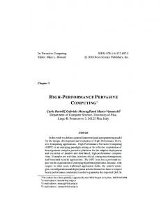
2 Background 2.1 Field-Programmable Gate Arrays (FPGAs) 2.1.1 FPGA Architecture FPGAs are generally regarded as a middle-ground between ASICs and general-purpose processors. This notion comes from the reconfigurable nature of these devices, making them more flexible than ASICs (at the cost of lower area and power efficiency) and more power efficient than general-purpose processors (at the cost of lower flexibility and more complex programming). Even though, deep down, FPGAs have a fixed architecture, they are largely composed of SRAM cells arranged in form of Loop-Up Tables (LUT), a plethora of registers, and programmable routing. Because of this, these devices can be rapidly reconfigured to implement different logic, just by changing the content of the LUTs and the routing configuration. Apart from the soft-logic LUTs, modern FPGAs also include hard-logic components such as Digital Signal Processors (DSP), large memory blocks (Block RAMs) and different I/O controllers (DDR, PCI-E, network, etc.). These components implement specialized logic that would otherwise take up too much space if implemented using LUTs.
ALM
ALM
ALM
DSP DSP DSP DSP
Transceiver Channels, Transceiver and PCI-E Controller
ALM
ALM
ALM
ALM
ALM
ALM
ALM
ALM
ALM
ALM
ALM
ALM
ALM
ALM
ALM
ALM
ALM
ALM
ALM
ALM
ALM
ALM
ALM
ALM
ALM
ALM
Figure 2-1 Intel Arria 10 FPGA architecture
6
ALM
ALM
ALM
ALM
ALM
ALM
ALM
ALM
ALM
ALM
ALM
ALM
ALM
ALM
ALM
ALM
Transceiver Channels, Transceiver and PCI-E Controller
ALM
ALM
Block RAM
ALM
ALM
ALM
Block RAM
ALM
ALM
ALM
Block RAM
ALM
ALM
ALM
Block RAM
ALM
ALM
ALM
Block RAM
ALM
ALM
DSP
ALM
ALM
DSP
ALM
ALM
DSP
ALM
ALM
DSP
ALM
ALM
DSP
ALM
ALM
Memory Controller, GPI/O and PLL
ALM
Block RAM
ALM
ALM
Block RAM
ALM
ALM
Block RAM
ALM
ALM
Block RAM
ALM
DSP
ALM
Block RAM
Fig. 2-1 shows the architecture of the Intel Arria 10 FPGA [14]. In this FPGA, the softlogic consists of Adaptive Logic Modules (ALM), and the hard-logic consists of DSPs, Block RAMs, multiple controllers, Transceivers and Phase-Locked Loops (PLL).
In the Arria 10 FPGA, each ALM consists of multiple-input LUTs, adders and carry logic, and registers (Flip-Flops). The internal architecture of the ALMs in the Arria 10 FPGA is depicted in Fig. 2-2. Each Adaptive LUT is capable of implementing multiple combinations of different functions including one 6-input function, two 5-input functions with two shared inputs, two 4-input functions with independent inputs, etc.
Figure 2-2 Intel Arria 10 ALM architecture; combined from Fig. 5 in [14] and Fig. 7 in [15]
Fig. 2-3 shows the block diagram of the DSPs in the Intel Arria 10 FPGA. Each of these DSPs is capable of implementing an IEEE-754-compliant single-precision floating-point addition (FADD), multiplication (FMUL), or Fused Multiply and Add (FMA) operation, or one 27-bit-by-27-bit integer or fixed-point multiplication. Furthermore, multiple DSPs can be chained to implement dot products or other complex operations.
Figure 2-3 Intel Arria 10 DSP architecture; taken from Fig. 27 in [15]
Finally, each Block RAM in the Intel Arria 10 device, called an M20K block, is capable of storing a maximum of 20 Kbits of data. Each block has two ports that operate independently, 7
and can satisfy one read and one write operation simultaneously. Data can be stored in each block with a maximum width of 40 bits, in which case the address size will be 9 bits (512 addresses). Apart from implementing multiple-ported RAM or ROMs, each M20K can also be used to implement First-In First-Out buffers (FIFO) or shift registers. Multiple M20K blocks can also be chained to implemented larger buffers.
2.1.2 FPGA Synthesis Traditionally, to create an FPGA design, the application is described using a Hardware Description Language (HDL) like Verilog or VHDL, and then multiple steps are carried out until an FPGA bitstream is created. First, the hardware description is synthesized into a netlist. All coding errors are determined in this step. In the next step, the mapping process maps all functions in the netlist to functions that are available as hard-logic on the FPGA; any other function will be implemented using soft-logic (LUTs). After that, the placement process determines which of the multiple instances of each function on the FPGA should be used for implementing the functions that are required by the design. If a design requires more instances of a specific function than are available on the FPGA, placement will fail. In the next step, the routing process will determine which routing resources are used and how they are connected so that all functions are correctly connected to each other and all timing constraints are met. Since routing resources are limited, routing could also fail in case of routing congestion. Finally, the FPGA bitstream is generated. The bitstream is generally transferred to the FPGA using JTAG to implement the synthesized design on the hardware. This chain of operations is the equivalent of compilation for software programs, and all this functionality is provided by the FPGA manufacturers’ tools. In case of Intel, these functions are provided by Intel Quartus Prime Software. For the Intel Stratix V FPGA, total synthesis time is typically 3 to 5 hours but can reach up to 8 hours, while for the larger Arria 10 device it is typically 8 to 12 hours but can take over a day for very large designs that suffer from severe routing congestion.
2.2 OpenCL Programming Language OpenCL [16] is an open-source and royalty-free standard for programming heterogeneous systems in a host/device fashion. An OpenCL-based application can be split into two separate parts: one is the host code that executes on the host CPU and can be written in any programing language as long as a compatible compiler exists, and the other is a C-based device code that is more commonly called the kernel code. OpenCL provides the necessary APIs for controlling the accelerator and communicating between the host processor and the accelerator. This programming language can be considered as a device-agnostic alternative to the NVIDIA CUDA programming language. The typical flow of operation in OpenCL is that first, all necessary data is allocated in host memory. Then, this data is transferred to the device memory using the respective OpenCL functions. In the next step, the kernel is loaded and executed on the device, where inputs are read from and outputs are written to the device memory. Finally, output data is transferred from the device memory to the host. 8
2.2.1 OpenCL Threading Model In OpenCL, each thread is called a work-item and multiple work-items are grouped to form a work-group. To execute an application, the thread space is distributed over multiple workgroups. Within each work-group, work-items are synchronized using barriers and data can be shared between the work-items using the fast on-chip local memory. However, the only way to share data between different work-groups is through the slow off-chip memory. The number of work-items in a work-group is called the local work size, and the total number of work-items necessary to fully execute an application is called the global work size. Work-items and workgroups can be arranged in multiple dimensions, up to three, in an index space called an NDRange.
2.2.2 OpenCL Memory Model In OpenCL, multiple memory types are defined: Global: This memory space resides on the device off-chip (external) memory and is generally the largest (up to a couple Gigabytes) but slowest memory that exists on an OpenCLcapable accelerator. The content of this memory space is visible to all work-items of all workgroups. Global memory consistency is only guaranteed after a kernel is executed completely. Local: This memory space resides on the on-chip memory of the OpenCL device and can be used to share data between the work-items within a work-group. Each work-group has its own local memory space, and the local memory space of a work-group is not visible to other work-groups. The total amount of local memory available on OpenCL accelerators is typically a few to a couple Megabytes. Local memory consistency is only guaranteed at barriers. Constant: This memory space resides on device external memory; however, this is a readonly memory space and is generally cached in device on-chip memory for faster access. Private: Any work-item-specific buffer or array is of this memory type. Private data generally resides on the fast device registers; however, due to very limited size (a few hundred Kilobytes per device), data stored in this memory space can leak to global memory, incurring a large performance penalty.
2.3 Intel FPGA SDK for OpenCL Intel FPGA SDK for OpenCL provides the necessary APIs and run-time to program and use PCI-E-attached or System-on-Chip (SoC) FPGAs similar to a GPU or other accelerators. The necessary IP Cores to communicate between the FPGA, external DDR memory, and PCIE, alongside with necessary PCI-E and DMA drivers for communication between the host and the FPGA are also provided by the board manufacturers in form of a Board Support Package (BSP). This relieves the programmer from the burden of having to manually set up the IP Cores and create the drives, as is done with traditional HDL-based FPGA designs. Some BSPs also provide the possibility to send and receive data using FPGA on-board network ports.
9
2.3.1 Intel FPGA SDK for OpenCL Flow Fig. 2-4 shows the flow of Intel FPGA SDK for OpenCL (formerly Altera SDK for OpenCL) to compile the host code and convert the kernel code to an FPGA-compatible bitstream. C/C++ Compiler & Intel OpenCL Runtime
Host code (.c/.cpp)
Host Binary Execution on FPGA
Kernel code (.cl)
AOC
LLVM IR
AOC
Verilog
FPGA Bitstream (.aocx)
Figure 2-4 Intel FPGA SDK for OpenCL flow; AOC is Intel FPGA SDK for OpenCL Offline Compiler
Unlike CPUs and GPUs, run-time compilation of OpenCL kernels is not possible for FPGAs due to very long placement and routing time. Hence, the OpenCL kernel needs to be compiled offline into an FPGA bitstream, and then loaded at run-time by the host code to reprogram the FPGA and execute the application.
2.3.2 NDRange Programming Model on FPGAs GPUs typically consist of a set of coarse-grained processing units (called Compute Units in AMD GPUs and Streaming Multiprocessors in NVIDIA GPUs), with each such unit containing a fixed number of fine-grained shader processors and a fixed amount of scratchpad memory and L1 cache. In the NDRange programming model, a work-group is generally mapped to one of the coarse-grained units, and each work-item is mapped to one of the finegrained shared processors. However, the aforementioned decomposition to coarse and finegrained units does not exists on FPGAs. By default, using the NDRange programming model on FPGAs will not result in thread-level parallelism and instead, the compiler will generate one compute unit implemented as a deep pipeline, with all work-items from all work-groups executing on that pipeline. Each region between two barriers in an NDRange kernel will be mapped to a separate pipeline, with each pipeline being flushed at the barrier. The compiler also automatically performs work-group pipelining, allowing multiple work-groups to be inflight in the same compute unit simultaneously to maximize the efficiency of all the pipelines in the compute unit, at the cost of higher Block RAM usage. Fig. 2-5 a) shows how two consecutive threads/work-items are pipelined with a distance from each other, called the Initiation Interval (II). The initiation interval is adjusted at run-time by the run-time scheduler that the compiler implements on the FPGA to minimize pipeline stalls and maximize pipeline efficiency. Intel FPGA SDK for OpenCL provides a SIMD attribute for the NDRange programming model that allows achieving work-item-level parallelism on the FPGA. Using this attributes, the pipeline is widened and pipeline stages are replicated so that multiple work-items can be 10
t
a)
Dependency
t+1
Barrier
issued in parallel by the scheduler in a compute unit. This programming model also provide the possibly to replicate the compute unit so that work-group-level parallelism can be achieved. Mixing SIMD and compute unit replication allows the programmer to achieve a GPU-like architecture on an FPGA, with the compute units acting as the coarse-grained processing units, and each set of the vectorized pipeline stages acting as a fine-grained unit.
i+1 i
b)
Figure 2-5 Pipeline generation for (a) NDRange and (b) Single Work-item kernels
2.3.3 Single Work-item Programming Model on FPGAs Apart from the NDRange model, Intel FPGA SDK for OpenCL also provides another programming model called the Single Work-item model. In the model, the entire kernel is executed by one work-item and instead, loop iterations are pipelined to achieve high performance. When this programming model is used, each set of nested loops in the kernel is mapped to a separate pipeline by the compiler. Fig. 2-5 b) depicts how two consecutive iterations of a loop are pipelined one after another. Using this model, no run-time scheduler will be created in the hardware anymore and instead, iteration scheduling is static and initiation interval is determined at compile-time depending on loop-carried and memory load/store dependencies. Iteration-level parallelization in form of vectorization can be achieved in this programming model by loop unrolling. Fig. 2-6 a) shows a basic example of an NDRange kernel and b) shows its equivalent Single Work-item kernel. Converting an NDRange kernel to Single Work-item can be done by wrapping the NDRange kernel in a for loop from zero to global work size in every dimension.
2.3.4 OpenCL Memory Types on FPGAs Using Intel FPGA SDK for OpenCL, OpenCL global memory resides on the FPGA external memory, which is usually a few banks of DDR3 or DDR4 memory. OpenCL local and private memory, depending on the size and access pattern of the buffer, will be implemented using registers or Block RAMs. Finally, constant memory is also implemented using Block RAMs with a fixed size that can be controlled using a compilation argument.
11
__kernel void ndrange(__global float* a, __global float* b) { int i = get_global_id(0); a[i] = b[i]; } a) __kernel void single_wi(__global float* a, __global float* b, int global_size) { for (int i = 0; i < global_size; i++) { a[i] = b[i]; } } b)
Figure 2-6 NDRange (a) vs. Single Work-item (b) code example
12
3 General Performance Model and Optimizations for FPGAs In this chapter, we will discuss our general performance model for FPGAs starting from a single-pipeline model and then extending it for data parallelism. Then, we outline the difference between the two programing models available in Intel FPGA SDK for OpenCL based on this model. In the next step, we discuss multiple HLS-based optimization techniques for FPGAs ranging from basic compiler-assisted optimizations to advanced manual optimizations, and explain how each relates to our model. The contents of this chapter have been partially published in [17].
3.1 General Performance Model 3.1.1 Single-pipeline Model For a given pipeline with a depth of P, a loop trip count of L (i.e. number of inputs) and an initiation interval of II, the total number of clock cycles to finish computation is: 𝑇𝑇𝑐𝑐𝑐𝑐𝑐𝑐𝑐𝑐𝑐𝑐 = 𝑃𝑃 + 𝐼𝐼𝐼𝐼 × (𝐿𝐿 − 1)
(3-1)
Here, P cycles are required until the pipeline is filled and the first output is generated, and after that, a new output is generated every II cycles. To convert this value to time, we have: 𝑇𝑇𝑠𝑠𝑠𝑠𝑠𝑠𝑠𝑠𝑠𝑠𝑠𝑠𝑠𝑠 =
𝑇𝑇𝑐𝑐𝑐𝑐𝑐𝑐𝑐𝑐𝑐𝑐 𝑃𝑃 + 𝐼𝐼𝐼𝐼 × (𝐿𝐿 − 1) = 𝑓𝑓𝑚𝑚𝑚𝑚𝑚𝑚 𝑓𝑓𝑚𝑚𝑚𝑚𝑚𝑚
(3-2)
In Eq. (3-2), 𝑓𝑓𝑚𝑚𝑚𝑚𝑚𝑚 is the operating frequency of the FPGA that is determined after placement and routing and is typically between 150 to 350 MHz on Intel Stratix V and Arria 10 devices. Among the parameters in Eq. (3-2), P is controlled by the compiler; however, as a general rule of thumb, simpler code will result in a shorter pipeline and lower P. L is also application-dependent and cannot be directly controlled by the user. 𝑓𝑓𝑚𝑚𝑚𝑚𝑚𝑚 is also generally a function of circuit complexity and size. Loop-carried dependencies and feedbacks in the design will adversely affect 𝑓𝑓𝑚𝑚𝑚𝑚𝑚𝑚 . Moreover, the bigger the design is and the closer utilization of each resource is to 100%, the more 𝑓𝑓𝑚𝑚𝑚𝑚𝑚𝑚 will be lowered due to placement and routing complications. In Section 3.2.4.4, we will show an advanced optimization technique that can significantly improve 𝑓𝑓𝑚𝑚𝑚𝑚𝑚𝑚 in Single Work-item kernel. The only remaining parameter is II. This parameter is the one that can be most directly influenced by the programmer and hence, most of the performance optimization effort will be spent on improving this parameter. II is influenced by multiple factors: loop-carried dependencies, shared on-chip resources like shared ports to local memory buffers implemented as multi-ported RAM/ROM, and accesses to/from external memory and on-chip channels since they can be stalled. These 13
sources can be split into two groups: sources that affect compile-time initiation interval (𝐼𝐼𝐼𝐼𝑐𝑐 ), and sources that affect run-time initiation interval (𝐼𝐼𝐼𝐼𝑟𝑟 ). For Single Work-item kernels, the effect of loop-carried dependencies and shared on-chip resources is determined at compiletime and 𝐼𝐼𝐼𝐼𝑐𝑐 is adjusted accordingly. In NDRange kernels, loops are not pipelined and hence, no such analysis is done and we can assume 𝐼𝐼𝐼𝐼𝑐𝑐 = 1. However, in both kernel types, accesses to external memory and channels will still influence 𝐼𝐼𝐼𝐼𝑟𝑟 . By default, the compiler inserts enough stages in the pipeline to hide the minimum latency of these operations, and accesses that take longer at run-time result in a pipeline stall. To estimate compile-time initiation interval (𝐼𝐼𝐼𝐼𝑐𝑐 ), we consider each kernel type separately (Fig. 3-1): • Single Work-item kernels: 𝐼𝐼𝐼𝐼𝑐𝑐 in this case depends on the number of stall cycles per iteration (𝑁𝑁𝑑𝑑 ) determined by the compiler and will be equal to 𝑁𝑁𝑑𝑑 + 1. Hence, Eq. (3-1) transforms into: 𝑇𝑇𝑐𝑐𝑐𝑐𝑐𝑐𝑐𝑐𝑐𝑐 = 𝑃𝑃 + (𝑁𝑁𝑑𝑑 + 1) × (𝐿𝐿 − 1)
(3-3)
• NDRange kernels: In these kernels, even though we can assume 𝐼𝐼𝐼𝐼𝑐𝑐 = 1, we need to take the overhead of barriers into account. Total run time for an NDRange kernel with 𝑁𝑁𝑏𝑏 barriers is: 𝑁𝑁𝑏𝑏
𝑁𝑁𝑏𝑏
𝑖𝑖=0
𝑖𝑖=0
𝑇𝑇𝑐𝑐𝑐𝑐𝑐𝑐𝑐𝑐𝑐𝑐 = �(𝑃𝑃𝑖𝑖 + 𝐿𝐿𝑖𝑖 − 1) = �� 𝑃𝑃𝑖𝑖 � + (𝑁𝑁𝑏𝑏 + 1) × (𝐿𝐿 − 1) = 𝑃𝑃 + (𝑁𝑁𝑏𝑏 + 1) × (𝐿𝐿 − 1)
(3-4)
In Eq. (3-4), 𝑃𝑃𝑖𝑖 and 𝐿𝐿𝑖𝑖 show the pipeline length and number of inputs (work-items) for each pipeline in an NDRange kernel. Since the number of work-items is fixed per kernel, 𝐿𝐿𝑖𝑖 for every pipeline is the same and equal to L. Furthermore, we will call the accumulated length of all the pipelines, P. After simplifying the equation, we reach a statement that is very similar to Eq. (3-3). In practice, the number of barriers in an NDRange kernel plays a similar role to that of stalls inserted in the pipeline due to dependencies in a Single Work-item kernel, and we can assume 𝑰𝑰𝑰𝑰𝒄𝒄 is equal to (𝑵𝑵𝒃𝒃 + 𝟏𝟏) instead of one. L-1
DDR
t+1
Barrier
II
t
a)
P1
P2
II DDR
Dependency
L-1
i+1
i
b)
P
Figure 3-1 NDRange (a) vs. Single Work-item (b) pipeline model
14
To take the effect of external memory accesses into account and estimate run-time initiation interval (𝐼𝐼𝐼𝐼𝑟𝑟 ), we use a simple model for external memory. For 𝑁𝑁𝑚𝑚 bytes read from and written to external memory per cycle and an external memory bandwidth per clock cycle of BW, we have: 𝐼𝐼𝐼𝐼𝑟𝑟 >
𝑁𝑁𝑚𝑚 𝐵𝐵𝐵𝐵
(3-5)
Here, BW is determined by the specifications of the external memory on the FPGA board. Furthermore, since our model is simplified and does not take coalescing, alignment and contention from different external memory accesses into account, the right-hand size of (3-5) only shows the minimum 𝐼𝐼𝐼𝐼𝑟𝑟 . Putting everything together, we have:
𝑁𝑁 + 1 𝑁𝑁𝑚𝑚 𝐼𝐼𝐼𝐼 > max(𝐼𝐼𝐼𝐼𝑐𝑐 , 𝐼𝐼𝐼𝐼𝑟𝑟 ) ⇒ 𝐼𝐼𝐼𝐼 > max �� 𝑑𝑑 , � 𝑁𝑁𝑏𝑏 + 1 𝐵𝐵𝐵𝐵
(3-6)
We ignore the role of stalls caused by on-chip channels here since if the channels are deep enough and the rate of channel reads and writes is similar, channel stalls will be very rare.
3.1.2 Extension for Data Parallelism To extend our model for cases where data parallelism in form of loop unrolling, SIMD or compute unit replication is employed with a degree of parallelism of 𝑁𝑁𝑝𝑝 (Fig. 3-2), run time can be calculated as: 𝑇𝑇𝑐𝑐𝑐𝑐𝑐𝑐𝑐𝑐𝑐𝑐 = 𝑃𝑃′ + 𝐼𝐼𝐼𝐼 ×
�𝐿𝐿 − 𝑁𝑁𝑝𝑝 � 𝑁𝑁𝑝𝑝
(3-7)
In this case, the pipeline depth generally increases compared to the case where data parallelism is not present. However, for an 𝐿𝐿 ≫ 𝑃𝑃′ , Eq. (3-7) points to a performance improvement of nearly 𝑁𝑁𝑝𝑝 times since the loop trip count is effectively reduced by a factor of 𝑁𝑁𝑝𝑝 . On the other hand, data parallelism also increases memory pressure by a factor of 𝑁𝑁𝑝𝑝 and hence, II will be affected as follow: 𝑁𝑁𝑑𝑑 + 1 𝑁𝑁𝑚𝑚 × 𝑁𝑁𝑝𝑝 𝐼𝐼𝐼𝐼 > max �� , � 𝐵𝐵𝐵𝐵 𝑁𝑁𝑏𝑏 + 1
(3-8)
Based on Eq. (3-7) and (3-8), when data parallelism is present, assuming that sufficient external memory bandwidth is available, performance will improve by a factor close to 𝑁𝑁𝑝𝑝 .
15
L-Np ― Np
i+3 II
DDR
i+2
i+1
Np
i P′
Figure 3-2 Pipeline model for data parallelism
3.1.3 General Optimization Guidelines Based on our model, we conclude that to improve performance for an HLS-based design on FPGAs, our optimization effort should be focused on: • • • •
Reducing stalls (𝑁𝑁𝑑𝑑 ) in Single Work-item kernels Reducing number of barriers (𝑁𝑁𝑏𝑏 ) in NDRange kernels Reducing external memory accesses (𝑁𝑁𝑚𝑚 ) Increasing data parallelism (𝑁𝑁𝑝𝑝 )
3.1.4 Single Work-item vs. NDRange Kernels
One important factor in OpenCL-based designs for Intel FPGAs is to decide whether to use Single Work-item or NDRange kernels. Fig. 3-3 shows the most important difference between these two kernel types. Even though we explained earlier that in NDRange kernels, threads are pipelined and no thread-level parallelism exists by default, the programming model itself assumes that threads are running in parallel and hence, the issue distance between the threads neither appears nor can be influenced in the kernel code. Due to this reason, local memorybased optimizations in NDRange kernels require barriers since there is no direct way of transferring data between threads in an NDRange kernel. In contrast, in Single Work-item kernels there is a minimum distance of one clock cycle between loop iterations. It is possible to take advantage of this issue distance to directly transfer data from one loop iteration to another, especially to resolve loop-carried dependencies. This type of communication can be realized using single-cycle reads and writes from and to the plethora of registers that are available in every FPGA. Based on this analysis, we conclude that in Single Work-item kernels, it might be possible to fully resolve iteration dependencies and reduce 𝑵𝑵𝒅𝒅 to zero; however, in NDRange kernels where local memory-based optimizations are employed, barriers will always be required and 𝑵𝑵𝒃𝒃 will never become zero. Hence, based on Eq. (3-6), a Single Work-item kernel can potentially have a lower effective 𝑰𝑰𝑰𝑰𝒄𝒄 compared to its NDRange equivalent. This shows the clear advantage of the Single Work-item programming model compared to NDRange for FPGAs. Moreover, shift registers, which are an efficient storage type on FPGAs, can only be inferred in Single Work-item kernels (Section 3.2.4.1). 16
Barrier
t+2 t+1
a)
t i+2 i+1
b)
i Figure 3-3 Data sharing in (a) NDRange and (b) Single Work-item kernels
On the other hand, NDRange kernels also have their own advantages in certain applications. In cases where an 𝐼𝐼𝐼𝐼𝑐𝑐 = 1 can be achieved, a Single Work-item kernel is preferred. However, for cases where this cannot be achieved, NDRange kernels could potentially achieve better performance. This difference stems from the fact that 𝐼𝐼𝐼𝐼𝑐𝑐 in Single Work-item kernels is static and is determined based on the worst case loop-carried or load/store dependency at compiletime, while in NDRange kernels, initiation interval is determined at run-time by the thread scheduler. Because of this, in cases where 𝐼𝐼𝐼𝐼𝑐𝑐 = 1 cannot be achieved in the Single Work-item implementation of an application, the thread scheduler in the NDRange equivalent might be able to achieve a lower average initiation interval by reordering the threads at run-time, compared to the Single Work-item equivalent with a fixed worst-case initiation interval. In summary, the following points should be taken into account to decide whether to choose NDRange kernels for a design, or Single Work-item kernels: • Applications with non-fully-pipelineable loops (e.g. loops with variable exit conditions or complex loop-carried/load/store dependencies) or random external memory accesses can potentially perform better using the NDRange programming model • Every other application will potentially perform better using the Single Work-item programming model, especially if registers or shift registers can be used to efficiently resolve loop-carried dependencies.
3.2 HLS-based Optimization Techniques for FPGAs In this section, we will discuss multiple different optimization techniques for HLS-based designs on FPGAs, ranging from basic compiler-assisted optimizations to advanced manual optimizations that require significant code refactoring. The basic optimizations discussed here are techniques that are introduced in Intel’s OpenCL documents [18, 19], while most of the advanced ones are not directly discussed in these documents. We only discuss kernel optimization here. Some of the discussed optimizations are only applicable to one kernel type; “NDR” and “SWI” are used to mark optimizations specific to NDRange and Single Work-item kernels, respectively. Optimizations applicable to both have been marked as “BOTH”.
17
3.2.1 Basic Compiler-assisted Optimizations 3.2.1.1 restrict keyword (BOTH): The restrict keyword can be added to global pointers in the kernel to prevent the compiler from assuming false pointer aliasing. This optimization usually has little to no effect in NDRange kernels; however, it is a crucial optimization in Single Work-item kernels, which, if not used, can result in very high initiation interval or even full sequential execution. This optimization can improve performance by reducing 𝑁𝑁𝑑𝑑 , and consequently, reducing 𝐼𝐼𝐼𝐼𝑐𝑐 . 3.2.1.2 ivdep pragma (SWI):
The ivdep pragma is used to prevent the compiler from assuming false load/store dependencies on global buffers. This pragma in only applicable to Single Work-item kernels and should be used with extreme care since incorrect usage can result in incorrect output. Even though this pragma can also be used for local buffers, it is very rare for the compiler to detect a false dependency on such buffers. This optimization can improve performance by reducing 𝑁𝑁𝑑𝑑 , and consequently, reducing 𝐼𝐼𝐼𝐼𝑐𝑐 . 3.2.1.3 Removing thread scheduler (SWI):
The run-time thread scheduler is only needed for NDRange kernels and is not required for Single Work-item kernels. However, in cases where a Single Work-item kernel is launched from the host using the clEnqueueNDRangeKernel() function, the scheduler is required for correct kernel launch. On the other hand, for cases where the clEnqueueTask() function is used to launch such kernel, a compiler-provided attribute can be used to remove the scheduler to save some FPGA resources. The only downside of this optimization is that clEnqueueTask() has been deprecated in OpenCL 2.0. This optimization does not directly affect performance and only reduces area utilization by a small amount. 3.2.1.4 Setting work-group size (NDR): Intel FPGA SDK for OpenCL Offline Compiler provides attributes for NDRange kernels to set the exact or maximum kernel work-group size. This allows the compiler to minimize the size of local memory buffers based on the user-supplied information. Furthermore, the SIMD attribute can only be used if the exact work-group size is set by the programmer. If this information is not supplied, the compiler will assume a default work-group size of 256, potentially wasting valuable Block RAM resources if a smaller work-group size is used at runtime. Using this attribute comes at the cost of kernel execution failure if the run-time-provided work-group size supplied by the host does not align with the information supplied to the compiler in the kernel. This optimization does not have a direct effect on performance; however, the area reduction from this optimization can potentially allow performance improvement by using more data parallelism or larger block size. 3.2.1.5 Data parallelism (BOTH): For NDRange kernels, data parallelism can be achieved by using the SIMD or num_compute_units() attributes. SIMD will provide work-item-level parallelism, while 18
num_compute_units() provides work-group-level parallelism. Using SIMD has a lower area overhead since it does not require full compute unit replication, and only the pipeline stages are replicated so that multiple work-items can be issued and processed in parallel. Furthermore, internal and external memory accesses can be coalesced in this case, allowing higher internal and external memory bandwidth with minimum amount of contention and area overhead. However, using this attribute is subject to multiple limitations. First, the SIMD length must be a power of two up to maximum of 16 (which is an artificial compiler limitation since any arbitrary SIMD length should be implementable on an FPGA). Second, no thread-id-dependent branches should exist in the code. Finally, work-group size should be set by the programmer (Section 3.2.1.4) and be divisible by SIMD length. Using num_compute_units() has neither of these limitations; however, it comes at the cost of higher area overhead due to complete compute unit replication, and lower memory throughput compared to SIMD due to multiple narrow accesses competing for the external memory bandwidth instead of one wide coalesced access. For Single Work-item kernels, a SIMD-like effect can be achieved using loop unrolling, without any of the limitations that exist for using SIMD. However, area overhead of loop unrolling will be minimized when a loop with a trip count known at compile-time is either fully unrolled, or partially unrolled with a factor that the trip count is divisible by. As explained in Section 3.1.2, these techniques can improve performance by a factor close to the degree of parallelism if sufficient external memory bandwidth is available. A direct effect of data parallelism in form of SIMD for NDRange kernels and unrolling for Single Work-item kernels is that external memory accesses which are consecutive in the dimension that SIMD or unrolling is applied on will be coalesced by the compiler into wider accesses at compile-time, allowing better utilization of the external memory bandwidth. Compared to having multiple narrow accesses per iteration to external memory, a few wide accesses result in much less contention on the memory bus and much more efficient utilization of the external memory bandwidth. However, using SIMD and unrolling over non-consecutive external memory accesses could instead lead to many narrow access ports and lower performance due to large amount of contention on the memory buss. Using either of these techniques also has a similar effect on local memory buffers. Using SIMD and unrolling over consecutive local memory accesses leads to access coalescing and data interleaving with minimal area overhead, while applying these over non-consecutive accesses will result in high replication factors for local buffers and waste of FPGA area.
3.2.2 Basic Manual Optimizations 3.2.2.1 Shift register for floating-point reduction (SWI): On most FPGAs, floating-point operations cannot be performed in one clock cycle (unless at the cost of extremely low operating frequency). Because of this, for floating-point reduction operations where the same variable appears on both sides of the assignment (i.e. the reduction variable), data dependency on this variable prevents pipelining with an initiation interval of one and instead, the initiation interval equals the latency of the floating-point operation (e.g. 8 clocks for floating-point addition on Intel Stratix V). As suggested in Intel’s documents [18], this dependency can be eliminated by inferring a shift register with a size equal to the latency 19
of the floating-point operation. In this case, in every iteration data is read form the head of the shift register and written to its tail, with the shift register being shifted afterwards. The use of an array of reduction variables instead of just one such variable effectively eliminates the dependency, reducing 𝑁𝑁𝑑𝑑 to zero and consequently, reducing 𝐼𝐼𝐼𝐼𝑐𝑐 to one for the reduction loop. To obtain the final output, another reduction is needed on the content of the shift register. It is worth noting that unlike what is suggested in [18], the size of the shift register does not need to be one index bigger than the latency of the reduction operation and in our experience, even if the size is exactly equal to the latency of the operation, the dependency can be eliminated without lowering operating frequency. The transformation from an unoptimized floating-point reduction to optimized version with shift register is shown in Fig. 3-4. float final_sum = 0.0f; for (int i = 0; i < size; i++) { final_sum += in[i]; }
a) #define FADD_LATENCY
8
// latency of floating-point operation
// shift register definition and initialization float shift_reg[FADD_LATENCY] = {0.0f}, final_sum = 0.0f; for (int i = 0; i < size; i++) { // add and write to shift register shift_reg[FADD_LATENCY - 1] = shift_reg[0] + in[i]; // shifting #pragma unroll for (int j = 0; j < FADD_LATENCY - 1; j++) { shift_reg[j] = shift_reg[j + 1]; } } //final reduction #pragma unroll for (int i = 0; i < FADD_LATENCY; i++) { final_sum += shift_reg[i]; }
b) Figure 3-4 Shift register optimization for floating-point reduction
This optimization is usually not enough to provide good performance on its own and it needs to be followed by data parallelism (Section 3.2.1.5). Even though the resulting optimized loop can be partially unrolled by using the unroll pragma to further improve the performance, doing so will break the shift register optimization and requires that the size of the shift register is increased further to accommodate for the unrolling. With large unroll factors, this method can result in large area overhead to implement the shift register. As a much better optimized alternative, it is possible to add data parallelism to the optimized code from 3-4 b) by performing manual unrolling as depicted in Fig. 3-5. In this case, the original loop is split into 20
two loops, with the inner loop being fully unrolled and having a trip count equal to the unroll factor, and the exit condition of the outer loop being adjusted accordingly. In this case, the shift register optimization is not required for the inner loop since full unrolling effectively eliminates the dependency on the reduction variable, and it only needs to be applied to the outer loop. This method makes it possible to achieve efficient data parallelism alongside with the shift register optimization for floating-point reduction, without needing to increase the size of the shift register. #define FADD_LATENCY #define UNROLL
8 // latency of floating-point operation 16 // unroll factor
// shift register definition and initialization float shift_reg[FADD_LATENCY] = {0.0f}, final_sum = 0.0f; // loop exit condition calculation int exit = (size % UNROLL == 0) ? (size / UNROLL) : (size / UNROLL) + 1; for (int i = 0; i < exit; i++) { // unrolled addition float sum = 0.0f; #pragma unroll for (int j = 0; j < UNROLL; j++) { int index = i * UNROLL + j; sum += (index < size) ? in[index] : 0.0f; } // write to shift register shift_reg[FADD_LATENCY - 1] = shift_reg[0] + sum; // shifting #pragma unroll for (int j = 0; j < FADD_LATENCY - 1; j++) { shift_reg[j] = shift_reg[j + 1]; } } //final reduction #pragma unroll for (int i = 0; i < FADD_LATENCY; i++) { final_sum += shift_reg[i]; }
Figure 3-5 Optimized floating-point reduction with unrolling
As a final note, on the Intel Arria 10 FPGA, it is possible to use single-cycle floating-point accumulation and hence, the shift register optimization is not required on this FPGA. However, due to the requirements for correct inference of single-cycle accumulation by the compiler on Arria 10, it is required that data parallelism is implemented using the aforementioned method rather than applying partial unrolling directly to the reduction loop. 3.2.2.2 Calculating constants on host instead of kernel (BOTH): For cases where a value is calculated on the kernel and remains constant throughout the kernel execution, calculation of this constant can be moved to the host code to save FPGA area. This optimization is specifically useful in cases where calculation of a constant involves 21
complex mathematical functions (division, remainder, exponentiation, trigonometric functions, etc.) and could use a significant amount of FPGA area. This optimization does not directly lead to performance improvements; however, area savings from this optimization could allow more parallelism or higher 𝑓𝑓𝑚𝑚𝑚𝑚𝑚𝑚 .
3.2.2.3 Avoiding branches on global memory addresses and accesses (BOTH):
For cases where in a kernel, the external memory address that is accessed could change based on run-time variables, instead of choosing the correct address using branches, it is best if both accesses are performed and results are stored in temporary variables and instead, the correct output is chosen from the temporary variables. This will prevent dynamic addressing and potentially allow the compiler to coalesce accesses when SIMD or unrolling is used. A similar problem exists when a branch involves choosing a value from two different global memory addresses. Also in this case, moving the accesses out of the branch and storing their value in two temporary variables, and instead using the temporary variables in the branch could allow correct coalescing when SIMD or loop unrolling is used. Apart from the area saving due to lower number of ports going to external memory, this optimization could also improve performance by decreasing 𝑁𝑁𝑚𝑚 and consequently, reducing 𝐼𝐼𝐼𝐼𝑟𝑟 . However, for cases where SIMD or unrolling are not used and compile-time coalescing is not required, the best choice is to choose the correct address and only perform one access to global memory to minimize the number of access ports.
3.2.3 Advanced Compiler-assisted Optimizations 3.2.3.1 Manual external memory banking (BOTH): By default, Intel FPGA SDK for OpenCL Offline Compiler interleaves all the global buffers between the two (or more) DDR memory banks available on an FPGA board so that the bandwidth of all the banks is efficiently shared between all the buffers. In cases where multiple global buffers exist with different access rates, or a few narrow accesses to global memory exist in the kernel, this automatic interleaving achieves best memory performance. However, in our experience, for cases where only two wide global memory accesses (with or without some accompanying narrow ones) exist in the kernel, each to a different global buffer, this automatic interleaving does not perform optimally and disabling it can improve performance if the buffers are each pinned to a different memory bank. To achieve this, the kernel should be compiled with a specific compiler switch to disable automatic interleaving [19], and the global buffers in the host code should be created with an additional flag that allows the user to manually determine which buffer should reside on which memory bank. In this case, performance is improved by increasing the effective BW from Eq. (3-5), and consequently, reducing 𝐼𝐼𝐼𝐼𝑟𝑟 . Furthermore, for cases where multiple global memory types exist on the board (DDR, QDR, HBM, etc.), this technique can be used to manually allocate some of the global buffers on the non-default memory type(s). 3.2.3.2 Disabling cache (BOTH): By default, Intel FPGA SDK for OpenCL Offline Compiler generates a private cache for every global memory access in a kernel if it cannot determine the exact access pattern. This 22
cache is implemented using FPGA Block RAMs and is not shared between different accesses to the same global buffer. Despite its simplicity and small size (512 Kbits), this cache can be effective for designs that have good spatial locality that is not exploited by the programmer. However, in two cases this cache not only will not improve performance, but can potentially even reduce it: • In cases where random accesses exist in the kernel with minimal spatial locality, the cache hit-rate will be very low and hence, disabling it can improve performance by avoiding the overhead of the cache mechanism. The hit-rate of the cache can be determined by using Intel FPGA Dynamic Profiler for OpenCL. • In cases where data locality is manually exploited by the programmer by using on-chip memory, which will be the case for all well-optimized designs, the cache will not be required anymore and using it will only waste valuable Block RAM resources. In such cases, the cache can be disabled to save area. To selectively disable the cache for a global buffer, it can be falsely marked as volatile in the OpenCL kernel. To completely disable the cache for all global buffers in a kernel, “--optarg -nocaching” can be added to the kernel compilation parameters. In our experience, this cache is usually not created in NDRange kernels but it is nearly always created in Single Workitem. 3.2.3.3 Autorun kernels (SWI): Intel FPGA SDK for OpenCL provides a specific autorun attribute for Single Work-item kernels that do not have an interface to the host or the FPGA external memory but can communicate with other autorun or non-autorun kernels using on-chip channels [19]. This kernel type does not need to be invoked from the host and automatically launches as soon as the FPGA is programmed. Furthermore, the kernel is automatically restarted whenever it finishes execution. This type of kernel has two main use cases: • For designs in which data is sent and received directly via the FPGA on-board peripherals, and no interaction from the host is required, this kernel type can be used so that the FPGA can act as a standalone processor. This type of design is specifically useful for network-based processing where data is streamed in and out through the FPGA onboard network ports. • For streaming designs that require replication of a Single Work-item kernel, this attribute can be used alongside with the multi-dimensional version of the num_compute_units() attribute (different from the single-dimensional one used for NDRange kernels). In this case, a get_compute_id() function is supplied by the compiler that can be used to obtain the unique ID of each kernel copy at compile-time and then, each kernel copy can be customized using this ID. This attribute is specifically useful for streaming designs in form of multi-dimensional systolic array or single-dimensional ring architectures. Apart from the obvious area reduction duo to lack of interface to host and memory for this kernel type, in our experience, using this kernel type also results in efficient floorplanning and good scaling of operating frequency even with tens of kernel copies.
23
3.2.3.4 Flat compilation (BOTH): Using Intel FPGA SDK for OpenCL, the FPGA is automatically reprogrammed at run-time with the pre-compiled FPGA bitstream before kernel execution. On the Intel Stratix V device, this reconfiguration is performed using Configuration via Protocol (CvP) [20]. However, CvP update is not supported on the Intel Arria 10 device [21] and hence, the FPGA is reprogrammed at run-time using Partial Reconfiguration (PR) via PCI-E. In this case, the logic related to the OpenCL BSP is the static part of the design which resides on a fixed section of the FPGA and is never reconfigured. The rest of the FPGA area can be used by the OpenCL kernel, which acts as the dynamic part of the design and is reconfigured at run-time. Using PR for OpenCL on Arria 10 imposes extra placement and routing constraints on the design to ensure correct run-time reconfiguration; this comes at the cost of more placement and routing complications on this device and consequently, worse timing or even an outright unfittable or unrouteable design, especially when FPGA logic or Block RAM utilization is high. Furthermore, in our experience, run-time partial reconfiguration through PCI-E has a high failure rate, resulting in the program or even the OS crashing in many cases. To avoid these issues, the possibility of flat compilation on Arria 10 is also provided by the compiler, which disables PR and place and routes the BSP and the OpenCL kernel as one flat design. This eliminates all extra constraints for PR and allows the programmer to use the FPGA area more efficiently and achieve best timing. This compiler optimization can improve performance by both providing better area utilization efficiency for large designs that would have failed to fit or route with the PR flow, and also improving 𝑓𝑓𝑚𝑚𝑚𝑚𝑚𝑚 . However, using flat compilation comes at the cost of two shortcomings. One is the longer run-time reconfiguration time since the FPGA has to be reconfigured via JTAG instead of PCI-E (15-20 seconds vs. less than 5 seconds). The other is that since all clock constraints except for the kernel clock in the BSP are relaxed for flat compilation, other clocks like PCI-E and DDR might fail to meet timing and hence, the user has to try multiple seeds and manually check the timing report to make sure all timing constraints are met. In practice, we have seen that for large NDRange designs, it might not be possible to meet the timing constraints of the non-constrained clocks regardless of how many different seeds are tried. Hence, this optimization should be limited to highly-optimized Single Work-item designs and it is probably best to use the default PR flow for NDRange. 3.2.3.5 Target 𝒇𝒇𝒎𝒎𝒎𝒎𝒎𝒎 and seed sweep (BOTH):
By default, Intel FPGA SDK for OpenCL Offline Compiler balances pipeline stages in the design by inserting extra registers and FIFOs towards a target 𝑓𝑓𝑚𝑚𝑚𝑚𝑚𝑚 of 240 MHz. This target can be increased so that the compiler would insert more registers and FIFOs in the pipeline, potentially allowing a higher operating frequency, at the cost of higher logic and Block RAM utilization. This optimization is not viable for cases where logic and Block RAM utilization is already high, since the extra area usage could instead lead to more routing congestion and worse 𝑓𝑓𝑚𝑚𝑚𝑚𝑚𝑚 . Furthermore, careful attention is required when changing the target 𝑓𝑓𝑚𝑚𝑚𝑚𝑚𝑚 for Single Work-item kernels since if the target is set too high, the compiler might have to increase the initiation interval of some loops to achieve the target and this could instead result in performance slow-down despite higher operating frequency. The compiler also provides the possibility to change the placement and routing seed, which can result in better (or worse) 𝑓𝑓𝑚𝑚𝑚𝑚𝑚𝑚 , 24
at the cost of no extra area utilization. These two optimizations can be used as the last step of optimization to maximize 𝑓𝑓𝑚𝑚𝑚𝑚𝑚𝑚 for a given design by compiling multiple instances of the design, each with a different seed and 𝑓𝑓𝑚𝑚𝑚𝑚𝑚𝑚 target, and choosing the one with highest operating frequency.
3.2.4 Advanced Manual Optimizations 3.2.4.1 Shift register as local data storage (SWI): Each FPGA has a plethora of registers available that can be used for temporary data storage. The main advantage of registers over Block RAMs for data storage is that access latency to registers is one clock cycle, allowing efficient data sharing between loop iterations without increasing the loop initiation interval. However, since each ALM has a few registers, and chaining registers requires using FPGA routing resources, implementing large on-chip buffers using registers is not efficient. On the other hand, Block RAMs are suitable for implementing large on-chip buffers, but latency of dynamic access to Block RAMs is not one clock cycle and hence, reading from and writing to on-chip buffers implemented using Block RAMs in a loop can result in read-after-write dependencies and high initiation intervals. With all this, if certain requirements are met, large buffers can be implemented using Block RAMs with an access latency of one clock cycle: • All accesses to the buffer use static addresses that are known at compile-time • The content of the buffer is shifted once per loop iteration by a fixed amount This will result in inference of an FPGA-specific on-chip storage called a shift register (also called sliding window or line buffer in literature). Shift registers are suitable for applications that involve the point of computation being shifted over a regular grid, including but not limited to stencil computation, image filtering, and sequence alignment. Due to the above requirements, this on-chip storage type can only be described in Single Work-item kernels. Fig. 3-6 shows how a Block RAM is used to implement a shift register for 2D stencil computation. In this case, after an initial warm-up period to fill the shift register, all data points involved in the computation of the stencil reside in the shift register buffer at any given clock cycle. By incrementing the starting address of the buffer in the Block RAM, the center of the stencil is effectively shifted forward in the grid, while the relative distance of all neighbors from the starting address remains the same, allowing static addressing in a loop. Since static addressing does not require address decoding, and shifting the buffer forward only involves incrementing the starting address, accesses to shift registers can be done in one clock cycle. Shift registers are one of the most important architectural advantages of FPGAs compared to other hardware.
25
Starting Address
N
W
C
Starting Address
N
E Mapping to Block RAM
S
Write
W C E
S
Read
Read Read Read
Read
Figure 3-6 Shift register inference
The performance improvement of shift registers is two-fold: compared to using standard Block RAM-based buffers with dynamic access, using shift registers allows the programmer to avoid read-after-write dependencies, reducing 𝑁𝑁𝑑𝑑 to zero and 𝐼𝐼𝐼𝐼𝑐𝑐 to one. Furthermore, as shown in Fig. 3-6, a shift register can act as an efficient cache for neighboring cells in a grid, reducing redundant off-chip memory accesses (𝑁𝑁𝑚𝑚 ) and improving 𝐼𝐼𝐼𝐼𝑟𝑟 . 3.2.4.2 Reducing local memory accesses (BOTH):
Local memory-based optimizations are used on every hardware to improve performance by reducing accesses to the slower external memory and instead, storing and accessing frequentlyused data in the faster local memory. Due to limited amount of local memory available on each given device, careful attention is required to ensure only widely-used buffers reside in this memory type, and are replaced as soon as they are not required anymore. On CPUs, the cache hierarchy acts as local memory and is mostly hardware-managed; however, programming techniques such as loop tiling can help improve cache hit rate and performance. On modern GPUs, a limited set of registers, some scratchpad memory, and two levels of cache are available. The user-managed resources (registers and scratchpad) make up the smaller chunk of the local memory resources, while the larger chunk consisted of caches is again hardware-managed. On FPGAs, things are different: all local memory resources on FPGAs are user-managed and no explicit cache hierarchy exists. This makes careful utilization and configuration of local memory resources on these devices even more crucial. Apart from the size of local buffers, the number of accesses to such buffers also plays a crucial role in local memory usage on FPGAs. For small buffers implemented using registers, multiple read and write ports can be connected to the same buffer instance with small area overhead; however, as the number of accesses goes up, the fan-in and fan-out of the buffer also increase, resulting in routing compilations and lowered 𝑓𝑓𝑚𝑚𝑚𝑚𝑚𝑚 , or an outright unrouteable design. For larger buffers implemented using Block RAMs, whether in form of shift registers or multiported RAM/ROMs, since each Block RAM only has two physical ports, in most cases the buffer needs to be physically replicated on the FPGA to provide the necessary number of access ports for parallel non-stallable accesses to the buffer. For cases with an inefficient access pattern to local memory, this replication can easily result in exhaustion of Block RAM resources on the FPGA. If this happens, the compiler will then restart the compilation and instead shares Block RAM ports between multiple accesses so that replication factor, and 26
consequently, Block RAM utilization, is reduced and the design can fit. Needless to say, port sharing requires arbitration and results in stallable accesses, reducing performance by increasing 𝐼𝐼𝐼𝐼𝑟𝑟 in pretty much every case.
One compiler-assisted solution to reduce the Block RAM replication factor is to doublepump the Block RAMs. In this case, the number of ports to each Block RAM is effectively doubled since the Block RAM is driven with 2x the clock of the OpenCL kernel. However, correct communication between the OpenCL kernel and the Block RAMs in this case will require extra logic and since there is a physical limit for the operating frequency of Block RAMs (500-600 MHz on current devices), the maximum operating frequency of the OpenCL kernel will be limited to half of that limit (250-300 MHz). The compiler generally employs this technique by default; in fact, for cases where two or more writes to a specific local buffer exist in a kernel, since write ports need to be connected to all replicated instances of the buffer, there is no choice other than double-pumping the Block RAMs to achieve non-stallable accesses. However, the compiler also provides certain attributes for manual double-pumping and port sharing so that the programmer can also influence the compiler’s decisions in this case.
A more important method to reduce Block RAM replication factor is to reduce number of accesses to the buffer. This can be done by using temporary registers, or even transposing the local buffer or re-ordering nested loops to allow efficient access coalescing in presence of loop unrolling or SIMD. This optimization, apart from the obvious area reduction, can also allow reducing or completely removing stallable accesses to local memory buffers and improving performance by reducing 𝐼𝐼𝐼𝐼𝑟𝑟 . Fig. 3-7 a) shows a code snippet in which a local buffer implemented using Block RAMs is first initialized, and then a reduction operation is performed, with the output being stored in the local buffer. As is evident from the code snippet, one read port and two write ports are required to the temp buffer in this part of the kernel. These accesses alone will force the compiler into double-pumping the Block RAMs used to implement this buffer. Furthermore, the buffer will need to be replicated one extra time for every two reads from the buffer (two ports of each double-pumped Block RAM are connected to the write accesses and the remaining two ports can be used for reads). However, by moving the local buffer outside of the reduction loop and replacing it with a temporary register as is shown in Fig. 3-7 b), one read and one write are removed, eliminating the need for buffer replication if up to three reads from the buffer exist in the rest of the kernel, and avoiding the need for double-pumping in case of only one read from the buffer in the rest of the kernel.
27
__global float* a, b; __local float temp[M];
__global float* a, b; __local float temp[M];
for(int i = 0; i < M; i++) { temp[i] = 0; }
for(int i = 0; i < M; i++) { float reg = 0;
for(int i = 0; i < M; i++) { for(int j = 0; j < N; j++) { temp[i] += a[i] * b[j]; } }
for(int j = 0; j < N; j++) { reg += a[i] * b[j]; } temp[i] = reg; }
a)
b)
Figure 3-7 Reducing Block RAM replication by using temporary registers
Another case of reducing Block RAM replication is depicted in Fig. 3-8. In code snippet a), since the inner loop is unrolled on the higher dimension of the local buffer, the accesses to that buffer cannot be coalesced and hence, eight write ports are required to the buffer which results in port sharing. However, by transposing the buffer, i.e. swapping its dimensions as shown in b), this issue can be avoided. In the latter case, only one large coalesced write to the buffer will be required and hence, instead of replicating the buffer, the large write will be made possible by interleaving the buffer across multiple Block RAMs. In this case, for buffers that are small enough to fit in less than eight Block RAMs, eight Block RAMs will still be required to implement the buffer so that enough ports are available; however, for larger buffers, the overhead of interleaving will be minimal. It is worth noting that re-ordering the i and j loops will also result in correct access coalescing to the local temp buffer; however, it will break access coalescing to the global buffer a, significantly reducing external memory performance. __global float* a; __local float temp[N][M];
__global float* a; __local float temp[M][N];
for(int i = 0; i < M; i++) { #pragma unroll 8 for(int j = 0; j < N; j++) { temp[j][i] = a[i * COL + j]; } }
for(int i = 0; i < M; i++) { #pragma unroll 8 for(int j = 0; j < N; j++) { temp[i][j] = a[i * COL + j]; } }
a)
b)
Figure 3-8 Reducing Block RAM replication by transposing the buffer
3.2.4.3 Loop collapse (SWI): Multiply-nested loops are a recurring pattern in HPC applications. Having such loops incurs extra overhead on FPGAs since, relative to the depths of the loop nest, more registers and Block RAMs will be needed to store the state of the different variables in the loop nest. As an FPGAspecific optimization, loop nests can be collapsed into a single loop to avoid this extra area 28
overhead. Even though the same optimization is also regularly performed on OpenMP code running on CPUs, the goal of the optimization on CPUs and FPGAs is completely different. This conversion is shown in Fig. 3-9. for (int y = 0; y < M; y++) { for (int x = 0; x < N; x++) { compute(x,y); } }
int x = 0, y = 0; while (y != M) { compute(x,y); x++; if (x == N) { x = 0; y++; } }
a)
b) Figure 3-9 Loop collapse optimization
This optimization does not have a direct effect on performance; however, the area reduction resulting from this optimization can open up FPGA resources, providing room for extra parallelism or larger block size and consequently, higher performance. Furthermore, this optimization simplifies the pipeline and can result in lower pipeline latency (P). In the recent versions of Intel FPGA SDK for OpenCL, a new loop_coalesce pragma has been introduced that allows this optimization to be performed directly by the compiler. However, using this pragma is subject to certain limitations and does not work for all loop nests. Furthermore, the “exit condition optimization” which will be explained next is only possible after manual loop collapsing. 3.2.4.4 Exit condition optimization (SWI): Apart from the extra area overhead of multiply-nested loops on FPGAs, having such loops also has another disadvantage: since we want all loops in a loop nest to have an initiation interval of one to achieve maximum performance, the exit condition of all the loops in the loop nest need to be evaluated in one clock cycle. Since the exit conditions depend on each other, a long chain of comparisons and updates on the loop variables is created that will adversely affect the design critical path and reduce 𝑓𝑓𝑚𝑚𝑚𝑚𝑚𝑚 . In fact, in our experience, the design critical path of Single Work-item kernels that do not have loop-carried dependencies is nearly always located in the chain of functions required to determine the exit condition of the deepest loop nest in the kernel. Even though the “loop collapse” optimization introduced earlier reduces the loop nest to one loop, it does not change the loop exit condition. To improve this critical path that gets longer with the depth of the original loop nest, we can replace the exit condition of the collapsed loop with incrementation and comparison on a global index variable that does not depend on the loop variables of the original nested loop. Fig. 3-10 shows the resulting code after applying this optimization to the collapsed loop from Fig. 3-9 b).
29
int x = 0, y = 0, index = 0; while (index != M * N) { index++; compute(x,y); x++; if (x == N) { x = 0; y++; } }
Figure 3-10 Exit condition optimization
For the sake of clarity, we used a basic example in figures 3-9 and 3-10 to show how the loop collapse and exit condition optimizations are applied. However, in real-world scenarios, these optimizations will be applied to much more complex loop nests involving multiple layers of index and block variables. In such cases, the global index variable should be compared with the number of times the original loop nest would have iterated in total. Calculating this number will likely require a complex equation involving the iteration variable and exit condition of all the original loops in the loop nest. This operation can be done in the host code, and the exit condition for the collapsed loop can be passed to the kernel as argument to avoid extra area waste on the FPGA for mathematical computations that will only be performed once per kernel run. It is worth noting that for deep loop nests, even after applying the exit condition optimization, the design critical path will still consist of the chain of updates and comparisons on the remaining index variables.
30
4 Evaluating FPGAs for HPC Applications Using OpenCL In this chapter, we will port a subset of the Rodinia benchmark suite [13] as a representative of typical HPC applications using the optimization techniques introduced in the previous chapter, and report speed-up compared to baseline, and performance and power efficiency compared to CPUs and GPUs. The contents of this chapter have been partially published in [17] and [22].
4.1 Background Multiple benchmark suites have been proposed as representatives of HPC applications to evaluate different hardware and compilers. Examples of such suites include Rodinia [13], SHOC [23], OpenDwarfs [24], Parboil [25], PolyBench [26] and many more. Among these suites, Rodinia is regularly used for evaluating performance on different hardware since it includes OpenMP, CUDA and OpenCL versions of multiple benchmarks that can be used to target a wide variety of hardware. Each of the benchmarks in this suite belongs to one of Berkeley’s Dwarfs [27]. Each Berkeley Dwarf represents one class of HPC applications that share a similar compute and memory access pattern. We choose Rodinia so that we can take advantage of the existing OpenMP and CUDA implementations for evaluating CPUs and NVIDIA GPUs. Furthermore, we port and optimize the OpenCL versions for FPGAs based on Intel FPGA SDK for OpenCL to be able to perform a meaningful performance comparison between different hardware architectures and show the strengths and weaknesses of them. We evaluate one or two benchmarks from multiple of the Dwarfs, expecting that our FPGA optimization techniques for each application belonging to a Dwarf can be used as guidelines for optimizing other applications belonging to the same Dwarf.
4.2 Methodology 4.2.1 Benchmarks We use the latest v3.1 of the Rodinia benchmark suite to make sure all the latest updates are applied to the CPU and GPU benchmarks. The benchmarks we evaluate in this study are as follows: NW: Needleman-Wunsch (NW) is a Dynamic Programming benchmark that represents a sequence alignment algorithm. Two input strings are organized as the top-most row and leftmost column of a 2D matrix. Computation starts from the top-left cell and continues row-wise, computing a score for each cell based on its neighbor scores at the top, left, and top-left positions and a reference value, until the bottom-right cell is reached. This computation pattern results in multiple data dependencies. This benchmark only uses integer values.
31
Hotspot: Hotspot is a Structured Grid benchmark that simulates microprocessor temperature based on a first-order 5-point 2D stencil on a 2D grid and uses single-precision floating-point values. Apart from the center cell and its four immediate neighbors from the temperature input, the computation also involves the center cell from a second power input. The computation continues iteratively, swapping the input and output buffers after each iteration, until the supplied number of iterations have been processed. Hotspot 3D: Hotspot is also a Structured Grid benchmark and implements the 3D version of Hotspot using a first-order 3D 7-point stencil on a 3D input grid. Similar to Hotspot, this benchmark also uses the center cell from the power input, alongside with the center cell and its six immediate neighbors from the temperature input in its computation. Pathfinder: Pathfinder is a Dynamic Programming benchmark that attempts to find a path with smallest accumulated weight in a 2D grid. Computation starts from the top row and continues row by row to the bottom, finding the minimum value among the top-right, top, and top-left neighbors and accumulating this value with the current cell. Similar to NW, this access pattern results in data dependencies but in different directions. This benchmark also only uses integer values. SRAD: SRAD is a Structured Grid benchmark used for performing speckle reducing on medical images. Similar to Hotspot, its computation involves stencil computation on a 2D input with single-precision floating-point values. However, SRAD has two stencil passes, is much more compute-intensive, and includes an initial reduction on all of the grid cells. LUD: LU Decomposition (LUD) is a Dense Linear Algebra benchmark that decomposes an arbitrary-sized square matrix to the product of a lower-triangular and an upper-triangular matrix. This benchmark is compute-intensive with multiple instances of single-precision floating-point multiplication, addition and reduction.
4.2.2 Optimization Levels For each benchmark on the FPGA platform, we create a set of NDRange and Single Workitem kernels. For each set, we define three optimization levels: None: The lowest optimization level, i.e. none, involves using the original NDRange kernels from Rodinia directly, or a direct Single Work-item port based on either the NDRange OpenCL kernel or the OpenMP implementation of the benchmark. The original NDRange kernel from Rodinia will be used as our FPGA baseline to determine speed-up from our optimizations. To avoid unreasonably slow baselines, we employ the crucial restrict (3.2.1.1) and ivdep (3.2.1.2) attributes to avoid false dependencies and false loop serialization. This level of optimization shows how much performance can be expected when we only rely on the compiler for optimization. Basic: For the basic optimization level, we only apply basic manual and compiler-assisted optimizations (Sections 3.2.1 and 3.2.2) to the unoptimized kernels of each set. This optimization level acts as a representative of the level of performance that can be achieved
32
using a modest amount of effort and by relying only on optimization techniques defined in Intel’s documents for programmers with little knowledge of FPGA hardware. Advanced: The advanced optimization level involves significant code rewrite in most cases alongside with taking full advantage of the advanced manual and compiler-assisted optimizations (Sections 3.2.3 and 3.2.4). This level of optimization shows how much performance can be expected with a large amount of programming effort and moderate knowledge of the underlying FPGA characteristics. For all optimization levels, all parameters (block size, SIMD size, unroll factor, benchmarkspecific input settings, etc.) are tuned to maximize performance and the best case is chosen. It is worth noting that we avoid the --fpc and --fp-relaxed compiler switches which can reduce area usage of floating-point computations at the cost of breaking compliance with the IEEE754 standard due to introduction of inaccuracies and rounding errors in the computation.
4.2.3 Hardware and Software We evaluate our benchmarks on two FPGA boards. One contains a Stratix V GX A7 device and the other an Arria 10 GX 1150 device. The newer Arria 10 device has roughly twice the logic, 6% more Block RAMs, and nearly six times more DSPs compared to the Stratix V FPGA. Furthermore, the DSPs in the Arria 10 FPGA have native support for single-precision floatingpoint operations, giving this FPGA an edge over Stratix V for floating-point computation. Table 4-1 shows the device characteristics of these two FPGAs. Table 4-1 FPGA Device Characteristics Board
FPGA
ALM
Register (K)
M20K (Blocks|Mb)
DSP
External Memory
Terasic DE5-Net
Stratix V GX A7
234,720
939
2,560|50
256
2x DDR3-1600
Nallatech 385A
Arria 10 GX 1150
427,200
1,709
2,713|53
1,518
2x DDR4-2133
To keep the comparison fair, we will compare each FPGA device with a CPU and GPU of its age. Table 4-2 shows a list of the hardware used in our evaluation, and a summary of their characteristics. The peak compute performance numbers reported in this table are for singleprecision floating-point computation. To compile our OpenMP kernels on CPUs, we use GCC v6.3.0 with -O3 flag and Intel C++ Compiler v2018.2 with “-fp-model precise -O3” flags and choose the best run time between the two compilers. The extra flag for ICC is used to disable optimizations that might change the accuracy of floating-point computations. All hyperthreads are used on every CPU in this case. For GPUs we use NVIDIA CUDA v9.1 with “-arch sm_35 -O3” flags. Intel FPGA SDK for OpenCL v16.1.2 is also used for the FPGAs. Due to a bug in this version of Quartus that resulted in routing errors with some of our kernels on Arria 10, we disable “Parallel Synthesis” in the BSP of our Arria 10 board. We use CentOS 6 on our FPGA machines and CentOS 7 on the CPU/GPU machines. 33
Table 4-2 Evaluated Hardware and Their Characteristics Type FPGA
CPU
GPU
Device
Peak Memory Bandwidth (GB/s)
Stratix V
25.6
~200
28
40
2011
Arria 10
34.1
1,450
20
70
2014
i7-3930K
42.7
300
32
130
2011
E5-2650 v3
68.3
640
22
105
2014
Tesla K20X
249.6
3,935
28
235
2012
340.6
6,900
28
275
2015
GTX 980 Ti
1
Peak Compute Production TDP Release Performance (GFLOP/s) Node (nm) (Watt) Year
4.2.4 Timing and Power Measurement In this study, we only time the kernel execution and disregard initialization and all data transfers between host and device. Even though this puts the CPUs at a disadvantage, doing so allows us to fairly compare the computational performance of the devices without hampering their performance by the link between the host and the device that is independent of the devices. Furthermore, we expect data transfer between host and device for most HPC applications to be small relative to the total run time or else, there would be little reason to accelerate them using a PCI-E-attached accelerator like an FPGA or a GPU. To maximize our timing accuracy, we use the high-precision clock_gettime() function supported by most major Linux distributions with the CLOCK_MONOTONIC_RAW setting. Furthermore, we make sure our input sizes are big enough so that kernel run time is at least a few seconds in every case to further increase the dependability of our timing and power measurement results. However, in a few cases, even with the largest setting that fit in the 4 GB external memory of the Stratix V board (smallest external memory size among all evaluated devices), run time of the fastest cases went below 1 second, for a minimum of a couple milliseconds for Pathfinder on the GPUs. Our Stratix V board does not have an on-board power sensor; hence, to estimate the power usage of the board, we run quartus_pow on the placed-and-routed OpenCL kernel, and add 2.34 Watts to the resulting number to account for the power consumption of the two memory modules. We assume that each memory module uses a maximum of 1.17 Watts based on the datasheet of a similar memory model [28]. The Arria 10 board, however, includes a power sensor and the manufacturer provides an API to read the power sensor in C programs. We use the values reported by sensor to measure power consumption on this platform. Similarly, we read the power sensor available on the GPU boards and the CPUs using existing APIs, namely NVIDIA NVML [29] and the Linux MSR driver [30]. For the GPUs and the Arria 10 FPGA, the on-board power sensor is queried once every 10 milliseconds during kernel execution and the reported wattage values are averaged. In two cases (NW and Pathfinder), since the benchmark run times were not long enough to get accurate power measurement on the GPUs, the main computation loop of these benchmarks was wrapped in an extra loop to artificially
1 The GTX 980 Ti GPU used our evaluation is a non-reference model that is shipped with higher core and memory clock compared to the reference model
34
extend the benchmark run time and allow correct measurement of average power usage. In these cases, run time was measured from the first iteration of the extra loop. Power efficiency in these cases is determined by calculating energy to solution as average power consumption multiplied by the kernel run time. For the CPUs, since the associated MSR register reports energy values, we directly measure energy to solution by subtracting the accumulated energy usage at the beginning of kernel execution from the one at the end. It should be noted that unlike the case for the FPGAs and the GPUs where the power measurement includes the board power, the CPU measurements only include the chip itself and do not include the power consumption of the host memory. This slightly favors the CPUs in power efficiency comparison. Except a few cases among versions with no or basic optimization on Stratix V where run time was over half an hour, all benchmark configurations on every hardware were repeated five times, and timing and power measurements were averaged.
4.3 Results 4.3.1 Stratix V We discuss optimization details and performance improvement with different optimization levels only on the Stratix V FPGA. For Arria 10, only the result of the fastest version of each benchmark is measured, which will be reported in the next section. The source code for all the benchmarks reported in this section is available at https://github.com/zohourih/rodinia_fpga. 4.3.1.1 NW The original NDRange kernel from Rodinia implements 2D blocking and takes advantage of diagonal parallelism for this benchmark. For this version we use a block size of 128×128. For the unoptimized Single Work-item kernel, we use a straightforward implementation with a doubly-nested loop based on the OpenMP version of the benchmark. Due to load/store dependency caused by the left neighbor being calculated in the previous loop iteration, the compiler fails to pipeline the outer loop, and the inner loop is pipelined with an initiation interval of 328, which is equal to the minimum latency of an external memory write followed by a read. For the basic NDRange version, we set the work-group size (3.2.1.4) and add SIMD and unrolling (3.2.1.5). Setting the work-group size allows the compiler to share the same compute unit between different work-groups to minimize pipeline stalls (work-group pipelining), while only one work-group is allowed to occupy a compute unit in the unoptimized version due to unknown work-group size. However, since the local buffers need to be further replicated to allow parallel access by the extra work-groups, we are forced to reduce block size to 64×64 in this version. Furthermore, due to the very large number of accesses to the local buffer and numerous barriers in the design, parameter tuning is limited to a SIMD size of two and no unrolling. For the Singe Work-item version of this optimization level, we use one extra register to manually cache the left neighbor and then use this register in the innermost loop (iterating over columns) instead of the external memory access. This allows us to remove dependency to 35
the left neighbor. Since the compiler still detects a false dependency on the external memory buffer, we also add ivdep (3.2.1.2) to allow correct pipelining of the inner loop with an initiation interval of one. The outer loop iterating over rows still runs sequentially here due to dependency to top and top-left neighbors updated in the previous row. This dependency is unavoidable in this design. Unrolling cannot be used for the innermost loop since it results in new load/store dependencies.
par
bsize
par
The characteristics of this benchmark make it clear that a Single Work-item design is more suitable since we could already avoid one of the dependencies in the algorithm by employing an additional register in the Single Work-item version with basic optimization. Hence, we choose the Single Work-item model to create the kernel with advanced optimization level. In [17], we presented an optimized design for NW that used 1D blocking and took advantage of the shifting pattern of the computation alongside with one block row of extra registers to completely avoid external memory accesses other than to read the initial values on the grid and block boundaries. In this implementation, due par to the dependency to the left cell which is computed in the previous iteration, we had to DDR fully unroll the computation over a block row or else the loop-carried dependency prevented pipelining with an initiation interval of one. Because of this, the unroll factor and block size had to be the same, preventing us from using large block sizes to minimize redundant memory accesses on the block boundaries. To par avoid this problem, we use a different design here. Fig. 4-1 shows our implementation for this benchmark. For this implementation, instead of computing the cells row-by-row which forces us to unroll the computation over the direction of the loop-carried dependency, we take advantage of diagonal parallelism in the algorithm. Our new design uses 1D blocking in the y dimension with a block height of bsize and a parallelism degree, i.e. number of cells computed per iteration, of par. Computation starts from top-left and moves downwards, computing one chunk of columns at a time with a chunk width of par. The chunk of columns is processed in a diagonal fashion, with the first diagonal starting from an out-ofbound point and ending on the top-left cell in the grid (yellow color). Then, computation DDR moves downwards, calculating one diagonal with par cells (shown with the same color in Figure 4-1 NW implementation 36
Fig. 4-1) per loop iteration until the bottom-cell in the diagonal falls on the bottom-left cell in the block (light blue color). For the next diagonal (dark blue color), the cells that would fall inside the next block instead wrap around and compute cells from the next chunk of columns in the current block. When the first cell in the diagonal falls on the block boundary (violet color), the computation of the first chunk of columns is finished and every cell computed after that will be from the second chunk of columns. When all the columns in a block are computed, computation moves to the next block and repeats in the same fashion. To correctly handle the dependencies, each newly-computed cell is buffered on-chip using shift registers (3.2.4.1) for two iterations to resolve the dependency to the top cell in the next diagonal and top-left cell in the diagonal after that. Furthermore, the cells on the right-most column in the current chunk of columns are buffered in a large shift register with the size of bsize so that they can be reused in the next chunk of columns to resolve the dependency to the left neighbor. Finally, the blocks are also overlapped by one row to provide the possibility to re-read the cells on the boundary computed in the previous block and handle the top and top-left dependencies in the first row in the new block. Even though this design allows us to separate block size from degree of parallelism, it breaks external memory access coalescing since accesses are diagonal instead of row-wise, resulting in very poor memory performance. To address this issue, we manually insert a set of shift registers between the memory accesses (both read and write) and computation to delay memory accesses and convert diagonal accesses to consecutive coalesceable ones. These shift registers are shown as white cells in Fig. 4-1. For reading, the shift register for the first column in the chunk has a size of par and as we move towards the last column in the chunk, the shift registers get smaller by one cell until the last column where the shift register will turn into a single register. For writes, the set of shift registers instead starts from a single register and ends with a shift register of size par. In this case, since writes start par iterations after reads, the input width is padded by par cells to allow the cells in the rightmost chunk of columns to be written back to external memory correctly. Finally, to improve alignment of external memory accesses, we pass the first column of the input that represents one of the strings and is read-only to the kernel using a separate global buffer so that reads from and writes to the main buffer start from the address 0 instead of 1. For this version, we disable the compiler’s cache (3.2.3.2), use loop collapse (3.2.4.3) followed by exit condition optimization (3.2.4.4), and perform seed and target 𝑓𝑓𝑚𝑚𝑚𝑚𝑚𝑚 sweep (3.2.3.5). Our final implementation has three global buffers, one of which is only accessed once per row (readonly buffer for first column) while the other two (main input and output) are accessed every iteration using large vector accesses. Hence, we also perform manual memory banking (3.2.3.1) and put each of the two frequently-accessed buffers in a different bank to maximize external memory performance. A bsize of 4096 and par size of 64 are used for this version to maximize its performance. Table 4-3 shows the performance and area utilization of our kernels on the Stratix V FPGA. For this benchmark, we use an input size of 23040× 23040. As expected, the original NDRange kernel performs poorly despite its large block size, due to lack of enough parallelism and large amount of pipeline flushes caused by the plethora of barriers in the kernel. The unoptimized Single Work-item kernel performs much worse due to high initiation interval caused by the load/store dependency resulting from the same global buffer being used as both input and 37
output. With basic optimizations, the performance of the NDRange kernel slightly improves but still the performance is far from competitive. Furthermore, its operating frequency suffers greatly due to inefficient use of local memory buffers and full utilization of FPGA Block RAMs. On the other hand, the very simple optimization used for the basic Single Work-item kernel, even without any explicit parallelism in the kernel (no unrolling), manages to outperform the NDRange kernel and achieve an acceptable level of performance compared to the optimization effort. Finally, the advanced kernel manages to achieve nearly 40 times higher performance over the original NDRange kernel and brings run time down to a level that can compete with other devices. Performance of this benchmark is now limited by the external memory bandwidth to the point that performance difference between a par size of 32 and 64 is less than 5%. Table 4-3 Performance and Area Utilization of NW on Stratix V
Optimization Kernel Level Type NDR
Time (s)
Power Energy fmax M20K M20K Logic DSP Speed-up (W) (J) Bits Blocks (MHz)
9.937
16.031 159.300 267.52 27%
16%
30%
6%
1.00
203.864 12.998 2649.824 304.50 20%
5%
17%