244
IEEE TRANSACTIONS ON CONTROL SYSTEMS TECHNOLOGY, VOL. 9, NO. 2, MARCH 2001
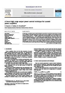
High Precision Linear Motor Control via Relay-Tuning and Iterative Learning Based on Zero-Phase Filtering Kok Kiong Tan, Member, IEEE, Huifang Dou, Yangquan Chen, Student Member, IEEE, and Tong Heng Lee, Member, IEEE
Abstract—In this paper, with a modest amount of modeling effort, a feedback–feedforward control structure is proposed for precision motion control of a permanent magnet linear motor (PMLM) for applications which are inherently repetitive in terms of the motion trajectories. First, a proportional integral derivative (PID) feedback controller is designed using a relay automatic tuning method. An iterative learning controller (ILC) based on zero-phase filtering is applied as feedforward controller to the existing relay-tuned PID feedback controller to enhance the trajectory tracking performance by utilizing the experience gained from the repeated execution of the same operations. Experimental results are presented to demonstrate the practical appeal and effectiveness of the proposed scheme. Index Terms—Convergence analysis, iterative learning control (ILC), linear motor, practical motion control, proportional integral derivative (PID) control, relay tuning, zero-phase filter.
I. INTRODUCTION
P
ERMANENT magnet linear motors (PMLMs) are beginning to find widespread industrial applications, particularly in those requiring a high precision in positioning resolution, such as stages for various key semiconductor fabrication and inspection processes as in step and repeat micro-lithography, wafer dicing, probing and scanning probe microscopy (SPM). The more predominant nonlinear effects underlying a linear motor system are the various friction components (Coulomb, viscous, and stiction) and force ripples (detent and reluctance forces) arising from imperfections in the underlying components [1]. Due to the typical precision positioning requirements and low offset tolerance of their applications, the control of these systems is particularly challenging since conventional proportional integral derivative (PID) control usually may not suffice in these application domains. Some efforts have been made toward more advanced control of PMLM motion systems. In [1], a neural-network (NN)-based feedforward assisted PID controller was proposed. A hybrid control strategy using a variable structure control (VSC) is suggested for submicron positioning conManuscript received March 3, 1999; revised January 10, 2000. Recommended by Associate Editor K. Kozlowski. This work was supported in part by Grant U98-A-032 funded by Gintic Institute of Manufacturing Technology. K. K. Tan, H. Don, and T. H. Lee are with the Department of Electrical Engineering, National University of Singapore, Singapore 119260 (e-mail:
[email protected]). Y. Chen was with the Department of Electrical Engineering, National University of Singapore, Singapore 119260. He is now with Seagate Technology International, Singapore Science Park Design Center, Singapore 118249. Publisher Item Identifier S 1063-6536(01)00516-4.
trol [2]. In these cases and more, the control framework can be described under a feedback–feedforward configuration. In this paper, we are mainly concerned with the applications of the PMLM in operations involving repeated iterations of motion trajectories, such as pick and place assembly operations and many step and repeat process operations. In these typical tasks of PMLM, the time duration for the execution of an operational cycle is short. It is well known that finite-time tracking control is difficult with conventional controllers like the PID controllers which are arguably more suitable for set-point regulation. To achieve a better tracking performance, a feedforward controller is usually applied. In this paper, a new feedforward controller using an ILC algorithm is proposed and developed as a learning enhancement to the PID feedback controller. Under this proposed control structure, two sets of control gains (feedback and feedforward) are to be tuned before the control system may be commissioned. Many PID controller autotuning techniques, based on relay feedback, have been proposed for process control applications [3]. Relay autotuning of PID controllers have also recently been developed for servo systems where an additional time delay has to be introduced into the relay so that a sustained oscillation can be excited [4]. As shown in the experimental studies of [4], an effective set of PID control parameters can be very efficiently and quickly extracted from such an experiment, leading to satisfactory control performance. As for ILC design, although many results on ILC convergence analysis are available, meager results are available on the practical design of an ILC with a modest amount of model knowledge. This paper presents a systematic way of ILC design method using simple zero-phase filtering. In this paper, an -norm on a vector space is defined as , follows: for every
where
is a usual vector norm, e.g.,
We assume contains sampled time function vectors. These functions in continuous time domain are supposed to be , i.e.,
1063–6536/01$10.00 © 2001 IEEE
TAN et al.: HIGH PRECISION LINEAR MOTOR CONTROL
245
is extremely time consuming and cost-inefficient, if not impossible. Therefore, the practical problem is to efficiently control the PMLM with a modest amount of modeling work when only the position measurement is available. This paper contributes to the solution of this practical problem by using a relay autotuned PID controller and an iterative learning controller designed based on simple zero-phase filtering. III. PID FEEDBACK CONTROLLER DESIGN USING ARTIFICIAL RELAY TUNING Fig. 1. Nonlinear block diagram of the linear motor system.
twice continuous and differentiable for all with some exceptions in a finite set . In actual computer controlled systems, is the number of samples most signals belong to where and the dimension of the signal vector.
II. PERMANENT MAGNET LINEAR MOTOR (PMLM)
A. Relay Tuning Clearly, manual tuning of the PID controller’s parameters is tedious and time consuming, and yet unfortunately, the results are often less than satisfactory. An extension of the renowned relay autotuning method to the tuning of our proposed control scheme can be found in [4] as shown in Fig. 2 where is an artificial delay. The modified system transfer function of the position-loop can be approximated by
A. Overall System Description The linear motor considered in the paper is a brushed DC PMLM produced by Anorad Corporation [8].The only measurement available is the translator’s position obtained from an incremental linear optical encoder. Fig. 1 depicts a block diagram model of the motor, showing explicitly the various exogenous and are the time-varying disturbance signals presented. motor terminal voltage and the armature current, respectively; is the motor position; and are the developed and force and the applied load force, respectively. denote the frictional and ripple force, respectively. in, , cludes any uncertainty and disturbance in the system. , and are force constant, back EMF constant, armature resistance, armature inductance and the load of the motor, respectively. B. Friction and Ripple Forces The frictional force affecting the movement of the translator may be modeled as a combination of Coulomb friction, viscous friction, and the component due to Stribeck effect, which can be interpreted as stiction. Apart from friction, one of the known disturbance forces generated in the PMLM is the force ripple due to cogging and reluctance forces presented in the PMLM structure [1]. The force ripple can be described by a sinusoidal function of the load position with a period of pitch distance. In reality, the ripple force is more complex in shape, e.g., due to variations in the magnet dimension.
(1) , , and are the static gain, damping factor, and where may be obnatural frequency, respectively. The static gain tained from a separate velocity step response which will simultaneously yield a good estimate of the time constant, useful for the choice of . It is well known that information on the system frequency reand (the ultimate frequency) sponse between is most useful for control system synthesis. Since is an additional delay cascaded so that identification at phase lag of less than 180 can occur, may be selected according to the empirical guideline of (2) where is a gross estimate of the time constant obtained from the same velocity step response. B. Setting the PID Parameters The remaining parameters in (1) can be obtained by equating the PMLM system and its model at the oscillation frequency , i.e., (3) From (3), the model parameters can be estimated from the following equations:
C. Challenges to Controller Design , and For high precision PMLM motion control, are major challenges to the controller design. Especially, and have nonlinear time varying impact on the system dynamics. The accurate modeling of the whole system
(4)
246
IEEE TRANSACTIONS ON CONTROL SYSTEMS TECHNOLOGY, VOL. 9, NO. 2, MARCH 2001
Fig. 2. Artificial relay feedback arrangement.
A PID controller of the form, is used as the position loop controller. The design objective is such that the closed-loop transfer function is (5) is the desired time-constant of the closed-loop rewhere sponse of the system which is to be specified by the designer. A simple solution for the choice of the parameters of the PID controller is then
tween input and output signals. Using the notation of form, (7) can be written as
-trans-
where and denoting the -transfer function of the FIR filter. Then, the zero-phase (noncausal) filter can be , and can be simply constructed as written as (8)
(6)
IV. FEEDFORWARD CONTROLLER USING ZERO-PHASE–BASED ITERATIVE LEARNING Up to now, a PID feedback controller has been designed with only a relay experiment and a (velocity) step response experiment. Clearly, this feedback controller may not be optimal due to the linear time invariance assumption. However, within a limited frequency range of interest, it is still a reasonable design as shown in the experimental results presented in Section V. The main problem to be addressed is how to improve the control performance using a learning feedforward controller (LFFC). This section presents a solution—iterative learning control, with a detailed design procedure together with a learning convergence analysis. A. Iterative Learning Control The term iterative learning control (ILC) was coined by Arimoto et al. [5] for a better control of repetitive systems. For more information, readers can refer to [7], [6]. It is interesting to note that the noncausal filtering [10], [9], especially zero-phase filtering [11] technique may provide a way for PID-autotuning type design task of ILC. This paper contributes a practical ILC design procedure which has been experimentally verified. B. Zero-Phase FIR Filter and Its Properties In this paper, a class of simple zero-phase filters is considered. , for Given the causal finite impulse response (FIR) filter , the filtered output can be expressed any input signal by
is actuClearly, the above zero-phase FIR filter operator ally a symmetric moving averager. Usually, the coefficients are normalized to one, i.e., (9) of length Lemma IV.1: Given the zero-phase filter with its coefficients normalized as in (9). For any integer , we have (10) Proof: The proof is straightforward using (9) and the sym. metry of coefficients Consider a continuous-time signal . When , it is assumed that sampled at the sampling period of . When applying the above zero-phase on , a contraction mapping can be constructed filter as shown in the following lemma. of length Lemma IV.2: Given the zero-phase filter with its coefficients normalized as in (9). For any , there exists a positive real number , is a which is a function of , such that operator , i.e., contraction mapping on as
(11)
. where For a proof of Lemma IV.2, see [12]. C. Iterative Learning Controller Via zero-phase Filtering
(7) is the length of the FIR filter and “*” denotes the diswhere crete convolution. Therefore, “ ” is a mapping operator be-
A block-diagram is shown in Fig. 4 where FBC stands for “feedback controller” and is the given desired output trajectory to be tracked. After the th iteration (repetitive operation), and the feedback control the feedforward control signal
TAN et al.: HIGH PRECISION LINEAR MOTOR CONTROL
247
where
is bounded by (16)
is a Remark IV.1: It is a common assumption that takes the special random variable with zero mean. When form of (14), in this case, (16) becomes (17)
Fig. 3.
Block diagram of zero-phase filter-based iterative learning control.
signal are to be stored in the memory bank for constructing . the feedforward control signal at the next iteration, i.e., are to be filtered by a The stored feedback control signal multiplied by a learning gain . zero-phase filter The learning updating law is hence given by (12) while the overall control is simply that
. Therefore, in actual applications, is normally where very small. The convergence of the proposed learning controller is in the approaches as increases. This is summarized sense that in the following theorem. Theorem IV.1: A system satisfying assumptions (A1)–(A4) is controlled by a suitable feedback controller as shown in Fig. 3 which performs a given task repeatedly. When applying the zero-phase filtering based ILC scheme (12), there exists a such that the learning process is convergent, i.e.,
where is proportional to and as . A proof of Theorem IV.1 is given in the Appendix. D. Design Procedures
(13) as shown in Fig. 3 where two parameters— , the learning gain and , the length index of the zero-phase filter (8), are to be designed and specified. The simplest form of (12) [11] is (14) is simply an algebraic averager. where In this paper, the detailed form of dynamic system shown as “plant” in Fig. 3 will not be specified. This is not necessary as argued in [14] from the advocated principle of self support (PSS) because the stored control signals are in essence the plant itself. Therefore, instead of making some assumptions on the system class to be controlled, we can equivalently preassume some properties on the control signals which may be more direct and practical. For practical systems, it is reasonable to assume the following. (A1) The plant to be controlled is stabilizable and further, internally stable. (A2) The number of inputs is equal to the number of outputs (measurement variable). exists uniquely for a (A3) The desired control input . given desired output trajectory can be decomposed into a (A4) The system dynamics and a nonrepeatable part , repeatable part i.e., (15)
One frequently used zero-phase filter, an algebraic averager, is considered as an example for illustrating the design consideration. Its frequency response can be computed as (18) is very important. 1) Design of : A suitably chosen will bring in more high-frequency signal components Small stored in the memory bank. This is the key reason of the divergence for some ILC schemes which may be convergent at the initial iterations but as ILC runs, divergence can be observed in practical applications [9]. Meanwhile, an unnecessarily large deteriorates the signal’s low-frequency components while smoothing out the high-frequency components. A practical design procedure is proposed as follows. At the first iteration only the feedback controller is commissioned. At the end of the first iteration, performing a discrete Fourier transgives the spectrum of form (DFT) of the feedback signal of the the feedback signal. Therefore, the cutoff frequency should be chosen a little bit higher filter can be obtained. than the frequency corresponding to the magnitude peak in the . Using and setting amplitude-frequency plot of (19) will give an estimate of , given in (18)
for a given
. For example, for
248
IEEE TRANSACTIONS ON CONTROL SYSTEMS TECHNOLOGY, VOL. 9, NO. 2, MARCH 2001
Iterating (26)
and one gets (20) using bolic Math Toolbox. Therefore
(27)
of MATLAB SymClearly, the convergence condition is that (21)
Remark IV.2: According to Shannon’s sampling theorem, should be larger than two. Thereapproximately, should not be less fore, in any case, it can be concluded that and is finite, the than two. This implies that when ILC scheme (22) which was analyzed in [13], may not actually work well in practice. 2) Design of : A suitably designed depends on what kind of knowledge is assumed about the plant to be controlled. In practice, one can always start with a smaller, conservative via which the learning process converges. Then fine tuning of is still possible depending on what plant knowledge is available. In most engineering practice, it is quite common that the frequency response of the system is partially available. Since the system considered is controlled by a feedback controller, the is assumed to be availclosed-loop transfer function able. In this section, a linear system model is used because at certain range of frequencies concerned, from the Bode plot, it is always possible to approximate the practical system by a linear system. may be sometimes Full knowledge of impractical. Therefore, it is assumed that at least the value of is available. In what follows, it will be shown that can be used to design a reasonable . and as the transfer functions of the Denote feed ack controller and the open-loop plant, respectively. Then (23) Writing the ILC updating law (12) in the frequency domain gives (24) denotes the frequency domain counterpart of where is omitted for brevity. Since the following, be written by
. In can
(28) The converged value is given by (29) . which requires an inverse of Condition (28) may not be applicable for all . Therefore, is considered. only less than a frequency of interest, say, Designing is then to solve (30) is known as shown, for example, in (18), can be Since . A plot of is availobtained from the knowledge of able from (30). This plot is useful in selecting a suitable when different frequencies of interest are to be considered. Usually, , one can still determine a with the only information of suitable . V. EXPERIMENTAL STUDIES A. Testbed System In the experimental studies, an Anorad laboratory testbed system is used. The control algorithms are implemented on an MX-31 DSP development system from Integrated Motions, Inc. (IMI), which utilizes a Texas Instruments TMS320c31 32-bit floating point processor with 60 ns single-cycle instruction execution time. Control programs are written in C, compiled on an IBM personal computer (PC) which can be downloaded into the MX-31 through a serial communication link. The position encoder is the only transducer available and the measurements can be transmitted to the PC through the same serial communication link. In our experiments, the encoder resolution is 1 m. All data stored in MX-31 can be uploaded to the PC for post-analysis in a Matlab environment. B. Control Task The particular PMLM considered in this work is a brushed DC PMLM LS-B series LS1-24 manufactured by Anorad Corporation [8]. The maximum effective travel length is 609.6 mm and the maximum velocity is 0.5 m/s. A typical point-point desired tracking trajectory is specified as (31)
(25) is the frequency domain transformation of where becomes
, (24)
(26)
(32) . Note that the velocity where is normally set to zero. profile is in a bell form and The control task is to track the given desired trajectories (31) and (32) as close as possible in a finite fixed time duration as the operation repeats from cycle to cycle.
TAN et al.: HIGH PRECISION LINEAR MOTOR CONTROL
Fig. 4.
249
Position tracking errors with PID feedback control.
C. Design of PID Feedback Controller PID controller can be easily designed via two experiments: 1) velocity step response and 2) a relay autotuning under the guidelines given in Section III. Two experiments have been carried out for comparing the PID control performance with PMLM running at the minimum and maximum velocities. As shown in Fig. 4, the feedback PID control thus tuned exhibit satisfactory tracking performance as well as robustness. D. Iterative Learning Feedforward Controller Design We will now apply the systematic method developed in Section IV-D to the design of the ILC. For illustration purposes, we shall present some experimental results for several different combinations of and . To obtain a guideline for the ILC parameter design, we follow the considerations in Section V-C where the closed-loop system to 0.008 s. Applying (21), bandwidth is 20 Hz when setting one obtains
while using
When increases, the upper bound for will also increase. , the upper bound for becomes For example, when 2.8289 instead of two. For an effective implementation of the ILC, the following additional issues should be considered. • Initialization. As one of the postulates [5] in ILC formulation, the system is required to be reset at the identical initial state after each repetition of the motion trajectory, since the error in initialization will affect the final tracking performance directly and adversely. This is especially so for the PMLM system, where the ripple force varies with the position of the translator. The proposed control scheme is able to achieve an accurate initialization automatically. This is possible because the set-point tracking accuracy can be achieved within 0.02% by the relay-tuned PID controller alone and the same PID controller may be used for the set-point regulation after completion of each repetition to reset the initial conditions to the same state. It is critical to correct the value of set-point during the initialization via PID control. The terminal tracking error of the last repetition can be used for this correction. • Signal Filtering. The position measurement used is an averaged value of three consecutive A/D samples. An averaging finite difference formula is also used for velocity estimation, i.e., (33)
gives
where a practical choice of is three. It has been validated in many robotic applications that the simple scheme (33) is equivalent to many advanced and complex schemes.
250
IEEE TRANSACTIONS ON CONTROL SYSTEMS TECHNOLOGY, VOL. 9, NO. 2, MARCH 2001
= 0:1 with different M .
Fig. 5.
Learning convergence comparison, fixed
Fig. 6.
Learning convergence comparison, fixed M = 10 with different .
E. Experimental Results on PID Plus ILC Control Scheme When the relay tuned PID controller is applied alone, the results were presented in Section V-C. It can be shown that a fixed PID controller tuned by artificial relay feedback experiment performs well for minimal velocity and maximal velocity situations. In what follows, it will be illustrated that, using a
simple ILC scheme (14), the tracking performance can be improved significantly. The feedback PID controller is the same as the one used in Section V-C. 1) Fixed with Different : A cautious is chosen to be 0.1. Different filter lengths were used to test the ILC conver, it is not convergent gence. As shown in Fig. 5, when for the reasons in Remark IV.2. However, the ILC convergence
TAN et al.: HIGH PRECISION LINEAR MOTOR CONTROL
251
= 10 = 0:1.
Fig. 7.
Feedforward control signals during iterative learning process, fixed M
Fig. 8.
Feedback control signals during iterative learning process, fixed M = 10 = 0:1.
at several initial iterations can be observed. The similar situation . When , the ILC exhibits happened when good convergence property. When increases to 20, no further significant improvement can be obtained. This verifies the ILC design formula (21). 2) Fixed with Different : As verified in Fig. 5, a suitable ( ) is chosen and fixed. Contrary to Section V-E-1, different learning gains were used here to test the ILC conver-
gence. As shown in Fig. 6, when increases, ILC converges faster. However, sustainable ILC convergence (or long-term stability of ILC [9]) will not be guaranteed as increases from 0.3 and beyond. To have a clear understanding about the proposed ILC scheme, a series of plots for feedforward and feedback control signals at several ILC iterations are shown in Figs. 7 and 8. We can see that the feedforward control signal converges from zero to the repeat-
252
IEEE TRANSACTIONS ON CONTROL SYSTEMS TECHNOLOGY, VOL. 9, NO. 2, MARCH 2001
able part of the feedback control signal (see Fig. 7). On the other hand, the feedback control signal, as shown in Fig. 8, reduces as ILC converges. It is true that the feedback control signal at the 50th iteration is almost a zero mean random signal. This verifies the assumption (A4) in Section IV-C. Collectively from Figs. 7 tends and 8, it can be observed that through iterative learning to relieve the burden of feedback controller. This implies, critical or optimal design of a feedback controller may not be necessary.
and when therefore, (37) becomes (41) When
tends to zero (42)
VI. CONCLUSION It has been successfully shown in this paper that, with a modest amount of modeling, it is possible to achieve precision motion control of a PMLM. A feedback–feedforward control structure is proposed for applications which are inherently repetitive in terms of the motion trajectories. A relay-tuned PID feedback controller is used together with an iterative learning feedforward controller. An additional delay is introduced to achieve self-induced controlled oscillations from which the PID controller can be automatically tuned. By using a simple zero-phase filtering technique, the design task of ILC is reduced to tuning two parameters: length of the filter and the learning gain. Convergence analysis and detailed design procedures are presented. Some practical considerations in the parameter tuning are outlined. Experimental results are presented to demonstrate the practical appeal and effectiveness of the proposed scheme. The clearly illustrated controller design procedures are also appealing for other applications. APPENDIX PROOF OF THEOREM IV.1 Proof: From (13), the feedback signal at the th iteration can be written as
(34) Applying the filtering operator
on both sides of (34) gives (35)
Substituting (35) into the learning updating law (12), one obtains (36) Iterating in (36)
(37) It is shown in Lemma IV.2 that the operator contraction mapping, i.e.,
(40)
is a (38)
While (39)
ACKNOWLEDGMENT The authors are grateful to the anonymous reviewers and in particular, Associate Editor, Prof. K. Kozlowski, for their helpful comments. REFERENCES [1] G. Otten, T. J. A. de Vries, J. van Amerongen, A. M. Rankers, and E. W. Gaal, “Linear motor motion control using a learning feedforward controller,” IEEE/ASME Trans. Mechatron., vol. 2, pp. 161–170, 1997. [2] S. Chang, S. H. Wu, and Y. Hu, “Submicrometer overshoot control of rapid and precise positioning,” J. Amer. Soc. Precision Eng., vol. 20, pp. 161–170, 1997. [3] K. J. Astrom and T. Hagglund, “Automatic tuning of simple regulators with specifications on phase and amplitude margins,” Automatica, vol. 20, no. 5, pp. 645–651, 1984. [4] K. K. Tan and T. H. Lee, “Automatic tuning of PID cascade controllers for servo positioning systems,” Int. J. Intell. Automat. Soft Comput., vol. 4, no. 4, pp. 325–339, 1998. [5] S. Arimoto, S. Kawamura, and F. Miyazaki, “Bettering operation of robots by learning,” J. Robot. Syst., vol. 1, no. 2, pp. 123–140, 1984. [6] K. L. Moore, “Iterative learning control—An expository overview,” Appl. Comput. Contr., Signal Processing, Circuits, 1998. [7] J. Xu and Z. Bien, “Frontiers in iterative learning control,” in Iterative Learning Control—Analysis, Design, Integration and Applications, Z. Bien and J.-X. Xu, Eds. Boston, MA: Kluwer, 1998. [8] Anorad, Inc., “Linear servo motors—Anoline Series,”, 1997. [9] R. W. Longman, “Designing iterative learning and repetitive controllers,” in Iterative Learning Control—Analysis, Design, Integration and Application, Z. Bien and J.-X. Xu, Eds. Boston, MA: Kluwer, 1998, pp. 107–145. [10] J. Craig, “Adaptive control of manipulators through repeated trials,” in Proc. Amer. Contr. Conf., San Diego, CA, June 1984, pp. 1566–1573. [11] E. Burdet, L. Rey, and A. Codourey, “A trivial method of learning control,” in Proc. 5th IFAC Symp. Robot Contr., vol. 2, Nantes, France, 1997, IFAC. [12] Y. Chen, T. H. Lee, J.-X. Xu, and S. Yamamoto, “Noncausal filtering based design of iterative learning control,” in Proc. 1st Int. Workshop Iterative Learning Contr., K. L. Moore, Ed., Tampa, FL, Dec 1998, pp. 63–70. [13] T.-Y. Kuc, J. S. Lee, and K. Nam, “An iterative learning control theory for a class of nonlinear dynamic systems,” Automatica, vol. 28, no. 6, pp. 1215–1221, 1992. [14] Z. Novakovic, “The principle of self-support in control systems,” in Studies in Automation and Control. Amsterdam, The Netherlands: Elsevier, 1992, vol. 8.
Kok Kiong Tan (S’94–M’99) received the B.Eng. degree in electrical engineering with honors and the Ph.D. degree from the National University of Singapore (NUS) in 1992 and 1995, respectively. He was a Research Fellow of Gintic, a national R&D institute spearheading the promotion of R&D in local manufacturing industries, from 1995 to 1996. During his stay there, he was involved in several industrial projects with various companies, including MC Packaging Pte Ltd., Panalpina World Transport, and SATS cargo. He then joined NUS as a Lecturer. His current research interests are in the applications of advanced control techniques to industrial control systems and mechatronic systems.
TAN et al.: HIGH PRECISION LINEAR MOTOR CONTROL
Huifang Dou received the B.Eng. degree in industrial automation from Wuhan University of Technology, Wuhan, China, and the M.Eng. degree in automatic control from Beijing Institute of Technology, Beijing, China, in 1985 and 1988, respectively. She received the Ph.D. degree from the Department of Precision Instrument and Mechanology, Tsinghua University, Beijing, China, in April 1997. She served as a Lecturer with the Department of Precision Mechanical Engineering, Xi’an Institute of Technology, Xi’an. She has been working as a Research Fellow with the Department of Electrical Engineering, National University of Singapore. Her current research interests include servomechanism, precision motion control, embedded systems, and real-time computing.
Yangquan Chen (S’95–S’98) received the B.Eng. degree in industrial automation from University of Science and Technology of Beijing, Beijing, China, and the M.Eng. degree in automatic control from Beijing Institute of Technology (BIT) in 1985 and 1989, respectively. He received the Ph.D. degree from the School of Electrical and Electronic Engineering, Nanyang Technological University (NTU), Singapore, in July 1998. He visited the Space Research Corporation (SRC, Belgium) and was invited to BIT, as a Guest Researcher for flying vehicle projects. From 1987 to 1995, he had been with the Department of Electrical Engineering of Xi’an Institute of Technology (XIT). He had served as a Department Head since 1992 and an Associate Professor since 1994. He received a number of ministerial level awards for his excellence in teaching and academic research in China. Since January 1996, he joined the Department of Electrical Engineering, National University of Singapore (NUS) as a Research Engineer and then a Professional Officer. Since March 1999, he has been working with Seagate Technology International, Singapore Science Park as a Senior R&D Engineer for hard disk drive servo control where his work has led to a number of pending U.S. patents. he has authored more than 80 technical papers. His current research interests include servomechanism, iterative/repetitive/adaptive learning control, curve identification, robot control, batch process control, static/dynamic optimization, and optimal control problem solver.
253
Tong Heng Lee (M’88) received the B.A. degree with First Class Honors in the engineering tripos from Cambridge University, Cambridge, U.K., and the Ph.D. degree from Yale University, New Haven, CT, in 1980 and 1987, respectively. He is a Professor in the Department of Electrical Engineering at the National University of Singapore. He is also currently Head of the Control Engineering Division in this Department, and the Vice-Dean (Research) in the Faculty of Engineering. His research interests include adaptive systems, knowledge-based control, and intelligent mechatronics. He has published extensively in these areas, and currently holds Associate Editor appointments in Automatica, Control Engineering Practice, the International Journal of Systems Science, and Mechatronics. Dr. Lee was a recipient of the Cambridge University Charles Baker Prize in Engineering. He is an Associate Editor of the IEEE TRANSACTIONS ON SYSTEMS, MAN, AND CYBERNETICS.