226
IEEE Transactions on Ultrasonics, Ferroelectrics, and Frequency Control ,
vol. 58, no. 1,
January
2011
Correspondence High-Spatial-Resolution SubSurface Imaging Using a Laser-Based Acoustic Microscopy Technique Oluwaseyi Balogun, Garrett D. Cole, Robert Huber, Diane Chinn, Todd W. Murray, and James B. Spicer Abstract—Scanning acoustic microscopy techniques operating at frequencies in the gigahertz range are suitable for the elastic characterization and interior imaging of solid media with micrometer-scale spatial resolution. Acoustic wave propagation at these frequencies is strongly limited by energy losses, particularly from attenuation in the coupling media used to transmit ultrasound to a specimen, leading to a decrease in the depth in a specimen that can be interrogated. In this work, a laser-based acoustic microscopy technique is presented that uses a pulsed laser source for the generation of broadband acoustic waves and an optical interferometer for detection. The use of a 900-ps microchip pulsed laser facilitates the generation of acoustic waves with frequencies extending up to 1 GHz which allows for the resolution of micrometer-scale features in a specimen. Furthermore, the combination of optical generation and detection approaches eliminates the use of an ultrasonic coupling medium, and allows for elastic characterization and interior imaging at penetration depths on the order of several hundred micrometers. Experimental results illustrating the use of the laser-based acoustic microscopy technique for imaging micrometer-scale subsurface geometrical features in a 70-μm-thick single-crystal silicon wafer with a (100) orientation are presented.
I. Introduction
S
canning acoustic microscopy (SAM) techniques have been widely used for the elastic characterization and interior imaging of solid structures [1], [2]. In these techniques, ultrasound is focused on a small spot in a specimen, and the amplitude and propagation time of the ultrasound are monitored to map the spatial variation in the mechanical and geometric properties of the specimen. The spatial resolution of SAM techniques increases with the ultrasonic frequency, and micrometer-scale spatial
Manuscript received June 6, 2007; accepted September 29, 2010. This work was performed under the auspices of the U.S. Department of Energy by the University of California, Lawrence Livermore National Laboratory under Contract No. W-7405-Eng-48 and was based on work supported by, or in part by, the U.S. Department of Energy, Office of Basic Energy Sciences under grant number DEFG0203ER46090. One of the authors, T. W. Murray, acknowledges the support provided for this work by the National Science Foundation under grant number CMS-0448796. O. Balogun is with the Mechanical Engineering Department, Northwestern University, Evanston, IL (
[email protected]). G. D. Cole, R. Huber, and D. Chinn are with the University of California, Lawrence Livermore National Laboratory, Livermore, CA. T. W. Murray is with the Mechanical Engineering Department, University of Colorado at Boulder, Boulder, CO. J. B. Spicer is with the Materials Science and Engineering Department, The Johns Hopkins University, Baltimore, MD. Digital Object Identifier 10.1109/TUFFC.2011.1789 0885–3010/$25.00
resolution is achievable at gigahertz frequencies. However, because of strong ultrasonic attenuation in the gigahertz range stemming from damping through the coupling media used to transmit ultrasound into the specimen, SAM techniques operating in this frequency range are used primarily for near-surface materials characterization [1]. Laser-based ultrasonics (LBU) techniques provide an attractive alternative to SAM techniques for the generation and detection of ultrasound, and have been used in a variety of materials characterization applications [3]– [9]. In these techniques, a pulsed excitation laser is typically used for ultrasound generation. The pulsed laser is delivered to a specimen surface, where the laser energy is absorbed, leading to localized specimen heating. Local thermal stresses are produced following the specimen heating, which relax by launching ultrasound in the specimen by transient thermoelastic expansion. The generated ultrasound is detected at the specimen surface by monitoring the surface displacement or strain using an optical interferometer or a diffraction-based probe. LBU techniques allow for the generation and detection of ultrasound without the use of ultrasonic coupling media, allowing for potential improvements in the ultrasonic penetration depth for imaging elastic and geometrical properties in materials. The non-contact aspect of LBU techniques is also attractive when working with materials that can be contaminated by the coupling medium used in SAM techniques. The generation and detection laser spot sizes on a specimen surface can be controlled using focusing lenses, allowing for materials characterization with high lateral spatial resolution. Furthermore, LBU techniques allow for nondestructive inspection of material properties. The majority of the LBU techniques reported in the literature can be classified under two broad ultrasonic frequency regimes. In the low-frequency regime, Q-switched pulsed laser sources with pulse durations in the range of 7 to 100 ns are used for ultrasound generation [10], [11]. The bandwidth of the generated ultrasound in this regime is in the kilohertz to tens of megahertz range, which is suitable for a variety of nondestructive testing and medical imaging applications for which the spatial resolution requirements are typically on the order of 1 mm. In the second regime, ultrafast laser sources with pulse widths in the range of 80 to 130 fs are used for the generation of broadband longitudinal waves with frequencies extending up to several hundred gigahertz [12]–[18]. At these frequencies, the ultrasonic wavelengths in solids are in the tens to hundreds of nanometers range, which is suitable for the elastic characterization of nanoscale structures. The bandwidth of the longitudinal waves also allows for time-resolved acoustic microscopy on a picosecond time scale. Strong attenuation of ultrafast laser-generated ultrasound in solids at room temperature limits the specimen penetration depth in this frequency regime to the nanoscale [17], [18].
© 2011 IEEE
balogun et al.: high-spatial-resolution sub-surface imaging
227
Fig. 1. Schematic of the laser acoustic microscopy system. NA = numerical aperture, PZT = piezoelectric actuator.
It is desirable to develop LBU techniques for resolving micrometer-scale elastic and geometric variations in structural materials, where the feature depth of interest is in the range of tens to several hundred micrometers. One such application is the elastic characterization and internal imaging of the National Ignition Facility (NIF) target materials that are currently under development at the Lawrence Livermore National Laboratory. The NIF target materials have micrometer-scale internal features and are several hundred micrometers in thickness. These materials also have limited tolerance for sample contamination, which makes LBU techniques an attractive characterization method. To inspect these structures, the measurement approach adopted involves tailoring the wavelength of the generated ultrasound to the micrometer range; in most solids, the corresponding ultrasonic frequency is in the mid-frequency regime between 500 MHz and 4 GHz. The limiting effect of material dependent ultrasonic attenuation in this frequency range is not as severe as in the hundreds of gigahertz range, thus allowing for longer specimen penetration depths to be inspected. Although laser generation of ultrasound in the mid-frequency regime has been addressed by various authors using point or line focused laser sources with pulse durations in the hundreds of picoseconds to femtosecond range, these works have mostly focused on near-surface materials characterization and imaging using surface acoustic waves [19]–[27]. To interrogate depths comparable to the thickness of the NIF targets while working in the mid-frequency range, the use of bulk longitudinal and shear waves may be more advan-
tageous than surface waves. In this work, a laser acoustic microscopy system is presented that uses a 900-ps microchip pulsed laser for the generation of broadband bulk waves with frequency components reaching 1 GHz. Experimental results that show the potential of the system for imaging micrometer-scale subsurface geometrical features in a 70-μm thick single crystal silicon wafer with a (100) orientation are presented. The interior lateral spatial resolution of the laser acoustic microscopy system is estimated from a scan across an abrupt sub-surface edge. II. Experiment A. Experimental Setup A schematic of the laser acoustic microscopy system is shown in Fig. 1. A neodymium-doped yttrium aluminum garnet (Nd:YAG) microchip laser is used for ultrasonic wave generation. The laser has a pulse energy of 5 μJ, a pulse width of 900 ps, a repetition rate of 50 kHz, and a wavelength of 1064 nm. The generation laser is collimated and delivered to a gimbal scanning mirror. The reflected beam from the gimbal mirror passes through a set of relay lenses and a dichroic mirror, and is then focused by a 20× long-working-distance microscope objective on the sample surface to a minimum circular spot of diameter D ≈ 3 μm at the full-width at half-maximum (FWHM) intensity level. The separation distances between the gimbal mirror, the relay lenses, and the microscope objective are
228
IEEE Transactions on Ultrasonics, Ferroelectrics, and Frequency Control ,
Fig. 2. Geometry of the micro-fabricated silicon sample.
chosen such that these optics are configured as a 4f optical imaging system. The 4f imaging system is used to scan the generation laser spot on the sample surface by changing the entry angle of the laser into the microscope objective. The normal sample surface displacement associated with the interaction of the generated ultrasound with the sample boundary is detected using a path-stabilized Michelson interferometer. The interferometer uses a frequency-doubled Nd:YAG laser with a wavelength of 532 nm. The detection laser is delivered into the experimental setup through a single mode optical fiber, collimated, and directed to a beam splitter that splits the light into signal and reference beams. The signal beam is directed to the sample surface through the microscope objective and is redirected on reflection from the sample surface to a high-speed photodetector with a rise time of 1 ns. The circular diameter of the signal beam on the sample surface is 1.2 μm at the FWHM. The reference beam is delivered to a reference mirror that redirects the beam to the photodetector where it interferes with the signal beam producing an intensity-modulated signal that is related to the absolute displacement of the sample surface. The interferometer is stabilized at the point of maximum displacement sensitivity through active adjustment to the optical path length difference between the reference and signal beams. This is achieved by electronically dithering the reference mirror using a piezoelectric actuator. The output signal from the photodetector is recorded using a digital oscilloscope at the rate of 10 GS/s and sent to a computer for data processing. The oscilloscope is triggered for data acquisition by an input signal from a photodetector that samples a portion of the generation laser before it is delivered to the sample surface for ultrasound generation. The sample is supported on a three-axis translation stage and a computer-based interface program is used to control the stage. B. Sample Fabrication The test sample used consists of a 70-μm-thick (100) single-crystal silicon wafer with one face etched using standard photolithography techniques to produce a patterned surface. A schematic of the sample is shown in Fig. 2. Because of the long optical absorption depth of the generation laser in silicon, a 207-nm thick aluminum film was deposited on the unpatterned surface of the wafer. The
vol. 58, no. 1,
January
2011
optical skin depth for the generation laser in aluminum films is less than 20 nm, allowing for enhanced generation of broad bandwidth ultrasound in the silicon sample. The photomask used to generate the etched topography was originally designed for the fabrication of micromechanically-tunable vertical-cavity semiconductor optical amplifiers [28] and was chosen for its appropriate dimensions as well as the variety of geometries present, including orthogonal and curved features. The silicon wafer was initially cleaved to obtain small chips with lateral dimensions of 1 cm by 1 cm. The cleaved chips were patterned using a deep reactive ion etch system with a standard cyclic process (SF6 as the etchant, alternating with C4F8 for passivation) and protected with a photoresist mask. To improve thermal transfer during etching, the silicon chips were mounted on a carrier wafer using a thin layer of resist. The exposed silicon surface was etched for 2.5 min, resulting in a feature height of approximately 3.5 µm. Following the silicon etch, the chips were removed from the carrier wafer and the masking resist was stripped using a combination of organic solvents and oxygen plasma ashing. After a thorough cleaning, an aluminum film was deposited on the unpatterned surface by electron beam evaporation. C. Measurement and Signal Analysis Approach The generation and detection lasers were aligned on the unpatterned sample surface coated with the aluminum film. The spot size of the generation laser on the sample surface was expanded to a diameter of about 30 μm by adjusting the position of the relay lenses and defocusing the light. Expansion of the generation laser beam diameter was necessary to avoid ablating the sample while maintaining high total laser energy deposited in the sample. The specimen was also inspected under an optical microscope after the experiment and no visible evidence of sample ablation was observed. Fig. 3(a) shows a time trace of the normal displacement measured at a point on the sample surface as the laser-generated ultrasound propagates through the sample. The waveform was averaged 700 times to minimize the incoherent noise in the data. The waveform shows a rapid thermal expansion caused by sample heating from the absorbed laser pulse energy, followed by a slowly decaying tail. Several transient arrivals corresponding to acoustic wave reflections from the bottom surface of the sample and low-frequency ringing are also present. Identifying the acoustic wave transients can be challenging for two reasons. First, the acoustic wave amplitudes are small; second, the wave propagation direction corresponds to the 〈100〉 direction, which supports several acoustic modes including the pure longitudinal, pure shear, and mode-converted shear/longitudinal waves that arrive close to each other. The longitudinal and shear waves are polarized in the normal and in-plane directions. The configuration of the experimental setup facilitates measurement of the normal surface displacement associated with the interaction of the longitudinal wave with the sample surface. A fraction of the in-plane shear wave dis-
balogun et al.: high-spatial-resolution sub-surface imaging
placement may also be measured in the normal direction because of the Poisson’s effect. To identify these acoustic wave reflections, the thermal expansion signal seen in Fig. 3(a) was removed by fitting an exponential decay curve to the data and subtracting the thermal expansion signal. A portion of the resulting waveform obtained is shown in Fig. 3(b). The longitudinal wave reflections labeled as P2, P4, and P6 in the figure are clearly identified in the waveform. The pulse width of the longitudinal wave echoes is seen to decrease with propagation distance because of geometric acoustic spreading, leading to a shift in the center frequency of the amplitude spectrum of the waves to higher frequencies as it travels through the specimen. This trend has also been observed by Daly et. al. [29] in single-crystal silicon specimens along the 〈100〉 propagation direction using acoustic phonons in the hundreds of gigahertz range. Note that the pulse width of the P6 reflection is approximately 1.0 ns and the frequency content extends to 1 GHz. The time difference Δt between successive peaks or troughs of the longitudinal wave reflections is 14.8 ns, which corresponds to the round trip time of the longitudinal wave in the sample. Δt is related to the longitudinal wave velocity c1, and the sample thickness h, by Δt = 2h/c1. Taking cl = 8.44 μm/ns along the 〈100〉 direction in silicon [2], the sample thickness is estimated to be 62.4 μm. This measured value is close to the nominal value of 70 μm quoted by the manufacturer and is verified by wafer thickness measurements using a pneumatic thickness probe to be 62.0 μm. It is also important to point out that the P6 reflection traversed a total distance of 375 μm in the sample; its amplitude is smaller than the P2 reflection because of geometric attenuation stemming from the pulse-echo configuration of the measurement system. Nevertheless, the amplitude of the P6 reflection is clearly visible above the noise, suggesting that the excited longitudinal wave can penetrate through a silicon sample having a thickness of half the propagation distance of the P6 reflection while maintaining the gigahertz ultrasound bandwidth. The material related ultrasonic attenuation in silicon is negligibly small at 1 GHz (≈1 db/mm along the 〈100〉 direction [2]), and the limiting penetration depth would depend on the extent of geometric attenuation and the measurement signal-to-noise ratio. The ultrasonic resonant modes excited by the laser source in the specimen are identified by taking the Fourier transform of the processed waveform [Fig. 3(b)]. The amplitude spectrum is shown in Fig. 3(c). The amplitude peaks in the data occur at frequencies corresponding to the zero group velocity (ZGV) resonance modes. These modes occur at the minimum frequency of the higherorder antisymmetric and symmetric Lamb wave modes where the group velocity goes to zero while the phase velocity remains finite. For instance, the largest amplitude peak in Fig. 3(c) occurs at 65.6 MHz and corresponds to the S1 ZGV resonance that occurs at the turning point of the first symmetric (S1) Lamb wave mode. Details concerning laser generation of ZGV modes can be found in the literature [30]–[33].
229
Fig. 3. Time-domain waveform obtained in the silicon sample with the source and receiver on epicenter: (a) measured signal and (b) processed waveform without the thermal expansion signal for the time window 10 to 70 ns. (c) Amplitude spectrum of the waveform in (b).
IEEE Transactions on Ultrasonics, Ferroelectrics, and Frequency Control ,
230
vol. 58, no. 1,
January
2011
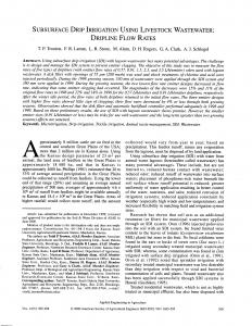
To map the etched pattern at the bottom of the silicon sample, the sample was scanned with the translation stage in a two-dimensional area relative to the collocated excitation and detection laser spots on the sample surface. At each measurement point, a time domain waveform was recorded and the arrival times of the amplitude peak of the P2 reflection in the measured waveform and the ZGV resonance peak close to 410 MHz in the amplitude spectrum of the measured waveform were monitored. Note that in Fig. 3(b), the amplitude peak of the P2 reflection occurs at 16.4 ns relative to time zero set by the trigger signal. The 410-MHz resonance peak was chosen over other higher-frequency peaks in the amplitude spectrum because it provided a sharper image contrast and higher signal-to-noise ratio. III. Results and Discussion A. Sub-Surface Imaging Fig. 4(a) shows the c-scan image of the arrival time of the peak amplitude of the P2 reflection measured over a 400 μm by 400 μm area. In this experiment, the sample was raster scanned in 5-μm steps, and the waveform obtained at each measurement point was analyzed as explained in Section II-C. At each point, 700 waveforms were acquired and averaged to minimize the measured background noise. The measurement time per point is approximately 1 s. The change in arrival time of the P2 reflection seen in the c-scan reveals the etched pattern at the bottom of the sample. A scanning electron microscopy (SEM) image of the pattern taken from the etched side of the sample is shown in Fig. 4(b). The etched pattern in the c-scan and the SEM image are in good agreement. The slight tilt in the etched pattern seen in the c-scan image when compared with the SEM image results from the fact that the sample was not aligned with respect to a common datum when both images were taken. The maximum change in arrival time of the P2 reflection observed in the c-scan image is about 0.8 ns, equivalent to a thickness change of 3.4 μm and is close to the expected value of 3.5 μm obtained from a scanning white-light interferometer. The c-scan image of the longitudinal thickness resonance frequency measured over the same area shown in Fig. 4(c) reveals the subsurface pattern as well. A maximum frequency shift (Δf) of 24 MHz is represented in the image, which corresponds to a sample thickness variation of Δh = (Δf/f)h, where h = 62.4 μm is the thickness of the un-etched silicon sample. Using the expression for Δh, the height of the etched pattern obtained from the resonance c-scan image is 3.7 μm, which is slightly greater than the value obtained from the time-of-flight c-scan image. Compared with the c-scan image obtained using the time-of-flight of the P2 reflection, the c-scan image of the ZGV resonance does not show a noticeable edge effect. The ability to resolve the sub-surface pattern demonstrates the high sensitivity of the laser acoustic microscopy system for internal imaging in solids.
Fig. 4. Images of the sub-surface pattern etched into the silicon sample: (a) time-of-flight c-scan of the P2 reflection, (b) scanning electron microscopy image of the etched pattern, and (c) c-scan image of the ZGV resonance frequency close to 410 MHz.
balogun et al.: high-spatial-resolution sub-surface imaging
231
Furthermore, these measurements can be conducted using either a broadband approach in which transient longitudinal modes are generated and detected or a narrowband approach based on the ZGV resonances. B. Spatial Resolution To determine the lateral spatial resolution of the system at the feature depth, a line scan with a step size of 1 μm was taken across an edge of one of the etched features in the sub-surface pattern. Fig. 5 shows the measured edge response obtained by recording the arrival time of the peak amplitude of the P2 reflection. To determine the position of the P2 amplitude peak with high temporal resolution, the sampling period of the time domain data was decreased from 100 ps/point to 1 ps/point through zero padding in the frequency domain [34]. Note that neither the magnitude nor the phase spectrum of the waveform is altered by this operation; the bandwidth, amplitude, and arrival time of the transient arrivals in the reconstructed time domain data are the same as in the original waveform. The maximum variation in the measured time-offlight estimated from the interpolated time data between 130 μm and 170 μm in Fig. 5 is about 1.1% of the mean value of 17.44 ns. The sharp transition region observed in Fig. 5(a) requires further explanation. As the source and receiver are scanned over the step, P2 reflections are observed from both the upper (labeled t1) and lower (labeled t2) surfaces of the step as shown in Fig. 5(b). In the transition region, the dominant peak shifts abruptly from t1 to t2 as the source and receiver pass over the center of the step. The transition region in the time-of-arrival data does not give a measure of the lateral resolution, or the ability to resolve closely spaced objects, of the system. It simply shows that as the source and receiver approach the step the amplitude of arrival t1 is greater than t2, and while just over the center of the step, the amplitude of t2 is greater than t1. An exception to this general trend occurs at two points in Fig. 5(a) close to 180 μm where an abrupt jump in the arrival time is observed. This occurs because the P2 reflection from the lower surface of the step is stronger than the reflection from the upper surface of the step. To get a true measure of the lateral resolution of the system, the amplitude of the arrival at time t1 is measured as the source and receiver are scanned over the step. The result is shown in Fig. 5(c). The dotted line shows that the data can be well approximated by an integrated Gaussian function. Assuming that the physical shape of the edge can be approximated by a step function, the lateral spatial resolution of the laser acoustic microscopy system can be estimated based on the width of the line spread function. The line-spread function, obtained from the deconvolution of the integrated Gaussian fit to the amplitude data and a step function, is shown in Fig. 6. The lateral spatial resolution estimated based on the FWHM of the curve is 37 μm. Note that the lateral resolution is controlled in pulse-echo experiments by the thickness of the sample
Fig. 5. Edge response of the laser acoustic microscopy system: (a) spatial variation in the arrival time of the P2 reflection, (b) a portion of the waveform obtained at measurement positions that are close and far away from the step; t1 and t2 correspond to the arrival times of the P2 reflection from the top and bottom of the edge, (c) peak amplitude of the P2 reflection at t1 as a function of lateral distance.
232
IEEE Transactions on Ultrasonics, Ferroelectrics, and Frequency Control ,
vol. 58, no. 1,
January
2011
structures where microscale spatial resolution is required over depths reaching hundreds of micrometers. Acknowledgments The authors acknowledge Dr. C. Prada at the Laboratoire Ondes et Acoustique, Paris, for helpful discussions on the ZGV resonance modes. References
Fig. 6. The line spread function obtained from the deconvolution of the measured edge response and a unit step function.
which, in turn, determines the extent of geometric spreading of the acoustic waves. Further improvements to the spatial resolution are possible using synthetic aperture focusing techniques in cases where far-field ultrasonic wave propagation conditions are met. IV. Conclusions In this work, a laser acoustic microscopy system designed for elastic characterization and imaging was presented. The system is configured as a pulse-echo system and allows for the generation and detection of broadband ultrasound with frequency components up to 1 GHz. Experimental results were presented illustrating the use of the laser acoustic microscopy system for mapping a microfabricated sub-surface pattern etched into a 62.4-μmthick, (100) silicon wafer. Several bulk longitudinal wave echoes making multiple round trips in the silicon wafer were observed in the measured results at each excitation and receiver location on the sample surface. Longitudinal wave echoes corresponding to propagation distances beyond 300 μm were measured. Ultrasonic images of the subsurface pattern were obtained by scanning the sample in a two-dimensional area relative to the collocated excitation and detection laser sources. At each scan position, the arrival times of the first longitudinal wave echo and a ZGV resonance mode excited in the sample were monitored. The lateral spatial resolution of the system at the feature depth was shown to be 37 μm being limited by geometric wavefield spreading stemming from the pulse-echo configuration of the system. The disadvantage of the laserbased microscopy system presented primarily stems from the long measurement time (~1 s/pixel) that arises from the point-by-point scanning approach. The laser acoustic microscopy system is suitable for elastic characterization and inspection of subsurface defects in a variety of solid
[1] G. A. D. Briggs, Advances in Scanning Acoustic Microscopy. New York, NY: Plenum Press, 1995, pp. 1−149. [2] A. Briggs, Acoustic Microscopy. Oxford, UK: Clarendon Press, 1992, pp. 50–59, 203–288. [3] C. B. Scruby and L. E. Drain, Laser Ultrasonics, Techniques and Applications. New York, NY: Adam Hilger Press, 1990, pp. 1–433. [4] S. J. Davies, C. Edwards, G. S. Taylor, and S. B. Palmer, “Laser generated ultrasound: Its properties, mechanisms and multifarious applications,” J. Phys. D, vol. 26, no. 3, pp. 329–348, 1993. [5] J. B. Spicer and S. L. Wallace, “Laser ultrasonic monitoring of aluminum alloy microstructural evolution,” J. Mater. Sci., vol. 33, no. 15, pp. 3899–3906, 1998. [6] K. L. Telschow, J. B. Walter, and G. V. Garcia, “Laser ultrasonic monitoring of ceramic sintering,” J. Appl. Phys., vol. 68, no. 12, pp. 6077–6082, 1990. [7] R. S. Scheley, K. L. Telschow, J. B. Walter, and D. L. Cottle, “Realtime measurement of material elastic properties in high gamma irradiation environment,” Nucl. Technol., vol. 159, no. 2, pp. 202–207, 2007. [8] D. H. Hurley, J. B. Spicer, R. J. Conant, and K. L. Telshow, “Determination of the optical absorption coefficient via analysis of laser generated plate waves,” IEEE Trans. Ultrason. Ferroelectr. Freq. Control, vol. 44, no. 4, pp. 902–908, 1997. [9] D. H. Hurley, J. B. Spicer, J. W. Wagner, and T. W. Murray, “Investigation of the anisotropic nature of laser generated ultrasound in zinc and unidirectional carbon epoxy composites,” Ultrasonics, vol. 36, no. 1, pp. 355–360, 1998. [10] S. Luxenburger and W. Arnold, “Laser ultrasonic absorption measurement in fatigue-damaged materials,” Ultrasonics, vol. 40, no. 1, pp. 797–801, 2002. [11] T. Tanaka and Y. Izawa, “Nondestructive detection of small internal defects in carbon steel by laser ultrasonics,” Jpn. J. Appl. Phys., vol. 40, no. 3A, pp. 1477–1481, 2001. [12] C. Thomsen, H. T. Grahn, H. J. Maris, and J. Tauc, “Surface generation and detection of phonons by picosecond light pulses,” Phys. Rev. B, vol. 34, no. 6, pp. 4129–4138, 1986. [13] A. Vertikov, M. Kuball, A. V. Nurmikko, and H. J. Maris, “Timeresolved pump-probe experiments with sub-wavelength resolution,” Appl. Phys. Lett., vol. 69, no. 17, pp. 2465–2467, 1996. [14] B. C. Daly, N. C. R. Holme, T. Buma, C. Branciard, and T. B. Norris, “Imaging nanostructures with coherent phonon pulses,” Appl. Phys. Lett., vol. 84, no. 25, pp. 5180–5182, 2004. [15] C. J. K. Richardson and J. B. Spicer, “Characterization of heattreated tungsten thin films using picosecond duration thermoelastic transients,” Opt. Lasers Eng., vol. 40, no. 4, pp. 379–391, 2003. [16] G. Tas, J. J. Loommis, H. J. Maris, A. A. Bailes III, and L. E. Seiberling, “Picosecond ultrasonics study of the modification of interfacial bonding by ion implantation,” Appl. Phys. Lett., vol. 72, no. 18, pp. 2235–2237, 1998. [17] S. Ramanathan and D. G. Cahill, “High-resolution picosecond acoustic microscopy for non-invasive characterization of buried interfaces,” J. Mater. Res., vol. 21, no. 5, pp. 1204–1208, 2006. [18] K. H. Lin, C. T. Yu, S. Z. Sun, H. P. Chen, C. C. Pan, J. I. Chyi, S. W. Huang, and P. C. Li, “Two-dimensional nanoultrasonic imaging using acoustic nanowaves,” Appl. Phys. Lett., vol. 89, no. 4, art. no. 043106, 2006. [19] A. Neubrand and P. Hess, “Laser generation and detection of surface waves: Elastic properties of surface layers,” J. Appl. Phys., vol. 71, no. 1, pp. 227–238, 1992.
233 [20] T. W. Murray, S. Krishnaswamy, and J. D. Achenbach, “Laser generation of ultrasound in films and coatings,” Appl. Phys. Lett., vol. 74, no. 23, pp. 3561–3563, 1999. [21] J. A. Rogers, A. A. Maznev, M. J. Banet, and K. A. Nelson, “Optical generation and characterization of acoustic waves in thin films: Fundamentals and applications,” Annu. Rev. Mater. Sci., vol. 30, no. 1, pp. 117–157, 2000. [22] O. Balogun and T.W. Murray, “A frequency domain laser based ultrasonic system for time resolved measurement of broadband acoustic transients,” J. Appl. Phys., vol. 100, no. 3, art. no. 034902, 2006. [23] D. H. Hurley, O. B. Wright, O. Matsuda, T. Suzuki, S. Tamura, and Y. Sugawara, “Time-resolved surface acoustic wave propagation across a single grain boundary,” Phys. Rev. B, vol. 73, no. 12, art. no. 125403, 2006. [24] D. H. Hurley and K. L. Telschow, “Picosecond surface acoustic waves using a suboptical wavelength absorption grating,” Phys. Rev. B, vol. 66, no. 15, art. no.153301, 2002. [25] D.H. Hurley and K.L. Telschow, “Simultaneous microscopic imaging of elastic and thermal anisotropy,” Phys. Rev. B, vol. 71, no. 24, pp. 241410(R), 2005. [26] O. B. Wright, O. Matsuda, and Y. Sugawara, “Real time imaging of surface acoustic waves in crystals and microstructures,” Jpn. J. Appl. Phys., vol. 44, no. 6B, pp. 4292–4296, 2005. [27] V. Tournat, D. M. Profunser, E. Muramoto, O. Matsuda, T. Takezaki, S. Sueoka, and O. B. Wright, “Microscale multiple scattering of
coherent surface acoustic wave packets probed with gigahertz timereversal acoustics,” Phys. Rev. E, vol. 74, no. 2, pp. 026604, 2006. [28] G. D. Cole, E. S. Bjorlin, Q. Chen, C. Y. Chan, S. Wu, C. S. Wang, N. C. McDonald, and J. E. Bowers, “MEMS-tunable vertical cavity SOAs,” IEEE J. Quantum Electron., vol. 41, no. 3, pp. 390–407, 2005. [29] B. C. Daly, T. B. Norris, J. Chen, and J. B. Khurgin, “Picosecond acoustic phonon pulse propagation in silicon,” Phys. Rev. B, vol. 70, no. 21, art. no. 214307, 2004. [30] O. Balogun, T.W. Murray, and C. Prada, “Simulation and measurement of optical excitation of S1 zero group velocity Lamb wave resonance in plates,” J. Appl. Phys., vol. 102, no. 6, art. no. 064914, 2007. [31] C. Prada, O. Balogun, and T. W. Murray, “Laser-based ultrasonic generation and detection of zero group velocity Lamb waves in thin plates,” Appl. Phys. Lett., vol. 87, no. 19, art. no. 194109, 2005. [32] C. Prada, D. Clorennec, and D. Royer, “Local vibration of an elastic plate and zero group velocity Lamb modes,” J. Acoust. Soc. Am., vol. 124, no. 1, pp. 203–212, 2008. [33] C. Prada, D. Clorennec, T. W. Murray, and D. Royer, “Influence of the anisotropy on zero-group velocity Lamb modes,” J. Acoust. Soc. Am., vol. 126, no. 2, pp. 620–625, 2009. [34] J. D. Aussel and J. P. Monchalin, “Precision laser-ultrasonic velocity measurement and elastic constant determination,” Ultrasonics, vol. 27, no. 3, pp. 165–177, 1989.