First publ. in: Optics Express 18 (2010), 6, pp. 5974-5983
High-speed asynchronous optical sampling with sub-50fs time resolution R. Gebs,* G. Klatt, C. Janke, T. Dekorsy, and A. Bartels Department of Physics and Center for Applied Photonics, University of Konstanz, D-78457, Germany *
[email protected]
Abstract: We report an ultrafast time-domain spectroscopy system based on high-speed asynchronous optical sampling operating without mechanical scanner. The system uses two 1 GHz femtosecond oscillators that are offsetstabilized using high-bandwidth feedback electronics operating at the tenth repetition rate harmonics. Definition of the offset frequency, i.e. the timedelay scan rate, in the range of a few kilohertz is accomplished using directdigital-synthesis electronics for the first time. The time-resolution of the system over the full available 1 ns time-delay window is determined by the laser pulse duration and is 45 fs. This represents a three-fold improvement compared to previous approaches where timing jitter was the limiting factor. Two showcase experiments are presented to verify the high time-resolution and sensitivity of the system. ©2010 Optical Society of America OCIS codes: (320.7150) Ultrafast spectroscopy; (300.6500) Spectroscopy, time-resolved; (140.3425) Laser stabilization; (300.6320) Spectroscopy, high-resolution; (340.7470) X-ray mirrors.
References and links 1. 2. 3. 4. 5. 6. 7. 8. 9. 10. 11. 12. 13. 14. 15. 16.
J. Demsar, B. Podobnik, V. V. Kabanov, Th. Wolf, and D. Mihailovic, “Superconducting gap ∆c, the pseudogap ∆p, and pair fluctuations above Tc in overdoped Y1-xCaxBa2Cu3O7-δ from femtosecond time-domain spectroscopy,” Phys. Rev. Lett. 82(24), 4918–4921 (1999). M. Krauß, H. C. Schneider, R. Bratschitsch, Z. Chen, and S. T. Cundiff, “Ultrafast spin dynamics in optically excited bulk GaAs at low temperatures,” Phys. Rev. B 81(3), 035213 (2010). M. A. El-Sayed, “Some interesting properties of metals confined in time and nanometer space of different shapes,” Acc. Chem. Res. 34(4), 257–264 (2001). A. Crut, P. Maioli, N. D. Fatti, and F. Vallée, “Anisotropy effects on the time-resolved spectroscopy of the acoustic vibrations of nanoobjects,” Phys. Chem. Chem. Phys. 11(28), 5882–5888 (2009). T. Dekorsy, G. C. Cho, and H. Kurz, “Coherent phonons in condensed media”, in Light Scattering in Solids VIII, Book Series: Topics in Applied Physics, 76, 169–209, (Springer, Berlin, 1999). F. Hudert, A. Bruchhausen, D. Issenmann, O. Schecker, R. Waitz, A. Erbe, E. Scheer, T. Dekorsy, A. Mlayah, and J.-R. Huntzinger, “Confined longitudinal acoustic phonon modes in free-standing Si membranes coherently excited by femtosecond laser pulses,” Phys. Rev. B 79(20), 201307 (2009). C. Thomsen, H. T. Grahn, H. J. Maris, and J. Tauc, “Surface generation and detection of phonons by picosecond light pulses,” Phys. Rev. B 34(6), 4129–4138 (1986). O. Matsuda, O. B. Wright, D. H. Hurley, V. E. Gusev, and K. Shimizu, “Coherent shear phonon generation and detection with ultrashort optical pulses,” Phys. Rev. Lett. 93(9), 095501 (2004). X.-C. Zhang, and D. H. Auston, “Optoelectronic measurement of semiconductor surfaces and interfaces with femtosecond optics,” J. Appl. Phys. 71(1), 326–338 (1992). A. Dreyhaupt, S. Winnerl, T. Dekorsy, and M. Helm, “High-intensity terahertz radiation from a microstructured large-area photoconductor,” Appl. Phys. Lett. 86(12), 121114 (2005). G. Klatt, R. Gebs, C. Janke, T. Dekorsy, and A. Bartels, “Rapid-scanning terahertz precision spectrometer with more than 6 THz spectral coverage,” Opt. Express 17(25), 22847–22854 (2009). J. Xu, and X.-C. Zhang, “Circular involute stage,” Opt. Lett. 29(17), 2082–2084 (2004). G. J. Kim, S. G. Jeon, J. I. Kim, and Y. S. Jin, “Terahertz pulse detection using rotary optical delay line,” Jpn. J. Appl. Phys. 46(11), 7332–7335 (2007). Z. Jiang, and X.-C. Zhang, “Electro-optic measurement of THz field pulses with a chirped optical beam,” Appl. Phys. Lett. 72(16), 1945–1947 (1998). A. Bartels, F. Hudert, C. Janke, T. Dekorsy, and K. Köhler, “Femtosecond time-resolved optical pump-probe spectroscopy at kilohertz-scan-rates over nanosecond-time-delays without mechanical delay line,” Appl. Phys. Lett. 88(4), 041117 (2006). A. Bartels, R. Cerna, C. Kistner, A. Thoma, F. Hudert, C. Janke, and T. Dekorsy, “Ultrafast time-domain spectroscopy based on high-speed asynchronous optical sampling,” Rev. Sci. Instrum. 78(3), 035107 (2007).
#123136 - $15.00 USD
(C) 2010 OSA
Received 21 Jan 2010; revised 4 Mar 2010; accepted 4 Mar 2010; published 10 Mar 2010
15 March 2010 / Vol. 18, No. 6 / OPTICS EXPRESS 5974
Konstanzer Online-Publikations-System (KOPS) URN: http://nbn-resolving.de/urn:nbn:de:bsz:352-opus-131850 URL: http://kops.ub.uni-konstanz.de/volltexte/2011/13185/
17. V. A. Stoica, Y. M. Sheu, D. A. Reis, and R. Clarke, “Wideband detection of transient solid-state dynamics using ultrafast fiber lasers and asynchronous optical sampling,” Opt. Express 16(4), 2322–2335 (2008). 18. J. M. Calleja, and M. Cardona, “Resonant Raman scattering in ZnO,” Phys. Rev. B 16(8), 3753–3761 (1977). 19. I. H. Lee, K. J. Yee, K. G. Lee, E. Oh, D. S. Kim, and Y. S. Lim, “Coherent optical phonon mode oscillations in wurzite ZnO excited by femtosecond pulses,” J. Appl. Phys. 93(8), 4939 (2003). 20. A. Bartels, T. Dekorsy, and H. Kurz, “Impulsive excitation of phonon-pair combination states by second-order Raman scattering,” Phys. Rev. Lett. 84(13), 2981 (2000). 21. Y. X. Yan, E. B. Gamble, and K. A. Nelson, “Impulsive stimulated scattering: General importance in femtosecond laser pulse interactions with matter, and spectroscopic applications,” J. Chem. Phys. 83(11), 5391– 5399 (1985). 22. R. Cuscó, E. Alarcon-Llado, J. Ibanez, L. Artus, J. Jimenez, B. Wang, and M. J. Callahan, “Temperature dependence of Raman scattering in ZnO,” Phys. Rev. B 75(16), 165202 (2007). 23. L. Belliard, A. Huynh, B. Perrin, A. Michel, G. Abadias, and C. Jaouen, “Elastic properties and phonon generation in Mo/Si superlattices,” Phys. Rev. B 80(15), 155424 (2009). 24. S. Braun, H. Mai, M. Moss, R. Scholz, and A. Leson, “Mo/Si multilayers with different barrier layers for application as extreme ultraviolet mirrors,” Jpn. J. Appl. Phys. 41(Part 1, No. 6B), 4074–4081 (2002). 25. V. E. Gusev, and A. A. Karabutov, Laser Optoacoustics, (Springer, Berlin, 1993). 26. A. Bartels, T. Dekorsy, H. Kurz, and K. Köhler, “Coherent zone-folded longitudinal acoustic phonons in semiconductor superlattices: excitation and detection,” Phys. Rev. Lett. 82(5), 1044–1047 (1999). 27. N. W. Pu, and J. Bokor, “Study of surface and bulk acoustic phonon excitations in superlattices using picosecond ultrasonics,” Phys. Rev. Lett. 91(7), 076101 (2003). 28. N. W. Pu, “Ultrafast excitation and detection of acoustic phonon modes in superlattices,” Phys. Rev. B 72(11), 115428 (2005).
1. Introduction Ultrafast time-domain spectroscopy (TDS) with femtosecond lasers is one of the pivotal techniques to elucidate dynamic processes in the natural sciences occurring on time scales between a few tens of femtoseconds to a few nanoseconds. Examples are studies of charge carrier dynamics [1], energy relaxation and spin dynamics in semiconductors, metals and their nanostructures [2–4], phonon dynamics in solid state materials [5,6], detection of picosecond ultrasound [7,8], or the phase-sensitive detection of THz electric fields in time-domain THz spectroscopy [9–11]. The functional principle of ultrafast TDS systems is to drive a sample into a defined non-equilibrium state using an optical pump pulse and use a time-delayed probe pulse to monitor the sample's response as function of the time delay between pump and probe pulses. In a conventional experiment, the time delay between pump and probe pulses originating from the same pulsed femtosecond laser is scanned via a variation of the travel distance of one pulse train versus the other. This is mostly accomplished with a retro-reflector mounted onto a linear mechanical scanner. Typical measurement time windows have durations between a few tens of picoseconds and a few nanoseconds and require a retroreflector motion between several millimeters up to a few tens of centimeters. Scan rates can be a few tens of Hertz for short time-delays (picoseconds) accomplished with vibrating membranes and are well below 1 Hz for long time-delays (nanoseconds) accomplished with stepper motors. The time resolution with such setups is usually given by the laser pulse duration. Other approaches using rotating mirrors have been demonstrated with scan rates of up to 400 Hz and up to 1 ns time delay [12,13]. While these present an important advance with respect to linear stages, mechanical masses rotating at >10,000 rpm on an optical table are a significant noise source. A key disadvantage of all mechanical scanning approaches is that the scan rates are lower than the frequencies of technical noise with significant Fourier content typically up to 1 kHz present on ultrafast TDS lasers. Thus, this noise will inherently be present on the time-domain signals and prevents measurements directly at the shot-noise limit. Another disadvantage of mechanical time-delay scanning is that the change of physical path length causes spot size variations on a sample due to the inherent divergence of the laser beams. Furthermore, slight misalignments of the scanner can lead to position changes of the laser beam on the sample as the time delay is scanned and lead to signal artifacts, in particular if long time-delays are used. Other advanced techniques are based on encoding the pump induced temporal dynamics on a chirped optical probe beam. This technique has been employed for the single-shot detection of THz field transients without using a mechanical
#123136 - $15.00 USD
(C) 2010 OSA
Received 21 Jan 2010; revised 4 Mar 2010; accepted 4 Mar 2010; published 10 Mar 2010
15 March 2010 / Vol. 18, No. 6 / OPTICS EXPRESS 5975
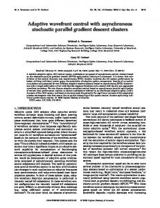
delay line [14]. The limit of this technique is the accessible time delay given by the length to which a broadband pulse can be temporally stretched. High-speed asynchronous optical sampling (ASOPS) is an ultrafast TDS method that operates without mechanical scanner, permits multi-kHz scan rates, allows fast measurements directly at the shot-noise limit, and additionally offers the straightforward possibility to perform two-color pump-probe measurements [15–17]. Instead of a mechanical scanner, a high-speed ASOPS system employs two pulsed lasers with a small repetition rate offset ∆f to accomplish time-delay scanning without motion of mechanical parts. One laser with repetition rate f + ∆f serves as the pump laser, the other with repetition rate f serves as the probe laser in the experiment. As a result of the offset ∆f, the time delay τ between pump- and probe-pulsepairs is linearly ramped between zero and the inverse of f + ∆f as a function of real-time t: τ(t) = (∆f × t) /(f + ∆f). This transformation from a time-delay axis τ to a real-time axis t is inherent to high-speed ASOPS. It linearly stretches ultrafast processes by a factor (f + ∆f)/∆f and makes them accessible to fast data acquisition electronics. The scan rate ∆f can be arbitrarily chosen and is only limited by the desired time resolution ∆τ. ∆τ is theoretically given by the maximum of the following three quantities: the laser pulse duration; the pulsepair-to-pulse-pair time-delay increment ∆f/(f × (f + ∆f)); and the time resolution given by the available bandwidth BW of the signal detection ∆f/(BW × (f + ∆f)). Here, we use femtosecond lasers with 45 fs pulse duration and repetition rates of 1 GHz. Available analog-to-digital (A/D) converters with >14 Bit resolution (typically required to measure at shot-noise limit) offer bandwidths of BW≈100 MHz. Thus, at 1 GHz repetition rate a time resolution below 50 fs can theoretically be achieved at scan rates of up to 5 kHz. At such scan rates, a measurement is completed before typical technical noise has an effect and data acquisition directly at the shot-noise limit is possible. For comparison, the same scheme with more common femtosecond lasers with f = 80 MHz would require ∆f = 320 Hz to achieve a theoretical resolution of 50 fs and would thus not permit avoiding influence of technical laser noise. This highlights the benefits of repetition rates in the GHz range for ASOPS. In our previous demonstrations of high-speed ASOPS, however, we have not been able to achieve the theoretical time resolution but were limited to 160 fs due to residual timing jitter between the offset-locked lasers that resulted in significant deviations from the ideal time-delay function τ(t) = (∆f × t) /(f + ∆f) [16]. Here, we demonstrate for the first time a repetition rate offset-locking method operating at the tenth harmonics of the repetition rates combined with an offset-frequency definition based on direct-digital-synthesis (DDS) electronics. This method permits a laser-pulse-duration-limited time resolution of 45 fs over the full 1 ns measurement window, i.e. an improvement by a factor of three compared to our previous approach [16]. The high time resolution is verified by resolving optically excited coherent 13.2 THz optical phonons in ZnO. In a more application-oriented example, we use our system for rapid and sensitive mapping of the layer period and total stack thickness of soft-X-ray multilayer mirrors via detection of acoustic phonons and acoustic echoes following optical excitation. 2. High-speed ASOPS setup The high-speed ASOPS setup is shown in Fig. 1. Core elements are two 1 GHz repetition rate Ti:sapphire lasers sharing a common housing milled from a solid aluminum block (Gigajet TWIN, Gigaoptics GmbH) which are operated in a master-slave configuration. The repetition rate of the master laser is free-running and the slave laser repetition rate is stabilized with an offset ∆f using a phase-locked loop (PLL). Both lasers deliver ≈800 mW of average output power at center wavelengths independently tunable between 750 nm and 850 nm. The pulse durations are ≈45 fs. A small portion of the output power of each laser (≈5 mW) is split off with beam-splitters BS3 and BS4 and focused onto 10-GHz bandwidth photodiodes PD1 and PD2 to detect the repetition rates and their harmonics. The photodiode signals are used to phase-coherently generate an error signal representing deviations of the repetition rate-offset ∆f from the desired value ∆fset. The electronics to generate this error signal are summarized in the gray box in Fig. 1 and are referred to as the error signal unit (ESU) in the following. The #123136 - $15.00 USD
(C) 2010 OSA
Received 21 Jan 2010; revised 4 Mar 2010; accepted 4 Mar 2010; published 10 Mar 2010
15 March 2010 / Vol. 18, No. 6 / OPTICS EXPRESS 5976
ESU selects the 10th harmonics of the repetition rates of the master 10 × f and slave lasers 10 × (f + ∆f) with bandpass filters BP1 and BP2 (10 GHz center frequency, 1 GHz bandwidth) and adds those signals to the outputs of two DDS integrated circuits (ICs) using doublebalanced mixers M1 and M2. The DDS elements operate with a 48-bit tuning word, permitting a practically arbitrary choice of the output frequency (tuning step size ~4 µHz), and with a maximum clock frequency of 1 GHz. The DDS-ICs use the master repetition rate f, that has been split off before BP1 using a power splitter (PS), as clock frequency. The output
Fig. 1. Setup of the high-speed ASOPS system. The gray box exhibits the improved error signal unit scheme for the repetition rate-offset stabilization. BS1 to BS4: optical beam-splitters, PD1 to PD3: amplified photodiodes, PS: power splitter, DDS1 and DDS2: direct digital synthesis components, BP1 to BP4: electronic band-pass filters, M1 to M3: electronic mixers, HVA: high voltage amplifier, f: master repetition rate, f + ∆f: slave repetition rate, ∆fset: desired offset frequency. Straight lines correspond to optical beams, dashed lines to electronic connections. The red and blue formulas illustrate the corresponding frequencies inside the error-signal unit branches.
frequency of DDS-IC DDS1 is set to f/2 and that of DDS-IC DDS2 is set to f/2 - (10 × ∆fset). The outputs of mixers M1 and M2 are bandpass filtered (BP3 and BP4, 10.5 GHz center frequency, 100 MHz bandwidth) to isolate the sum-frequency products. Finally, mixer M3 is used as analog phase-detector to generate an error signal that is proportional to the phase between the outputs of BP3 at (10 × f) + f/2 and BP4 at 10 × (f + ∆f) + f/2- (10 × ∆fset). The error signal is amplified and low-pass filtered with a loop filter and further amplified by use of a high voltage amplifier (HVA) to control the slave repetition rate via a weight reduced cavity mirror mounted on a high-bandwidth piezoelectric transducer (disc with 2 mm thickness, 10 mm diameter, resonant frequency >100 kHz). The highest possible feedback-loop bandwidth is ~12 kHz, determined by the combined response function of the PLL components. When the PLL is closed, i.e. the error signal is forced to a DC voltage, ∆f equals ∆fset and the lasers are offset-locked in a phase-coherent manner. The ESU contains two major improvements compared to our previous approach [16]. Firstly, using the 10th harmonics of the laser repetition rates allows an enhancement of the feedback loop sensitivity towards timing jitter by a factor of 10 compared to using the first harmonics and thus enables a tighter PLL. Secondly, employing a DDS-IC-based definition of ∆f instead of using analog single-sideband generators (SSBG) eliminates problems with sidebands separated by ∆f and higher harmonics of ∆f from the carrier, as typically created by SSBGs [16]. These sidebands previously caused a significant miscalibration of the time-axis if the feedback loop bandwidth approached ∆f (typically 2-10 kHz) and thus limited the applicable feedback loop bandwidth to values well below ∆f. In contrast, the system presented here permits to exploit the full available PLL feedback bandwidth of ~12 kHz, an essential ingredient to achieve a tighter PLL. Approximately 700 mW of average power from each laser is reflected by BS3 and BS4 and is used for ultrafast time-domain spectroscopy as described previously [15,16]. The pump
#123136 - $15.00 USD
(C) 2010 OSA
Received 21 Jan 2010; revised 4 Mar 2010; accepted 4 Mar 2010; published 10 Mar 2010
15 March 2010 / Vol. 18, No. 6 / OPTICS EXPRESS 5977
laser induced transient reflectivity changes of a sample are probed with the probe laser that is detected with a 125-MHz bandwidth photoreceiver with a Si-pin photodiode as the photoactive element. The photoreceiver output is digitized with a 100-MS/s 14-Bit A/D converter. The A/D converter is triggered by a cross-correlation signal between master- and slave laser generated via two-photon absorption in a GaP diode (PD3) using split off beams from both lasers (BS1 and BS2) with ≈100 mW average power. It should be pointed out that the photoreceiver has an AC-coupled signal output with 40 V/mA and a DC monitor output with 1 V/mA transimpedance gain. This allows to amplify the signal to a level at which the detection shot-noise exceeds the A/D converter noise (~0.3 mV peak-to-peak) enabling measurements directly at shot-noise limit and at the same time avoiding saturation of the transimpedance amplifier and A/D converter with the DC contribution. The low-frequency 3dB cutoff of the signal output is at 25 kHz. Thus, if slow signal contributions with Fourier content below (f × 25 kHz)/∆f (e.g. 5 GHz in the case of ∆f = 5 kHz) are to be faithfully resolved (e.g. slow electronic signal decay), ∆f must be set to values greater than 25 kHz. The AC-coupling has no effect on experiments focussing on fast signal dynamics as discussed in the following. 3. High-speed ASOPS characterization Key performance parameters of a high-speed ASOPS system are time resolution and residual error of the time-axis calibration. In contrast to conventional TDS systems, these can depend on the time delay, i.e. on the position within the measurement window. A characterization is performed using a cross-correlation setup as shown in Fig. 2(a). The beam from the master laser is split into two arms and recombined using beam-splitters BS5 and BS6. One arm of the master laser path has a retro reflector (RR) on a variable delay-stage in order to form a double pulse with well-defined pulse spacing. The delay-stage with 20 cm travel range has been calibrated independently with ≈10−6 relative precision by measuring the pulse-to-pulse distance of a single laser with well-known repetition rate in an autocorrelation setup. The pulse train from the slave laser is non-collinearly overlapped with the double pulses from the master laser in a BBO crystal to create a sum-frequency signal that is detected with an amplified photodiode (PD). Figure 2(b) shows a typical transient, 4000-times averaged, for a fixed translation stage position. The signal at 0-ps, labelled “trigger”, corresponds to the master pulse train transmitting both beam-splitters BS5 and BS6. This signal is used to trigger the data acquisition. The position of the second peak, labelled “cross-correlation”, changes with the retro reflector position and defines the position within the 1 ns measurement window at which the characterization is performed. The full width at half maximum (FWHM) of the averaged “cross-correlation” signal divided by a deconvolution factor 1.54 for the squaredhyperbolic secant pulses from the lasers is a measure of the time resolution of the high-speed ASOPS system at a given time-delay position. Figure 2(c) shows the time resolution evaluated at 150 equidistant positions within the 1 ns window for ∆f = 2 kHz, 3 kHz and 5 kHz. A time resolution of 50 fs is obtained for ∆f = 5 kHz throughout the full measurement window. Here,the time resolution limitation is given by the available signal detection bandwidth BW to ∆f/(BW × (f + ∆f)) = 50 fs. For ∆f = 3 kHz and ∆f = 2 kHz the time resolution reaches the pulse duration limit of 45 fs. This shows that timing jitter is not the limiting factor of the time resolution as has been the case in previous experiments [16]. The slight increase of the time resolution by ≈4 fs at time delays