JOURNAL OF APPLIED PHYSICS
VOLUME 95, NUMBER 5
1 MARCH 2004
High-speed optical switching based on diffusive conduction in an optical waveguide with surface-normal optical control V. A. Sabnis,a) H. V. Demir,b) M. B. Yairi, J. S. Harris, Jr., and D. A. B. Miller Edward L. Ginzton Laboratory and Solid State and Photonics Laboratory, Stanford University, 450 Via Palou, Stanford, California 94305
共Received 2 September 2003; accepted 2 December 2003兲 We report a surface-normal optically controlled waveguide switch made of a p-i-n diode that utilizes optically induced voltage screening to turn on and diffusive conduction to turn off. We examine theoretically diffusive conduction in these switches and show that this mechanism offers the possibility of creating optical switches operating at several tens of GHz. As a proof-of-concept demonstration, we present experimental results of wavelength-converting, optical switching at frequencies up to 2.5 GHz in a multiple-quantum-well, GaAs-based waveguide device using milliwatt-level switching powers. Optimized arrays of these devices can be used for high-speed, multichannel wavelength conversion and optical regeneration in wavelength-division-multiplexed systems. © 2004 American Institute of Physics. 关DOI: 10.1063/1.1643789兴
I. INTRODUCTION
by the signal beam. In this work, we investigate optical switching using diffusive conduction in a waveguide modulator, as shown in Fig. 1, and show that high extinction ratio, high-speed operation, compatible with telecommunication network data rates, is possible. We present proof-of-concept experimental results demonstrating switching with substantially higher extinction ratios compared to our previous work at speeds up to 2.5 GHz in a GaAs-based waveguide device.
All-optical information transfer schemes1– 8 have recently been investigated as efficient, compact, low-cost alternatives to conventional optical-electronic-optical 共o-e-o兲 conversion for performing 共partial兲 optical regeneration, wavelength conversion, and switching in wavelengthdivision-multiplexed systems. Although these investigations have yielded high performance results, these techniques are either not amenable to integration with electronics or cannot be conveniently scaled into two-dimensional arrays for multichannel operation. In this article, we introduce a surfacenormal optically controlled waveguide switch, comprised of a single semiconductor p-i-n diode containing multiple quantum wells, that can perform wavelength conversion and 共partial兲 optical regeneration, while requiring only milliwattlevel optical and electrical switching powers. Its architecture and electronic reconfigurability allow for two-dimensional scalability and seemless integration with electronics, introducing the ability to create a multichannel, electrically reconfigurable, wavelength-converting, optical crossbar switch. Its operation is based on cross electroabsorption modulation from optically induced changes in the electric field across multiple quantum wells in a diode, through, for example, the quantum confined Stark effect.9 Its switching dynamics rely on voltage screening across the diode through the vertical separation of injected photocarriers and voltage decay along the length of the diode through lateral voltage diffusion, also known as diffusive conduction.10 Our group has previously demonstrated diffusive conduction-based optical switches operating at speeds up to 50 GHz using low control beam energies.11,12 These devices were realized in vertical modulators, and exhibited low extinction ratios due to the short active region length traversed
II. DEVICE CONCEPT
As depicted in Fig. 1共a兲, two optical inputs are incident on the switch: a control and a signal. The control input is a
a兲
Author to whom correspondence should be addressed; electronic mail:
[email protected] b兲 Electronic mail:
[email protected] 0021-8979/2004/95(5)/2258/6/$22.00
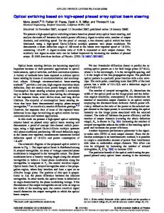
FIG. 1. 共a兲 A schematic, and 共b兲 an SEM picture of the single diode waveguide switch. 2258
© 2004 American Institute of Physics
Downloaded 15 Mar 2004 to 171.64.85.97. Redistribution subject to AIP license or copyright, see http://jap.aip.org/jap/copyright.jsp
Sabnis et al.
J. Appl. Phys., Vol. 95, No. 5, 1 March 2004
modulated beam that carries a data stream and illuminates the entire length of the waveguide from above, whereas the signal input is a steady continuous-wave beam that is coupled into the waveguide from the side. The function of the switch is to modulate the signal output power with the control input by optically controlling the electroabsorption of the switch so that the control data is encoded onto the signal output, creating a noninverting optical switch. The switching relies on nonlinear electroabsorption of quantum wells, located in the core of the waveguide, resulting in a nonlinear optical transmission gate that, in principle, reshapes the output signal.3 Furthermore, wavelength conversion arises naturally from this process when different wavelengths for the signal and control beam inputs are used. Quantum wells placed in the core of the waveguide are designed such that their absorption at the signal wavelength changes as a function of the electric field across the well layers.9 On the other hand, at the control wavelength, the entire intrinsic core region is designed to be absorptive, regardless of the electric field across the device. The device is set, initially, to be strongly absorbing at the signal beam wavelength by applying an appropriate reverse bias across the waveguide diode. Switching occurs by applying the control beam, creating carriers in the intrinsic region of the device. As these photogenerated carriers vertically separate across the core region due to the reverse bias, the net voltage across the electroabsorptive layers is reduced due to field screening, modifying the transmission of the signal beam. Thus, data are transferred from the control beam to the signal beam. This optically induced voltage shielding decays through diffusive conduction, returning the switch to its initial state. In effect, the switch functions simultaneously as a photodetector and an optical modulator, performing efficient o-e-o conversion in a single, ultracompact device without the use of conventional electronics. In order to exploit the high-speed voltage dynamics of diffusive conduction, we designed the switch, as shown in the scanning electron micrograph 共SEM兲 of Fig. 1共b兲, to consist of a ridge waveguide and a local capacitor attached to the side of the waveguide. Unlike conventional, electrically driven, waveguide electroabsorption modulators, the top of the waveguide is not metalized, allowing for precise control of the diffusive conduction dynamics through the epitaxial layer design to achieve a desired bit rate operation, in addition to providing optical access for the surface-normalilluminating control beam. The local capacitor, consisting of a large-area, reverse-biased, mesa diode, electrically connects the voltage bias supply to one point along the length of the waveguide. Thus, we ensure that one-dimensional diffusive conduction governs the voltage dynamics of our switch by: 共1兲 using a narrow, ridge waveguide where the controlbeam-induced shielding voltage can propagate along the length of the waveguide, 共2兲 constructing the waveguide from a reverse-biased, p-i-n diode, where the conductance and inductance of such a structure are negligible, effectively creating a lossy RC transmission line, and 共3兲 placing the local capacitor immediately adjacent to the waveguide so that the internal switching response time of the device is significantly shorter than the RC response time of the exter-
2259
nal circuit. The use of the local capacitor confines the highspeed, optoelectronic switching within the waveguide only, without loading from the external circuitry. Under these conditions, the switching response time is predominantly determined by vertical carrier transport of the control-beamgenerated electrons and holes across the intrinsic region and lateral diffusive conduction along the waveguide of the shielding voltage created by the carrier sweepout. Consequently, the device requires modest optical switching powers since only the small, distributed capacitance along the length of the waveguide needs to be charged and discharged. Additionally, since only a dc bias is required for this device, unlike the requirements for conventional high-speed optical modulators and photodetectors, complex electrical interconnection issues such as the use of transmission lines and microwave packaging are eliminated. For intrinsic region thicknesses on the order of 1 m or less, carrier sweepout, and hence the creation of the voltage shielding, can occur rapidly on a time scale of less than 10 ps. To guarantee both fast temporal device response and strong optical transmission modulation, the diffusive conduction process that neutralizes this voltage shielding must be properly engineered. The voltage dynamics of onedimensional diffusive conduction obey the diffusion equation given by d 2V dV ⫽D 2 , dt dx
共1兲
where D⫽1/R ᐉ C ᐉ . Here R ᐉ is the sum of the resistances per unit length of the diode p and n regions only, while C ᐉ is the capacitance per unit length of the diode. The distributed internal resistance and capacitance of the waveguide diode and the bias point location determine the rate of voltage decay. These parameters are controlled through the epitaxial doping and thicknesses of the p- and n-cladding layers, the thickness of the diode intrinsic region, the waveguide width, and the mask layout of the switch, respectively. Equation 共1兲 assumes a constant capacitance per unit length as a function of time. Although application of the control beam modifies the voltage across the diode, and, hence, the capacitance of the structure, our calculations show that for intrinsic region voltage variations up to 10 V, which far exceeds the controlbeam-induced shielding voltage necessary for strong optical transmission modulation in a wide variety of p-i-n diode structures suitable for these types of optical switches, the capacitance variation is on the order of only a few percent. Hence, Eq. 共1兲 accurately describes the optically induced voltage dynamics in such structures. The architecture of the switch allows us to invoke two boundary conditions: 共1兲 there is no voltage perturbation at x⫽0 共bias point兲 due to the presence of the local capacitor, which holds a steady voltage approximately equal to the supply voltage, and 共2兲 the derivative of the voltage perturbation at x⫽L 共the other end of the waveguide兲 is set to zero since an external current path is not available at this location. For simplicity of modeling, we assume that the initial voltage perturbation is uniform 共except at x⫽0) over the length of the waveguide, although the control beam, and hence the
Downloaded 15 Mar 2004 to 171.64.85.97. Redistribution subject to AIP license or copyright, see http://jap.aip.org/jap/copyright.jsp
2260
Sabnis et al.
J. Appl. Phys., Vol. 95, No. 5, 1 March 2004
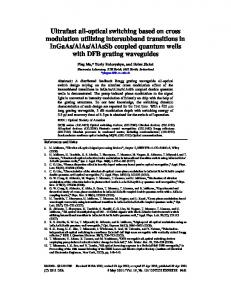
FIG. 2. Diffusive conduction impulse response for an end-located bias point device (L⫽300 m, bias point at x⫽0).
FIG. 3. Diffusive conduction impulse response for a center-located bias point device (L⫽300 m, bias point at x⫽150 m).
III. THEORETICAL RESULTS
initial voltage shielding profile, will be Gaussian shaped. Under these circumstances, for a bias point located at x⫽0 共one end of the waveguide兲, as shown in the top of Fig. 2, the diffusive conduction impulse response, V(x,t), of the optically-induced shielding voltage created by the control beam will behave as ⬁
V 共 x,t 兲 ⫽
sin共  m x 兲 ⫺D  2 t 4⌬V m , e m⫽1 2m⫺1
兺
共2兲
where ⌬V is the optically induced voltage perturbation at t ⫽0, L is the length of the waveguide, and  m is given by (2m⫺1) /2L. Figure 2 shows the impulse response for a 1 V optically induced shielding voltage in a 300-m-long waveguide using nominal design parameters of R ᐉ ⫽16 ⍀/ m and C ᐉ ⫽0.23 fF/ m; as will be detailed in the experimental results section, these parameters correspond to the device that we experimentally investigated. As time progresses, points near the bias point (x⫽0) are discharged very rapidly on the order of a few picoseconds since any voltage perturbation can be quickly neutralized due to the close proximity of the local capacitor. Points further down the waveguide subsequently discharge in a daisy chain fashion. The response time for a particular location can take a few to hundreds of picoseconds depending on the distance from the bias point. In this simulation, the oscillations observed in the starting voltage profile, corresponding to t⫽0, result from the truncation of the infinite series in Eq. 共2兲 to 100 terms. As shown in Figs. 2 and 3, by simply placing the bias point at the center of the waveguide, the response time for all points can be significantly decreased. For this particular example, the device behaves as two back-to-back 150-m-long waveguides, each obeying Eq. 共2兲. In this case all points along the waveguide are discharged over a duration of only ⬃100 ps.
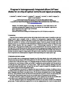
To understand the performance capabilities of this device, we developed a simulation model that includes the photogeneration of electrons and holes in the intrinsic region from the control beam, vertical carrier transport across the intrinsic region, one-dimensional lateral diffusive conduction as described above, and subsequent modification of the voltage across the quantum wells through the use of Poisson’s equation. By using this simulation model in conjunction with empirically measured quantum well electroabsorption data, we model the optical modulation characteristics of these switches. Figure 4 shows the 3 dB optical bandwidths of devices with lengths ranging from 25 to 500 m for endlocated and center-located bias points, with the same nominal R ᐉ and C ᐉ used in Figs. 2 and 3. For device lengths below 25–50 m, corresponding to devices with very large 3 dB bandwidths, the inductance per unit length of the waveguide cannot be ignored and should be accounted for through appropriate modification of the analytical solution given in
FIG. 4. A 3 dB optical bandwidth of different length optically controlled waveguide switches (R ᐉ ⫽16 ⍀/ m and C ᐉ ⫽0.23 fF/ m).
Downloaded 15 Mar 2004 to 171.64.85.97. Redistribution subject to AIP license or copyright, see http://jap.aip.org/jap/copyright.jsp
Sabnis et al.
J. Appl. Phys., Vol. 95, No. 5, 1 March 2004
2261
IV. EXPERIMENTAL RESULTS
FIG. 5. Simulation of 10 Gb/s nonreturn-to-zero operation 共for a 2-m-wide ⫻250-m-long, center bias point device using an average incident control power of 4.65 mW at control⫽822 nm and signal⫽864 nm with R ᐉ ⫽16 ⍀/ m and C ᐉ ⫽0.23 fF/ m).
Eq. 共2兲 or implementation of a numerical solution in place of Eq. 共2兲. As expected, the center-located bias point devices offer significantly higher operating bandwidths compared to the end-located bias point devices. For a center-located bias point device, the local capacitor simultaneously discharges both halves of the waveguide, while for an end-located bias point device, the local capacitor must discharge the entire waveguide serially. In effect, the voltage diffusion length for center-located bias point devices is half as large as the diffusion length for end-located bias point devices. In both cases, modulation bandwidths on the order of tens of GHz can be achieved. For center-located bias point devices, reasonable device lengths of 250 and 120 m are required for 10 and 40 GHz, respectively, offering the possibility of operation at current and future optical network data rates. In these simulations, the 3 dB optical bandwidth closely matches the electrical bandwidth of the switches because the signal wavelength is far from the absorption peak of the quantum wells. Since the electroabsorption in this region is not highly nonlinear, the 3 dB optical bandwidth closely matches the electrical bandwidth of these switches. Using a signal wavelength closer to the absorption peak results in stronger electroabsorption, with a greater nonlinear absorption change with voltage, and optical bandwidths significantly larger than the electrical bandwidth. Under this circumstance, the transmitted optical signal is reshaped with respect to the control beam input, although this comes at the cost of increased insertion loss through the device. Additional simulations showed these switches can offer ⬎10 dB signal extinction ratios over a wide range of operating frequencies for control beam input powers on the order of a few milliwatts. As an example, Fig. 5 shows a simulation of a 2-m-wide by 250m-long, center bias point device operating at 10 Gb/s using an average input control beam power of only 4.7 mW. Note that although diffusive conduction discharges points near the bias point very rapidly, we found that this behavior results in only a few dB penalty in insertion loss and extinction ratio when compared to a conventional, uniformly charged, electroabsorption modulator driven with the same average voltage swing.
For a proof-of-concept demonstration, we fabricated a device consisting of a 2-m-wide by 300-m-long, GaAsbased, p-i-n diode, ridge waveguide designed for single transverse mode operation for wavelengths longer than 860 nm. The device was grown on an n ⫹ GaAs substrate using molecular beam epitaxy. The bottom cladding layer consists of 2-m-thick, n-doped (5⫻1017 cm⫺3 ) Al0.08Ga0.92As. The active electroabsorption material comprises 8 – 100 Å GaAs/30 Å Al0.27Ga0.73As quantum wells, with a heavy hole-electron exciton state near 850 nm, and is surrounded by two 4000 Å layers of nominally undoped Al0.05Ga0.95As. The resulting intrinsic region thickness is 0.907 m. The upper cladding contains a 1-m-thick, p-doped (5⫻1017 cm⫺3 Be兲 Al0.08Ga0.92As layer followed by a 1-m-thick, p ⫹ (2⫻1019 cm⫺3 Be兲 Al0.08Ga0.92As layer. The upper cladding layers are designed to have a band gap at 814 nm, while the two 4000 Å Al0.05Ga0.95As layers in the intrinsic region are designed to have a band gap at approximately 833 nm. Hence, the two Al0.05Ga0.95As layers efficiently absorb control beam wavelengths between 814 and 833 nm. This epitaxial layer design enables the waveguide to function as a surface-illuminated photodetector for the control beam between 814 and 833 nm. Since the quantum wells are engineered to have an absorption band edge at 850 nm, optical transmission of signal beams with wavelengths longer than 850 nm are efficiently modulated by varying the electric field across the quantum wells. Furthermore, this allows the device to serve as an efficient electroabsorption modulator for the signal beams at wavelengths longer than 850 nm. Since we used a doped substrate, the distributed resistance of the device is determined by the sheet resistance of the p-doped cladding layers. The combination of the 5 ⫻1017 cm⫺3 Be-doped and 2⫻1019 cm⫺3 Be-doped p-cladding layers provides a sheet resistance of 32 ⍀/square, or equivalently 16 ⍀/m for a 2-m-wide waveguide, as used in the theoretical simulations. The 0.907-m-thick intrinsic region yields a capacitance per unit length of 0.23 fF/m for a 2-m-wide waveguide, also used in the simulations. A continuous-wave Ti-sapphire laser operating at 868 nm was used as the signal beam. The signal beam was coupled into and out of the waveguide using fiber collimators and aspheric lenses. In Fig. 6, we plot the fiber-to-fiber transmission as a function of the applied electrical bias across the waveguide diode at the signal wavelength of 868 nm. The zero-bias fiber-to-fiber transmission was approximately ⫺10 dB. Applying biases greater than 5 V results in significant increases in absorption and correspondingly strong decreases in optical transmission. A diode laser operating at 822 nm was used as the control beam to illuminate the waveguide from above. The control beam was initially circularized using an anamorphic prism pair and subsequently elongated into an elliptical beam approximately 5 m wide by 300 m long using a telescope consisting of a cylindrical lens and microscope objective. With an incident continuous-wave control-beam power of 7.8 mW, corresponding to 4.2 mW
Downloaded 15 Mar 2004 to 171.64.85.97. Redistribution subject to AIP license or copyright, see http://jap.aip.org/jap/copyright.jsp
2262
Sabnis et al.
J. Appl. Phys., Vol. 95, No. 5, 1 March 2004
FIG. 6. Input fiber to output fiber transmission as a function of applied reverse dc bias at signal⫽868 nm.
FIG. 7. Dynamic switching operation: modulation at 2.5 GHz 共a兲 control input at 822 nm, 共b兲 resulting signal output at 868 nm.
absorbed power in the waveguide, and a reverse bias of 7 V applied across the waveguide, a 7.7 dB signal transmission change was optically induced. This corresponds to an effective voltage swing across the device of approximately 1.78 V, which is comparable to the 1 V swings traditionally provided by rf drivers that are used to encode electrical data onto the output of conventional, electroabsorption modulators.13 The degree of signal transmission change depends on the signal transmission versus voltage characteristics, the operating electrical bias, and the magnitude of the optically induced voltage change. Increasing the control beam power will lead to effectively larger voltage swings increasing the signal modulation depth. For signal wavelengths shorter than 868 nm, but larger than the heavy hole-electron exciton wavelength 共850 nm兲, the transmission change as a function of voltage is stronger, although at the cost of increased insertion loss. Thus, in this wavelength range, for a given control power, we observed a much larger extinction ratio but lower overall transmission. The opposite behavior is found for signal wavelengths longer than 868 nm. For purposes of demonstration, the device performance at a signal wavelength of 868 nm presented a good compromise between insertion loss and contrast ratio, while maintaining single mode waveguide operation. For dynamic operation of the device, we directly modulated the laser diode under large-signal conditions at different frequencies up to 2.5 GHz. Optically controlled switching using a maximum available control beam power of 2.4 mW at a maximum available modulation rate of 2.5 GHz is shown Fig. 7. In response to the modulated control inputs, we observed the initially continuous-wave signal beam to be modulated at the output of the waveguide at the corresponding control modulation frequencies, demonstrating wavelength-converting optical modulation of the 868 nm signal beam with the 822 nm control beam. The signal output modulated at 2.5 GHz is presented in Fig. 6共b兲. The signal beam output is slightly distorted with respect to the control beam input due to mechanical instability and real-time disturbances in our very sensitive waveguide alignment setup. It was not possible to investigate the device’s modulation performance beyond 2.5 GHz due to test equipment limitations, although our theoretical model predicts a 3 dB electrical bandwidth of approximately 5 GHz.
During optical switching, the ability to electrically enable or disable the device was also demonstrated. For example, if the device bias voltage is removed or slightly forward biased, the signal beam is strongly transmitted and the optical switching is disabled despite the presence of the control beam. Without an applied bias across the device, the photogenerated carriers created by the control beam will not separate sufficiently and hence will not create a large enough shielding voltage necessary for significant transmission modulation. Furthermore, as shown in Fig. 6, since the transmission versus voltage is approximately flat near V⫽0, any optically induced shielding voltage created by the presence of photogenerated carriers cannot appreciably alter the signal beam transmission. The ability to electrically enable and disable the optical switching means that this device may be integrated with control electronics; such control electronics could be used in a feedback loop to fine tune the device switching characteristics when the device is enabled or be used to turn off the optical switching when necessary. Such a capability also allows for electrically reconfigurable array operation of these devices since, in such an application, independent control of the individual switches is required. V. CONCLUSIONS
In this work, we presented a wavelength-converting, surface-normal optically controlled, waveguide switch based on diffusive electrical conduction and demonstrated proofof-concept wavelength conversion at speeds up to 2.5 GHz. Through proper design of the material parameters and device geometry to control the diffusive conduction behavior, this device can be engineered to operate at several tens of GHz, while requiring only mW-level optical switching powers. We believe that their electronic configurability and potential for two-dimensional scalability make these devices attractive for high-density switching architectures in wavelength-divisionmultiplexed systems that require wavelength conversion and 共partial兲 optical regeneration. 1
J. M. Yates, M. P. Rumsewicz, and J. P. R. Lacey, IEEE Comm. Surv. 2, 2 共1999兲. S. J. B. Yoo, IEEE J. Light. Technol. 14, 955 共1996兲. 3 T. Otani, T. Miyazaki, and S. Yamamoto, IEEE Photonics Technol. Lett. 12, 431 共2000兲. 2
Downloaded 15 Mar 2004 to 171.64.85.97. Redistribution subject to AIP license or copyright, see http://jap.aip.org/jap/copyright.jsp
Sabnis et al.
J. Appl. Phys., Vol. 95, No. 5, 1 March 2004 4
J. M. Wiesenfeld, B. Glance, J. S. Perino, and A. H. Gnauck, IEEE Photonics Technol. Lett. 5, 1300 共1993兲. 5 F. Liu, X. Zheng, L. Oxenloewe, R. Pedersen, P. Jeppsen, J. Fraser, J. Bainbridge, and M. Cox, Optical Fiber Communications Conference 共OSA Technical Digest, Optical Society of America, Washington, DC, 2001兲, WK4-1. 6 S. Hojfeldt, S. Bischoff, and J. Mork, J. Lightwave Technol. 18, 1121 共2000兲. 7 S. Kodama, T. Yoshimatsu, and H. Ito, Electron. Lett. 39, 383 共2003兲. 8 M.-S. Chou, I. Brener, M. M. Fejer, E. E. Chaban, and S. B. Christman, IEEE Photonics Technol. Lett. 11, 653 共1999兲.
2263
9
D. A. B. Miller, D. S. Chemla, T. C. Damen, A. C. Gossard, W. Wiegmann, T. H. Wood, and C. A. Burrus, Phys. Rev. Lett. 53, 2173 共1984兲. 10 G. Livescu, D. A. B. Miller, T. Sizer, D. J. Burrows, J. Cunningham, A. C. Gossard, and J. H. English, Appl. Phys. Lett. 54, 748 共1989兲. 11 M. Yairi, C. W. Coldren, D. A. B. Miller, and J. S. Harris, Jr., Appl. Phys. Lett. 75, 597 共1999兲. 12 M. Yairi, H. V. Demir, and D. A. B. Miller, Opt. Quantum Electron. 33, 1035 共2001兲. 13 F. Devaux, F. Dorgeuille, A. Ougazzaden, F. Huet, M. Carre´, A. Carenco, M. Henry, Y. Sorel, J.-F. Kerdiles, and E. Jeanney, IEEE Photonics Technol. Lett. 5, 1288 共1993兲.
Downloaded 15 Mar 2004 to 171.64.85.97. Redistribution subject to AIP license or copyright, see http://jap.aip.org/jap/copyright.jsp