AbstractâHigh-speed recursive filter structures for interpola- tion and decimation with factors of two, and quadrature mirror filter (QMF) banks with perfect ...
16
IEEE TRANSACTIONS ON CIRCUITS AND SYSTEMS—II: ANALOG AND DIGITAL SIGNAL PROCESSING, VOL. 46, NO. 1, JANUARY 1999
High-Speed Recursive Filter Structures Composed of Identical All-Pass Subfilters for Interpolation, Decimation, and QMF Banks With Perfect Magnitude Reconstruction H˚akan Johansson, Member, IEEE, and Lars Wanhammar, Member, IEEE
Abstract—High-speed recursive filter structures for interpolation and decimation with factors of two, and quadrature mirror filter (QMF) banks with perfect magnitude reconstruction, are proposed. The structures are composed of identical all-pass subfilters that are interconnected via extra multipliers. For the case of interpolation and decimation filters, the overall transfer function corresponds in the simplest case to several half-band infinite-impulse response (IIR) filters in cascade. To achieve a smaller passband ripple than for a cascade design, a design procedure that has been used earlier for single-rate filters is used. In this approach, the design is split into designs of a prototype finite-impulse response (FIR) filter and a half-band IIR filter. For the case of QMF banks, the design is again separated into designs of a prototype FIR filter and a halfband IIR filter. One major advantage of the proposed filter structures over the corresponding conventional (half-band filter) structures is that the required coefficient word length for the allpass filters is substantially reduced, implying that the maximal sample frequency can be substantially increased for a given VLSI technology. Further, for interpolation and decimation, the arithmetic complexity may be reduced in comparison with both the conventional structures and straightforward cascade structures. Simple recurrence formulas for computation of the interconnecting multipliers, given the overall transfer function, are derived. Several examples are included which compare the proposed structures with the corresponding conventional and straightforward cascade structures.
Fig. 1. Interpolation and the corresponding polyphase realization.
I. INTRODUCTION
O
VER the past decades, a large number of filter structures for interpolation and decimation have been introduced. Two major objectives have been to develop structures requiring few arithmetic operations per sample, as well as having good properties under finite-arithmetic conditions. To obtain as low an arithmetic complexity as possible, it is beneficial to rewrite the transfer function in its polyphase form according to (1) are referred to as the polyphase components. where The actual filtering can then be performed at the lower Manuscript received February 28, 1997; revised June 8, 1998. This paper was recommended by Associate Editor B. A. Shenoi. The authors are with the Department of Electrical Engineering, Linkoping University, SE-58183 Linkoping, Sweden. Publisher Item Identifier S 1057-7130(99)01465-2.
Fig. 2. Decimation and the corresponding polyphase realization.
sampling rate by using the corresponding polyphase structures for interpolation and decimation, as shown in Figs. 1 and 2, respectively. Generally, the most efficient polyphase converters are obtained by letting the polyphase components be all-pass subfilters [1]. The overall filters are in this case referred to as th-band infinite-impulse response (IIR) filters. The all-pass subfilters can be realized as a cascade of first- and second-order sections. This results in parallel and modular filter algorithms, which is attractive from an implementation point of view. In addition, by using wave
1057–7130/99$10.00 1999 IEEE
JOHANSSON AND WANHAMMAR: HIGH-SPEED RECURSIVE FILTER STRUCTURES COMPOSED OF IDENTICAL ALL-PASS SUBFILTERS
17
Fig. 3. Cascade realization where only the first stage works at the low sampling frequency.
digital filters (WDF’s) for the all-pass subfilters, it is possible to maintain stability under finite-arithmetic conditions [2], [3]. In this paper, we are concerned with the special case where , in which the overall filter is a half-band IIR filter. Using WDF’s for the all-pass subfilters in this case results in the well-known bireciprocal lattice WDF [3]–[5]. However, filters composed of all-pass subfilters in parallel have a drawback in having a high-coefficient sensitivity in the stopband. The required coefficient word length is, roughly, proportional to the required stopband attenuation [1]. For stringent requirements on the stopband attenuation, this implies very long coefficients. This has a large effect on implementations of these filters. For signal processor implementations where the data and coefficient word lengths cannot exceed a certain allowable length, it may become impossible to use these filters straightforwardly. For VLSI implementations where it is possible to benefit by short data word lengths and simple coefficients, the cost to implement the coefficients increases as the word lengths of these increase. Further, recursive filters have a drawback in that they restrict the sample frequency at which the filter can operate. The maximal sample frequency for a recursive algorithm, described by a fully specified signal-flow graph, is (2) is the total latency of the arithmetic operations where is the number of delay elements in the directed loop and [6]. The latency is highly dependent upon the coefficient word lengths of the filters. For example, using bit-serial arithmetic, the latency of a multiplication is proportional to the coefficient word length [7]. For bit-parallel arithmetic it depends on the types of multipliers that are used, but it is still largely dependent upon the coefficient word lengths. Recursive filters with high maximal sample frequencies have potential advantages not only for high-speed applications, but also for low-power ditto. The reason for this is that any excess speed can be converted into low power consumption via voltage scaling techniques [8]. With the increasing demand for high-speed and low-power applications such as mobile communications systems, it will become more important to use filters with high maximal sample frequency as well as low arithmetic complexity. For filters composed of two all-pass subfilters in parallel, the coefficient sensitivity can be substantially reduced by using several low-order filters in cascade, or more generally, a tapped cascaded interconnection of the all-pass subfilters [9]. However, in the context of interpolation and decimation, problems arise due to the different sampling rates involved. Using a straightforward cascade realization of several half-
Fig. 4. Realization of
A(z2 ).
band filters [where each half-band filter has the transfer ], it is only possible to exploit the function efficient polyphase structure for the first filter, as illustrated in Fig. 3. For the following stages, the filtering takes place at the higher of the two sampling rates involved, which increases the workload. Exploiting that a filter with a transfer function of the can be realized according to Fig. 4, it is possible to form perform the filtering even for the following filters at the lower rate. Then, however, a doubling of the hardware is necessary, which means that the number of filter operations per sample remains the same. To our knowledge, this approach is hitherto the only one that has utilized the benefits of cascaded halfband filters in the context of sampling rate conversions; see, stages in the straightforward for example, [10]. The use of cascade approach results in a realization requiring all-pass subfilters. In this paper, we propose structures that reduce the required number of all-pass subfilters significantly. For these structures, for the required number of all-pass subfilters is reduced to odd, and for even. The price for this reduction is that extra adders and multipliers have to be introduced to interconnect the all-pass subfilters, but the overall complexity can still be reduced. The extra adders and multipliers do not effect the maximal sample frequency because they are parts of nonrecursive paths only. An advantage of using the new structures is also that the overall filters can be designed to have smaller passband ripples than what is possible for the straightforward cascade approach. We also propose structures that can be used to obtain quadrature mirror filter (QMF) banks with perfect magnitude reconstruction. In this case, is always odd, and for the special case of , these structures reduce to well-known structures for achieving perfect magnitude reconstruction. Following this introduction, Section II is concerned with the interpolation and decimation filter structures and two different design techniques for the overall filters. We also derive simple recurrence formulas for the interconnecting multipliers, given the overall transfer function. Section III deals with the QMF bank structures and design of the individual filters in the filter bank. Finally, several examples and concluding remarks are given in Sections IV and V, respectively.
18
IEEE TRANSACTIONS ON CIRCUITS AND SYSTEMS—II: ANALOG AND DIGITAL SIGNAL PROCESSING, VOL. 46, NO. 1, JANUARY 1999
M
k
k
Fig. 5. Proposed interpolator structure for = 2. For 0 = 1 = 1 and = 2, the overall transfer function corresponds to two half-band IIR filters in cascade.
kM
II. INTERPOLATION
AND
DECIMATION FILTERS
A. Proposed Structures The derivation of the proposed structures for interpolation and decimation is based on two observations. First, the overall cascaded half-band filters can always transfer function of be restated in polyphase form. Second, the two polyphase components of the obtained overall transfer function contain common factors. By adding extra multipliers and adders, it is therefore possible to reduce the number of realized subfilters compared with using a straightforward cascade realization. The transfer function of a half-band IIR filter can be written as (3) and where transfer function of written as
are general all-pass filters. The overall such filters in cascade can thus be
(4) where (5)
(6) for odd and even. If the two polyphase components and are realized separately, we need the same number of all-pass subfilters as for the straightforward cascade realization, but by utilizing the fact that the two components contain common factors, this number can be reduced. We first and . consider the cases where , we get from (5) and (6) For , and . It is now possible to derive two different structures that yield the same minimal number of all-pass subfilters. We will only with
for
M
Fig. 6. Proposed (alternative) interpolator structure for = 2. For = 2, the overall transfer function corresponds 0 = 1 = 1 and to two half-band IIR filters in cascade.
k
k
kM
show the structures for interpolation since the corresponding decimation structures are easily obtained by transposing the interpolation structures. The structures for interpolation are as shown in Figs. 5 and 6. It is evident that the upper and and , lower branches of these structures realize and . Three copies of one respectively, if of the all-pass subfilters, and two of the other, are needed. Compared with the straightforward cascade realization, the number of subfilters is thus reduced from six to five. , we get from (5) and (6) For , and . It is easy to verify that the upper and lower branches of the interpolator structure in Fig. 7 and , respectively, if , and realize . This structure requires only six all-pass subfilters in total. Compared with the straightforward cascade realization, the number of subfilters is thus reduced from ten to six. At this stage, two questions arise. The first is whether we can generalize the techniques from above to arbitrary values to obtain interpolators and decimators having a transfer of all-pass function given by (4) that require, at most, subfilters. The second question is whether the coefficients of (4) can take other values than those of (5), which are obtained half-band filters. The answers turn out to by cascading be affirmative to both of these questions, even though the cannot have arbitrary values. coefficients The techniques from above can be generalized to arbitrary by using (for interpolation) the structure in Fig. 8. values of cascaded sections, where This structure consists of for odd values of , and for even values of . For each of the first sections, a structure in Fig. 7 is used. For the terminating according to section section , different structures are used depending on whether is even or odd. For the case in which is odd, the section in Fig. 7 is selected. If is even, either of the sections and in Figs. 5 and 6 can be selected. In total, the required number of all-pass subfilters is and for odd and even values of , respectively. In the following section, we show that the transfer function of the structure in Fig. 8 can be written according to (4) and that the interconnecting multiplier , can be computed via simple coefficients , recurrence formulas given the values of which in turn are determined by the design of the overall filter.
JOHANSSON AND WANHAMMAR: HIGH-SPEED RECURSIVE FILTER STRUCTURES COMPOSED OF IDENTICAL ALL-PASS SUBFILTERS
Fig. 7. Proposed interpolator structure for half-band IIR filters in cascade.
M
= 3. For
Fig. 8. Proposed interpolator structure for arbitrary
k0 = k1
= 1 and
M.
(14)
Consider the interpolator structure in Fig. 8. Let and denote the transfer functions from the input of the filter to the upper and lower outputs, respectively, of section . From Figs. 7 and 8 we see that the transfer then can functions from the input to the outputs of section be written as
(7)
(8) , and
are given by (9) (10)
The corresponding transfer functions for the sections , are derived iteratively according to
(11)
(12) where the parameters
and
= 3, the overall transfer function corresponds to three
.. .
B. Transfer Function and Recurrence Formulas for the Interconnecting Multipliers
where the parameters
k2p = k2p+1
19
, are given by
.. . (13)
and Conversely, if the parameters parameters and known, then the , and the two coefficients of section can be determined from (13) and (14) as
are and
(15)
(16)
(17) . If this product should be equal This holds if to one, two different cases are distinguished. for at least one value of 1) . In this case it is not possible to solve (13) and (14). for all . In this 2) and can be case, one of chosen arbitrarily, while the other then is determined by (13) and (14). However, for most practical cases these situations do not seem and and to occur. Note also that to compute must be nonzero. As will be clear later, these parameters , respectively, and these are for are always equal to and obvious reasons always nonzero in practice. and Assume now that the parameters are known. Then we can conclude that by using (15)–(17) recursively, varying from down to one, the coefficients and of each section can be computed. In the final step and are also computed. This also of this recursion, and which from (9) and (10) determines the coefficients and . For odd values of we are given as , which means that all the interconnecting have multipliers in this case are computed in this recursion. For we have . In this case, even values of
20
IEEE TRANSACTIONS ON CIRCUITS AND SYSTEMS—II: ANALOG AND DIGITAL SIGNAL PROCESSING, VOL. 46, NO. 1, JANUARY 1999
remains to be computed since this coefficient is not included and in the recursion. In summary, if the parameters , and the coefficient for are known, then all of the interconnecting multiplier coefficients can be computed for arbitrary values of . Thus, we need to find the , and . It turns out that these can be values for expressed in terms of the coefficients of (4). Since there are three different terminating sections, we have three different cases. and . For the case where is Case 1: in Fig. 7. The overall odd, we use the terminating section transfer function becomes in this case
Case 3: terminating section function becomes
and . In this case, the in Fig. 6 is used. The overall transfer
(25) Since to (25) if
in this case it is evident that (4) is equal
(18) Since
(26)
, it is evident that (4) is equal to (18) if then and Again, if all can always be computed from (26) as
, and
(19) (27)
and are thus in this The parameters case directly given by (19). and . In this case the terminaCase 2: in Fig. 5 is used. The overall transfer function ting section becomes
(20) Since to (20) if
in this case it is evident that (4) is equal
(21) From (21), computed as
and
, and
can be (22) (23) (24)
This does not work for arbitrary , but for most practical cases , and in this case it always works.
(28) (29) To summarize this section, we have shown that the interpolator structure, and consequently also the corresponding decimator structure, has a transfer function according to (4) for , arbitrary values of . The coefficients of (4) are determined by the design of the overall filter. Once these are determined, the interconnecting multipliers can be computed using simple formulas cannot have arbitrary values recursively. The coefficients if the proposed structures are to be able to realize the overall transfer function; in fact, it is easy to find values such that this occurs. However, it seems that for most practical cases, these values are such that the proposed structures indeed can be used. Below, we study two different techniques for designing the overall filter. C. Design: Half-Band Filters: In the simplest case, 1) Cascade of cascaded halfthe overall transfer function corresponds to of (4) are in this case band filters. The filter coefficients directly given by (5). Consequently, the coefficients exhibit , with . It is therefore symmetry, i.e., . For odd, it can be easy to verify that for , and consequently, verified that this will automatically hold for all . Indeed, in this case we could have imposed this restriction from the beginning, and still ended up with the recurrence formulas (15)–(17)
JOHANSSON AND WANHAMMAR: HIGH-SPEED RECURSIVE FILTER STRUCTURES COMPOSED OF IDENTICAL ALL-PASS SUBFILTERS
21
M
TABLE I MULTIPLIER COEFFICIENTS FOR = odd; k0 = k1 = 1
TABLE II MULTIPLIER COEFFICIENTS
FOR
M
= even (CASE 2), k0 = k1 = k2p = 1 Fig. 9. Two equivalent structures.
(but with substituted by ). For even, we can in Fig. 5, it use two different terminating sections. Using for , and consequently, can be concluded that with the same motivation as above, this automatically holds in Fig. 6, for all . Using instead the terminating section equals one for all . The it can be concluded that has, in the latter case, the same value as coefficient has in the former case, and vice versa. This the coefficient can be understood by observing the similarities between the is always equal to two different structures. In both cases, . The coefficients are given in Table I, and for for in Table II. are always integers in this approach, The coefficients will be either which has the effect that all the coefficients integers or rational numbers. As a consequence thereof, it is possible to exploit the equivalence between the two structures in Fig. 9 in order to obtain integer multipliers. Then, only the coefficients belonging to the all-pass subfilters and are subject to rounding under finite-arithmetic conditions. However, from Tables I and II, we see that these increases, especially for integers become quite large when . Using the equivalence of Fig. 9, it will even values of therefore be necessary to realize multipliers with large values, which may be costly in an implementation. It may turn out that it is beneficial to use the original structure instead, even though the overall transfer function in that case will be affected even, we also also by rounding of the coefficients . For for all , which makes it worthwhile to have consider this alternative as well. 2) Design for Reduced Passband Ripple: Recursive halfband filters have extremely small passband ripples if their stopband attenuations are reasonably high. For the approach of identical half-band filters, each individual halfcascading times band filter is required to have an attenuation which is smaller than that of the overall filter. This has the effect that , the passband ripple of the overall for larger values of filter may become unreasonably large. One way to reduce this is to employ the design method that was introduced in
[9]. When using this approach, the design is separated into a design of a prototype finite-impulse response (FIR) filter and of the overall of a half-band IIR filter. The coefficients filter as given by (4) are then directly given by the impulse response of the prototype FIR filter. The passband ripple and stopband attenuation of the overall filter are determined by the passband ripple and stopband attenuation of the prototype FIR filter, while the passband and stopband edges of the overall filter are determined by the passband and stopband edges of the individual half-band IIR filter [9]. There is a connection between the passband and stopband edges of the prototype filter and the passband ripple and stopband attenuation of the half-band IIR filter. Therefore, in order to meet the overall specification, these cannot be chosen independently of each other. In [9], there was no restriction of using half-band IIR filters. There, a structure composed of two all-pass subfilters in parallel (of which the half-band IIR filter is a special case) was considered. The use of half-band IIR filters restrict the requirements on each of the involved filters further. To see how, we study the frequency responses of the overall filter, the individual half-band IIR filter, and the prototype FIR filter. The frequency response of the overall filter given by (4) can be written as
(30) and are the phase responses of the where all-pass subfilters of a half-band IIR filter given by (3) with the frequency response (31) The frequency response of an FIR filter, here denoted by can be expressed as
,
(32) By comparing (30) and (32), we see that the magnitude response of the overall filter can be expressed in terms of
22
IEEE TRANSACTIONS ON CIRCUITS AND SYSTEMS—II: ANALOG AND DIGITAL SIGNAL PROCESSING, VOL. 46, NO. 1, JANUARY 1999
the magnitude response of a prototype FIR filter as (33) where (34) (35) Let the specification of the overall interpolation (decimation) filter be
(36) By exploiting the fact that the magnitude response of the halfband IIR filter (normalized to have its maximum value equal to one) can be written as (37) it can be concluded [9] that the overall filter will meet the specification if the prototype FIR filter satisfies (38) and if the half-band IIR filter simultaneously satisfies (39) where (40) We assume that the passband and stopband edges of the halfband IIR filter are related according to (which always is the case for equiripple approximations). This will then also be the case for the overall filter, since the edges of this filter are the same as for the halfband IIR filter. Furthermore, the passband and stopband ripples of the half-band IIR filter are then always related according to (41) Therefore, using (40) and (41), it can be concluded that the passband and stopband edges of the prototype FIR filter are . also related according to For the prototype filter, either linear-phase or nonlinearphase FIR filter design can be used. Here, it is not possible to exploit the exact linear-phase property of a linear-phase FIR filter. A nonlinear-phase FIR filter design would therefore be preferential since this generally results in a lower filter order. However, the coefficient symmetry of a linear-phase . In this case, filter can be exploited for even values of for Case 2 and for Case 3 (see the section of cascade design for a motivation) which means that the cost to implement the interconnecting multipliers is low. It may therefore be worthwhile to consider both alternatives in
Fig. 10. Two-channel maximally decimated SBC filter bank.
order to achieve the lowest possible arithmetic complexity. A linear-phase FIR filter can easily be designed using the widely used and well-known Parks–McClellan algorithm for optimal design in the minimax sense [11]. This algorithm is available in a number of commercial programs, such as Matlab. A nonlinear-phase FIR filter can be designed, for example, with the aid of a linear-phase filter [12], [13]. A half-band IIR filter can be designed using, e.g., the algorithms in [1]. If WDF’s are used for the all-pass filters, the filter (adaptor) coefficients can, for Butterworth and Cauer approximations, be computed directly using the explicit formulas in [5]. III. QMF BANKS WITH PERFECT MAGNITUDE RECONSTRUCTION Subband coding (SBC) filter banks are used in applications where the signal should be separated into a number of frequency bands (channels) and downsampled before coding and transmission, and finally reconstruction at the receiver. Here, we are only interested in the case of two channels. A twochannel maximally decimated SBC filter bank is shown in Fig. 10. It consists of an analysis filter bank followed by a synthesis filter bank. An important class of two-channel SBC filter banks is the QMF bank in which the analysis (synthesis) and [ and ] form a powerfilters complementary filter pair, i.e., for some positive constant [14]–[17]. The relation between the output and input of the filter bank in Fig. 10 can be written as
(42) describes the transfer characteristics where the function is the alias component. In of the filter bank, whereas order to obtain a filter bank completely free from aliasing must be equal to zero. The filter errors, the function . If bank is then described by the transfer function is a pure delay, we have a filter bank with perfect reconstruction since the output signal then is just a delayed corresponds to an IIR version of the input signal. If all-pass function, then we have a filter bank with perfect magnitude reconstruction but with phase distortion. If a certain phase distortion can be tolerated, it can be beneficial in terms of complexity to consider filter banks with perfect magnitude reconstruction instead of perfect reconstruction. It is well known that an efficient QMF bank with perfect magnitude reconstruction is obtained if the analysis and synthesis filters
JOHANSSON AND WANHAMMAR: HIGH-SPEED RECURSIVE FILTER STRUCTURES COMPOSED OF IDENTICAL ALL-PASS SUBFILTERS
23
Fig. 11. Conventional filter bank with perfect magnitude reconstruction, where A0 (z ) and A1 (z ) are all-pass filters. Fig. 13. Realization of
NAp and TA .
Fig. 14. Realization of
NSp
(a)
and
TS .
(b) Fig. 12. Proposed filter bank with perfect magnitude reconstruction. (a) Analysis filter bank. (b) Synthesis filter bank.
, and
given as (45)
are chosen as (43) (44)
(46)
and are general all-pass filters [17], [18]. where and [and consequently also and The filters ] are then low-pass and high-pass half-band IIR filters, in respectively. It is easy to verify that the aliasing term this case becomes zero whereas the transfer function becomes , and thus perfect magnitude reconstruction is obtained but phase distortion is still present. The whole filter bank is realized as shown in Fig. 11, where the downsamplers and upsamplers have been moved to the input and output, respectively, resulting in low overall arithmetic complexity. Again, one drawback is that the all-pass filters require long coefficients if the filters of analysis and synthesis filters are to have high stopband attenuations. To reduce the word length, we propose structures that use interconnected identical all-pass filters of low orders.
where , and are for the impulse responses of each respective prototype filter. and Consequently, the frequency responses of can be expressed in terms of the frequency responses of the prototype FIR filters as
A. Proposed Structures We propose the analysis and synthesis filter bank structures , and are realized in Fig. 12. The sections is always odd which as shown in Figs. 13 and 14. Here, . The proposed structures also implies that can be used to obtain filter banks with perfect magnitude reconstruction. To show this, we first observe that the structures in Fig. 12 are similar to QMF lattice structures, which are attractive FIR filter structures that can be used to obtain filter banks with perfect reconstruction [14]–[17]. Assume that the QMF lattice structures realize the FIR filters , and of order . We will refer to these filters hereafter as the prototype FIR filters. By comparing the proposed structures with the QMF lattice structures, it can be verified that the former realize the analysis and synthesis filters
(47)
(48) is given by (34). One way to design the prototype where FIR filters such that perfect reconstruction is achieved is to , and then first design a low-pass filter, here denoted by selecting the analysis and synthesis filters according to [19] (see also [14]–[17]) (49) (50) is obtained by spectral factorization of a so The filter which can be factorized as called valid half-band filter [14]. With these four filters we have
(51) (52) for some constant . Using (47), (48), (51), and (52) we now
24
IEEE TRANSACTIONS ON CIRCUITS AND SYSTEMS—II: ANALOG AND DIGITAL SIGNAL PROCESSING, VOL. 46, NO. 1, JANUARY 1999
get
(53) (54) Hence, the proposed structures can be used to obtain aliasfree filter banks with perfect magnitude reconstruction since is an all-pass filter. It is worth noticing that for the and , the proposed structures special case where reduce to the conventional structures in Fig. 11 [except that the and here are multiplied by compared filters with those of (43) and (44)]. An advantage of using QMF lattice structures is that the property of perfect reconstruction is preserved even when the filter coefficients are quantized [16], [17]. This feature is obviously inherent also for the proposed structures. That is, the property of perfect magnitude reconstruction is always preserved, provided that the all-pass subfilters remain allpass under coefficient quantization. For example, when using WDF’s, this is always ensured.
(a)
(b)
Fig. 15. (a) First-order and (b) second-order wave digital all-pass filters. TABLE III RESULTS OF EXAMPLE 1
B. Design The design of the analysis and synthesis filters in the proposed filter bank structures is performed by designing and , since these determine the remaining filters through (45), (46), (49), and (50). This can be done in the same manner as described in Section II for design of interpolation and decimation filters with reduced passband ripples. That is, the design reduces to design of a prototype FIR filter and a half-band IIR filter. The only difference is that the prototype filter here must be designed such that is a valid half-band filter, where denotes the prototype filter (see, e.g., [14] for design of such filters). The multiplier are then derived using the coefficients odd starting recurrence formulas given in Section II, for , where is the with . Note that here, is always equal impulse response of to one. IV. EXAMPLES Example 1: Consider the following specification: and dB. , We use the new structure in Fig. 8 for . We assume that the transfer function of the and cascaded half-band filters. The overall filter corresponds to overall filter will then meet the specification if the stopband attenuations of the individual half-band filters in each case are . Using Cauer (equiripple) approximation, the at least orders of the individual half-band filters become, for the three different cases, 7, 5, and 3, respectively. As a comparison, we also use a straightforward cascade realization according to Fig. 3, and a conventional half-band IIR filter structure . The order of the conventional filter that meets the requirements is 13. All all-pass sections are realized using
a cascade of first-order sections. For the first-order sections, symmetric two-port adaptors according to Fig. 15 are used. In this case, all half-band filters correspond to bireciprocal lattice WDF’s [3]–[5]. The adaptor coefficients can easily be determined by using the formulas in [5]. Table III summarizes the number of adaptors, the number of adders, the coefficient word length after rounding, and the maximal sample frequency for each case. The coefficient word length indicates the number of bits that is required to keep the stopband attenuation above 60 dB. The design margin in the stopband for the conventional filter is, in the stopband, about 7 dB. For the three individual half-band filters in the cascade design, the margins are about 3, 2, and 1 dB, respectively. The figures for the maximal sample frequency are under the assumption that bit-serial arithmetic and a latency model referred to as model 1 in [20] are used. In this case, the latencies of additions and multiplications are (55) is the number of fractional bits of the coefficient, where the clock period. With these assumptions, the maxand imal sample frequency for the first-order all-pass section of Fig. 15 becomes (56) is the clock frequency. The figures for where the number of adders indicate the total number of adders that is needed for all additions and multiplications. The interconnecting multipliers that are integers have small values (see
JOHANSSON AND WANHAMMAR: HIGH-SPEED RECURSIVE FILTER STRUCTURES COMPOSED OF IDENTICAL ALL-PASS SUBFILTERS
25
TABLE IV RESULTS OF EXAMPLE 2
Tables I and II). The required numbers of adders for these are , we also have two noninteger easily determined. For coefficients. It turns out that in terms of arithmetic complexity, it is beneficial to use the original structure instead of utilizing the equivalence of Fig. 9. The required number of bits for the noninteger coefficients in this case is 11 (seven fractional bits). The number of adders required for these coefficients and the (using canonic adaptor coefficients is estimated as signed digit code (CSDC) the required number of nonzero bits [7]). for a constant is, on average, about From Table III, we see that the maximal sample frequency is substantially higher for the new structures and straightforward cascade structures than for the conventional half-band filter structures. Compared with the conventional structure, the new ones need extra adders, multipliers, and one extra adaptor in one of the cases. However, since these adaptor coefficients are much shorter, the hardware cost in a VLSI implementation will be lower for these than for the adaptor coefficients of the conventional structure. This can also be concluded by comparing the total number of adders in Table III. Additionally, we can conclude that the straightforward cascade structures require more adders due to the larger amount of adaptors. The required number of adders is reduced by 19%–22% compared with the conventional structures, and 24%–36% compared with the straightforward cascade structures. If the downmost structure in Fig. 9 is used, the number of adders may be reduced further for the new filters since the inputs to the multipliers in this structure are inputs to two multipliers. By exploiting common factors between these multipliers, the total multiplier cost can be reduced [21], [22]. Naturally, it is difficult to accurately predict the final cost in an implementation since factors other than just the arithmetic complexity contribute to this, but this example clearly shows that the new structures have potential advantages both in terms of speed and implementation cost. Example 2: Consider the following specification: dB. To meet these requirements, we use approximately linear-phase half-band IIR filters, designed with the aid of the algorithm in [1]. One of the all-pass filters of the half-band filters in this case consists of pure delays. For the other branch it is, in general, necessary to use both first- and second-order all-pass sections [1]. We use the structures in Fig. 15 for these all-pass sections. The halfband filters correspond in this case to bireciprocal linear-phase lattice WDF’s [23]. With the same assumptions as earlier, the
maximal sample frequency for a second-order section becomes (57) , and , and again we We consider the cases for half-band IIR filter structure use a conventional and a straightforward cascade structure for comparison. The results are compiled in Table IV. Comparing the required number of adders (for an attenuation of at least 80 dB) we see that the savings from using the new structures are here 35%–67% compared with the conventional structures, and 34%–41% compared with the straightforward cascade structures. This is somewhat better than in the nonlinearphase case in Example 1. Cascading approximately linearphase IIR filters has the drawback, however, that the overall phase response becomes worse than for the corresponding conventional filter. Eventually, it becomes worse than for a nonlinear-phase filter. For example, the specification can be met by a ninth-order half-band IIR filter (Cauer). The group in the passband. delay variation for this filter is about the variation ( ) is still smaller than this For it becomes worse ( ). Note that the value, but for and maximal sample frequency is much higher for than for . This is explained by the fact that it is possible to use only first-order all-pass sections in these cases, and by comparing (56) and (57). One way to improve the maximal sample frequency for the second-order all-pass sections is to use three-port adaptors instead of two two-port adaptors. The critical loops in that case contain three additions and only one multiplication. The increased sample frequency is generally paid for by a slight increase of the required coefficient word length [24]. Example 3: We consider the same specification as in Example 1, with the additional restriction that the passband ripple be smaller than 0.2 dB. A drawback of cascading several low-order half-band IIR filters is that the overall passband ripple eventually becomes unacceptably large. In the first , the overall transfer function example above, where corresponds to six half-band filters in cascade, resulting in a passband ripple of about 2 dB, as shown in Fig. 16. To reduce this to be at most 0.2 dB, while maintaining an attenuation of at least 60 dB in the stopband, we use the design procedure described in Section II-C. We use the same third-order half-band filter as was used in Example 1, with . the adaptor coefficient quantized to 3 bits
26
IEEE TRANSACTIONS ON CIRCUITS AND SYSTEMS—II: ANALOG AND DIGITAL SIGNAL PROCESSING, VOL. 46, NO. 1, JANUARY 1999
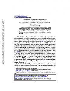
Fig. 16. Magnitude response of the overall filter corresponding to six cascaded third-order half-band IIR filters.
Fig. 17. Magnitude response (normalized) of the prototype filter in Example 3.
TABLE V IMPULSE RESPONSE OF THE PROTOTYPE FILTER AND MULTIPLIER COEFFICIENTS IN EXAMPLE 3
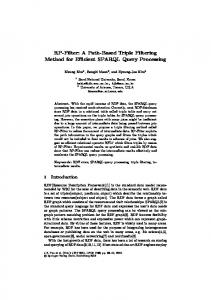
The stopband attenuation of this third-order filter, with a quantized coefficient, is then 11.126 dB. Using (40) and (41), the passband and stopband edges of the prototype FIR filter can then be computed as 32.26 and 147.74 , respectively. The specification for the passband ripple and stopband attenuation of the prototype filter is the same as for the overall filter, 0.2 and 60 dB, respectively. For this filter, we use a minimum-phase FIR filter, designed with the aid of the procedure in [12], [13]. The order of the FIR filter that meets the requirements is six. The impulse response values of this filter, and the interconnecting multiplier coefficients , are given in Table V. The magnitude responses of the prototype filter and of the overall filter are shown in Figs. 17 and 18, respectively. The coefficients, , are in this case not rational numbers and consequently, it is not possible to use the equivalence of Fig. 9 in order to obtain integer multipliers. The number of bits required to keep the stopband attenuation above 60 dB is 11 for these coefficients (8 fractional bits). For 11 bits, the passband ripple is only slightly increased from the realization using nonquantized coefficients (from 0.109 to 0.113 dB). The required number of adders becomes 41 in total. Compared with, for example, the realization where in Example 1 (which still meets the requirement of 0.2-dB passband ripple), this is an increase by 46%. On the other hand, the maximal sample frequency is 40% higher here. Hence, there is a tradeoff between the arithmetic complexity and the maximal sample frequency.
Fig. 18. Magnitude response (normalized) of the overall filter in Example 3.
Example 4: We consider design of a QMF bank using the new analysis—and synthesis filter bank structures in Fig. 12. is The specification for the low-pass filter, and dB. This filter is designed in the same manner as the overall filter in Example 3. Again, we use the third-order half-band filter with , which reduces the the coefficient quantized to . problem to designing a low-pass prototype FIR filter, The passband and stopband edges of the prototype filter are ), respectively, again 32.26 (0.179 ) and 147.74 ( whereas the stopband attenuation is the same as for the overall specification, 30 dB. Again we use the procedure in [12], [13] to design this filter, but with the restriction that be a valid half-band filter. A filter of order five will meet the requirements. The impulse response of this filter, and the multiplier coefficient, are given in Table VI. In column three the quantized values are tabulated. We see that the coefficients in this specific example are very simple and require at most 6 bits (3 fractional) for an attenuation of 30 dB. The magnitude responses of the
JOHANSSON AND WANHAMMAR: HIGH-SPEED RECURSIVE FILTER STRUCTURES COMPOSED OF IDENTICAL ALL-PASS SUBFILTERS
TABLE VI IMPULSE RESPONSE OF THE PROTOTYPE FILTER AND MULTIPLIER COEFFICIENTS IN EXAMPLE 4
27
This approach makes it possible to achieve a smaller passband ripple than for the cascade design. The design of the analysis and synthesis filters in the filter bank also reduces the design of a prototype FIR filter and a half-band IIR filter. One major advantage of the proposed structures over the corresponding conventional structures is that the coefficients of the all-pass filters is much shorter, implying that the maximal sample frequency is substantially higher for a given VLSI technology. Examples showed that, for interpolation and decimation filters, the arithmetic complexity may be lower as well, whereas for filter banks, the increase in speed is paid for by an increased arithmetic complexity. For interpolation and decimation, an alternative to increasing the speed is to use cascaded half-band filters straightforwardly. The examples revealed that the complexity is lower for the new structures than for these structures. An advantage of the new ones over these is the possibility of using a design for reduced passband ripple. Ongoing and future work is devoted to noise analysis and implementation issues for the proposed filter structures. REFERENCES
N
Fig. 19. Magnitude responses (normalized) of the power-complementary filters in Example 4.
power-complementary filters, and , are shown in Fig. 19. Using a conventional filter bank with half-band IIR filters, are met by a seventh-order Cauer the requirements on filter. For this filter, the required coefficient word length after rounding is 6 bits. With the same assumptions as earlier, the . Using the new maximal sample frequency becomes , an increase by 60%. filter bank structure the figure is However, the gain in speed is paid for by an increase in the number of arithmetic operations.; the number of additions is increased by approximately a factor of two. This is explained by the fact that the filters must be power complementary in order to obtain perfect magnitude reconstruction. For interpolation and decimation filters this is not necessary, which means that the FIR prototype filter can be of lower order in that context. V. CONCLUSION In this paper, we have introduced high-speed recursive filter structures for interpolation, decimation, and QMF banks with perfect magnitude reconstruction. The structures use identical all-pass subfilters and multipliers for interconnection of these subfilters. Given the overall transfer function, the multipliers can be computed using simple recurrence formulas. Two different design techniques for the interpolation and decimation filters were considered. In the first one, the overall transfer function corresponds to a number of half-band IIR filters in cascade. In the second one, the design is split into designs of a prototype FIR filter and a half-band IIR filter.
[1] M. Renfors and T. Saram¨aki, “Recursive th-band digital filters—Part I: Design and properties,” IEEE Trans. Circuits Syst., vol. CAS-34, pp. 24–39, Jan. 1987. [2] A. Fettweis and K. Meerk¨otter, “Suppression of parasitic oscillations in wave digital filters,” IEEE Trans. Circuits Syst., vol. CAS-22, pp. 239–246, Mar. 1975. [3] A. Fettweis, “Wave digital filters: Theory and practice,” Proc. IEEE, vol. 74, pp. 270–327, Feb. 1986. [4] W. Wegener, “Wave digital directional filters with reduced number of multipliers and adders,” Arch. Elektr. Ubertragung., vol. 33, pp. 239–243, June 1979. [5] L. Gazsi, “Explicit formulas for lattice wave digital filters,” IEEE Trans. Circuits Syst., vol. CAS-32, pp. 68–88, Jan. 1985. [6] M. Renfors and Y. Neuvo, “The maximum sampling rate of digital filters under hardware speed constraints,” IEEE Trans. Circuits Syst., vol. CAS-28, pp. 196–202, Mar. 1981. [7] L. Wanhammar, DSP Integrated Circuits. New York: Academic, 1998. [8] A. P. Chandrakasan and R. W. Brodersen, Low Power Digital CMOS Design. Norwell, MA: Kluwer, 1995. [9] T. Saram¨aki and M. Renfors, “A novel approach for the design of IIR filters as a tapped cascaded interconnection of identical allpass subfilters,” in IEEE Int. Symp. Circuits and Systems, Philadelphia, PA, May 4–7, 1987, vol. 2, pp. 629–632. [10] I. Kale, R. C. S. Morling, A. Krukowski, and C. W. Tsang, “A highfidelity decimator chip for the measurement of sigma-delta modulator performance,” IEEE Trans. Instrum. Meas., vol. 44, pp. 933–939, Oct. 1995. [11] J. H. McClellan, T. W. Parks, and L. R. Rabiner, “A computer program for designing optimum FIR linear phase digital filters,” IEEE Trans. Audio Electroacoust., vol. AU-21, pp. 506–526, Dec. 1973. [12] O. Herrman and H. W. Schussler, “Design of nonrecursive digital filters with minimum phase,” Electron. Lett., vol. 6, no. 11, pp. 329–330, May 1970. [13] S. K. Mitra and J. F. Kaiser, Handbook for Digital Signal Processing. New York: Wiley, 1993, ch. 4.9. [14] N. J. Fliege, Multirate Digital Signal Processing. New York: Wiley, 1994. [15] P. P. Vaidyanathan, “Passive cascaded lattice structures for low sensitivity FIR filter design, with applications to filter banks,” IEEE Trans. Circuits Syst., vol. CAS-33, pp. 1045–1064, Nov. 1986. [16] P. P. Vaidyanathan and P. Q. Hoang, “Lattice structures for optimal design and robust implementation of two-channel perfect-reconstruction QMF banks,” IEEE Trans. Acoust., Speech, Signal Processing, vol. 36, pp. 81–94, Jan. 1988. [17] P. P. Vaidyanathan, Multirate Systems and Filter Banks. Englewood Cliffs, NJ: Prentice-Hall, 1993. [18] P. A. Regalia, S. K. Mitra, and P. P. Vaidyanathan, “The digital all-pass filter: A versatile signal processing building block,” Proc. IEEE, vol. 76, pp. 19–37, Jan. 1988.
28
IEEE TRANSACTIONS ON CIRCUITS AND SYSTEMS—II: ANALOG AND DIGITAL SIGNAL PROCESSING, VOL. 46, NO. 1, JANUARY 1999
[19] M. J. T. Smith and T. P. Barnwell III, “A procedure for designing exact reconstruction filter banks for tree-structured subband coders,” in Proc. IEEE Int. Conf. Acoustics, Speech, and Signal Processing, San Diego, CA, Mar. 1984, vol. 2, pp. 2711–2714. [20] M. Vesterbacka, K. Palmkvist, and L. Wanhammar, “On implementation of fast, bit-serial loops,” in Midwest Symp. on Circuits and Systems, Ames, Iowa, Aug. 18–21, 1996, vol. 1, pp. 190–193. [21] A. G. Dempster and M. D. Macleod, “Use of minimum-adder multiplier blocks in FIR digital filters,” IEEE Trans. Circuits Syst. II, vol. 42, pp. 569–577, Sept. 1995. [22] M. Potkonjak, M. B. Srivastava, and A. P. Chandrakasan, “Multiple constant multiplications: Efficient and versatile framework and algorithms for exploring common subexpression elimination,” IEEE Trans. Computer-Aided Design, vol. 15, pp. 151–165, Feb. 1996. [23] I. Kunold, “Linear phase realization of wave digital filters,” in IEEE Int. Conf. on Acoustics, Speech, and Signal Processing, New York, 1988, vol. 3, pp. 1455–1458. [24] M. S. Anderson, S. Summerfield, and S. S. Lawson, “Realization of lattice wave digital filters using three-port adaptors,” Electron. Lett., vol. 31, no. 8, pp. 628–629, Apr. 1995.
H˚akan Johansson (S’98–M’99) was born in Kumla, Sweden, on July 1, 1969. He received the Civ.Ing. degree in 1995, the Tekn. Lic. degree in 1997, and the Tekn. Dr. degree in 1998, all from Link¨oping University, Sweden. Since 1995 he has been with the Division of Electronics Systems at the Department of Electrical Engineering, Link¨oping University. His research interests are mainly in the area of digital filters, with emphasis on realization and implementation issues. He is co-author of one textbook on digital filters, and is the author of more than a dozen papers.
Lars Wanhammar (S’74–M’81) was born in Vansbro, Sweden, on August 19, 1944. He received the Tekn. Mag. degree in 1970, the Civ.Ing. degree in 1980, the Tekn. Dr. degree in 1981, and the Docent degree in 1986, all from Link¨oping University, Sweden. He is currently Professor of Electronics Systems at the Department of Electrical Engineering, Link¨oping University. His research interests concern theory and design of digital signal processing systems, particularly digital filters and fast transforms, as well as computational properties of DSP algorithms, CAD tools, and VLSI circuit techniques. He has authored and co-authored seven textbooks.