Roger C. Reed, Kenneth A. Green, Pierre Caron, Timothy P. Gabb, Michael G. Fahrmann, Eric S. Huron and ..... Strusrud, R.A. MacKay, D.L. Anton, T. Khan, R.D..
Superalloys 2008 Roger C. Reed, Kenneth A. Green, Pierre Caron, Timothy P. Gabb, Michael G. Fahrmann, Eric S. Huron and Shiela A. Woodard TMS (The Minerals, Metals & Materials Society), 2008
HIGH TEMPERATURE NANOINDENTATION OF NI-BASE SUPERALLOYS A. Sawant1, S. Tin1 and J.-C. Zhao2 1
Illinois Institute of Technology, 10 W. 32nd St. Chicago IL 60616 The Ohio State University, 2041 College Rd., Columbus, OH, 43210
2
Keywords: high temperature indentation, superalloy, single crystal, diffusion multiple parameters and microstructure. For meaningful analyses of indentation data, knowledge of both the contact mechanics and underlying structure of the material is required to minimize the occurrence of experimental artifacts that may distort the resulting data. To complement indentation studies, computational modeling efforts are commonly employed to simulate the evolution of the plastic zone beneath the indenter and determine the effective stresses present within the material. Depending on the nature of the problem that is being addressed, different types of models can be applied to simulate the characteristic response of the material during indentation[9-15]. For example, atomistic, molecular dynamics (MD) and dislocation dynamics models are often used to quantify the initial events corresponding to plastic deformation and develop theories that elucidate the observed size effects during indentation. Continuum-based models, on the other hand, are often applied to develop qualitative engineering correlations between indentation properties and mechanical properties in bulk materials. Combining these models will serve to assist in bridging the gap between continuum and dislocation plasticity.
Abstract Novel techniques for characterizing and assessing the properties of Ni-base superalloys are becoming increasingly important to the accelerated development of new structural alloys and the advancement of physics-based mechanical property models. Instrumented indentation techniques have long served as a useful approach for probing the mechanical response of a wide range of engineering materials. Nano and micro-indentation techniques are particularly well suited for measuring the properties of materials and structures in which the size or volume of the sample would make conventional mechanical testing methods cumbersome or cost prohibitive. Deformation volumes can be carefully controlled such that indentation can be applied to probe the properties of specific phases or features present within the microstructure. Moreover, recent developments in micromachining of micropedestal specimens via focused ion milling, chemical etching or femtosecond laser ablation allow for the direct assessment of compressive stress-strain responses using indentation equipment. Since high temperature structural materials, such as Ni-base superalloys, are primarily used in a variety of critical applications for turbine engines, materials development and usage of life prediction models has traditionally been extremely conservative. Predictive physics-based deformation models may increase the confidence of the property values and minimize some of the design conservatism, thus allowing more efficient materials usage and contributing to more efficient engine operation. Such predictive models may also accelerate the development of high temperature structural materials with improved temperature capability to further enhance engine performance. Recent developments have led to the ability to conduct instrumented micro/nano-indentation at elevated temperatures. Utilization of high temperature indentation techniques may potentially address some of these challenges associated with understanding the fundamental deformation mechanisms across limited length scales as well as establish new methods of utilizing combinatorial techniques for the design of structural materials.
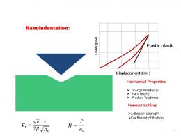
For low load micro- and nano- indentation, the area of contact between the indenter and material varies during testing and is indirectly measured using the depth of penetration. Unlike conventional hardness tests, the residual impression left on the surface of the material does not need to be measured as the uniform geometry of the indenter tip combined with precise displacement sensing equipment with nanometer resolution is used to calculate the contact area during indentation as a function of load. The resulting load-displacement curves are then used to quantify the hardness of the material, HIT, which is defined as the ratio of the maximum load, PMAX, over the projected area, AP. In addition to measuring the hardness, indentation techniques are also commonly used to determine the elastic modulus, fracture toughness, flow stress and strain hardening exponent of the material being tested. During indentation, the initial contact between the indenter and sample surface can be considered elastic. As the load increases, plastic flow and yielding occurs beneath the material in contact with the indenter. Once the maximum load is attained, the slope of the unloading curve measured from the tangent of PMAX can be analyzed to calculate the elastic modulus of the sample material. For viscoelastic materials, these analyses do not necessarily hold true as the linear relationship between load and penetration depth during unloading may be influenced by parameters, such as the loading/unloading rate as well as the magnitude of the maximum load. A distinguishing characteristic corresponding to viscoelastic materials is the tendency to continue to deform at a constant applied load. The resulting depth change as a function of time is often referred to as indentation creep, although the source of this displacement in certain instances may not be directly attributed to plastic flow. Growth of cracks originating from the indent may also serve to change the displacement of the indenter as a constant
Introduction Instrumented indentation has become an important tool that can be used to evaluate the mechanical properties of a wide range of engineering materials across the nano-, micro- and meso- length scales[1-4]. The simplicity of the indentation process offers a number of advantages when compared to other experimental approaches for assessing the micro-mechanical properties of materials and structures that possess limited volumes. By varying the indenter tip geometry and applied load, indentation techniques can be used to probe different volumes of material[5-8]. Interpretation of the resulting load-displacement curves, however, is non-trivial as the strain fields underneath the indenter tip are extremely complex and sensitive to material processing
863
load. In these instances, the growth of the cracks and fracture toughness of the material can be assessed from the steady state displacement rate when held at PMAX.
are highly sensitive to minor changes in temperature, a liquidcooled heat shield was inserted to isolate and contain the radiant heat emanating from the hot stage and indenter. The temperature of the MicroMaterials platform and ambient temperature of the environmental cabinet was maintained at 30°C ± 0.1°C during testing. Sharp diamond and sapphire Berkovich indenters were used to assess the hardness and modulus of the superalloy samples as a function of temperature up to 600°C. A heated diamond Berkovich indenter was used for the majority of tests conducted at temperatures below 500°C. Due to concerns with oxidation of the diamond tip at temperatures above 500°C, a heated sapphire indenter was used for all tests conducted above this temperature.
Instrumented indentation techniques are of great interest to scientists and engineers as it enables them to acquire mechanical property measurements from diverse classes of materials. The characteristic properties of biological materials and structures[16, 17] , organic polymers[18, 19], metals[20, 21], ceramics[22, 23] and electronic materials[24-26] can all be evaluated via indentation. Due to the ease of sample preparation and limited volume of deformed material, indentation tests are often considered to be nondestructive in nature. In addition to yielding direct information pertaining to the mechanical properties of the material, the characteristic shape of the resulting load-displacement curves can also be used to identify non-linear events occurring during indentation, such as pressure-induced phase transformations, coating or film delamination and defect nucleation. One of the fundamental limitations of many instrumented indentation systems is the lack of environmental control. The highly sensitive depth sensing systems that are utilized on most indentation systems requires a stable environment and temperature fluctuations of even a few degrees can influence both the compliance of the system and resolution of the control electronics. Since the systems are designed and calibrated specifically for operation at ambient conditions, the fidelity of the results acquired under non-ambient are typically unreliable. With many engineering structures and devices being utilized at non-ambient temperatures and conditions, the applicability of indentation techniques for these particular materials is limited due to the lack of temperature dependent mechanical properties.
Figure 1: MicroMaterials NanoTest system contained within an environmental enclosure. Indentation was performed on solution treated and aged single crystal CMSX-4 samples oriented along the and directions as well as a combinatorial diffusion multiple consisting of polycrystalline Ni-based superalloys: IN100, IN718, Rene 95 and ME3. Compositions of the alloys are listed in Table I. The diffusion multiple measured 25mm in length and consisted of a 25 mm diameter cylinder with a 14 x 14mm square opening into which four rectangular 7mm X 7mm X 25mm bars of the constituent alloys were inserted. All of the superalloy samples were sectioned using electro-discharge machining (EDM). The assembly was subjected to hot-isostatic pressing (HIP) cycle at 140MPa, 1150°C for 1000h followed by a water quench. Additional details of this process along with the assessment of the compositional gradients within the interdiffusion zone can be found in Ref [27]. Assembly of the combinatorial diffusion multiple yielded four pairs of diffusion couples: Rene 95 – IN718, Rene 95 – ME3, IN718 – IN100, ME3 – IN100. The finished sample was cut into slices approximately 5mm thick and prepared using standard metallographic techniques. To investigate the role of microstructure on the indentation response, the diffusion multiple was evaluated in the as quenched condition, as well after an 1100˚C exposure for eight hours followed by a furnace cool. The subsequent heat treatment and slow cool allowed the intragranular γ’ precipitates within the microstructure of the alloys to coarsen to sizes that are more representative to those found in commercially processed structures. A solution of 33%HCl, 33%HNO3 and 33%H2O was used to lightly etch the microstructure of the diffusion multiples and reveal the exact location of the interdiffusion zones. The load used during indentation was 200mN, while the loading and unloading rates were 3mN/s and 9mN/s accordingly. The dwell at maximum load varied between 30 and 1500s while
The present investigation has focused on evaluating the high temperature mechanical properties of Ni-base superalloys at elevated temperatures using these instrumented indentation techniques. The anisotropy of a commercial single crystal Nibase superalloy was assessed and used to derive a phenomenological model capable of accounting for the visoelastic effects present at elevated temperatures. Once the methodology for assessing and analyzing the high temperature load – displacement indentation curves was established, the technique was applied to evaluate the mechanical properties of a multicomponent diffusion couple. The interdiffusion zones of the diffusion multiple were probed to correlate variations in hardness and modulus with the graded composition. Experimental Materials and Procedure A MicroMaterials indentation platform shown in Figure 1 was used to conduct high temperature indentation studies. The platform is contained within an environmental chamber purged with high purity Ar such that O2 levels are maintained below 0.01% to minimize oxidation of both the sample surface as well as the indenter tip. Square specimens with edge lengths measuring ~10mm and a thickness of 3mm were mounted onto a refractory ceramic hot block. Resistance heaters located directly beneath the surface of the ceramic hot block were used to provide specimen heating. To minimize transient thermal fluctuations and heat transfer between the specimen surface and indenter tip during testing, a separate resistance heater and thermal control system was used to provide heating of the indenter. The temperatures of the specimen surface and indenter were controlled to within ~0.1°C. Since both the electronics and overall frame compliance
864
Table I: Nominal compositions of the alloys (wt.%) investigated
Alloy Rene95 IN718 IN100 ME3 CMSX-4
Ni 62.4 53.0 60.4 50.9 61.2
Al Co Cr Fe Mo 3.5 8.0 13.0 3.5 0.5 19.0 18.5 3.5 5.5 15.0 10.0 3.0 3.4 20.6 13.0 3.8 5.6 10.0 6.5 0.6
Nb 3.5 5.1 -
Ti 3.7 0.9 4.7 3.7 1.0
V 1.0 -
W Re Ta 3.5 2.1 - 2.4 6.0 3.0 6.0
resulting load-displacement curve[30-32]. A direct means of quantifying the creep compliance for a particular temperature, peak load (Pmax), and loading rate is to incorporate a constant load dwell during the nanoindentation test at Pmax. . The resulting depth change of the indenter as a function of time, dh , can then be used to calculate Ccreep. The creep dt compliance, dh , can be evaluated as follows: dP
the dwell to ascertain the thermal drift was set at 40s. Room temperature calibrations to assess system parameters and frame compliance were performed using standard fused silica, steel and elemental tungsten samples. Indentation tests were carried out at 30°C, 200°C, 300°C and 400°C. For the elevated temperature tests, a minimum of six discrete indentation measurements were evaluated at locations corresponding to nominally similar compositions.
C Creep =
High Temperature Indentation The standard methodology of applying an Oliver-Pharr powerlaw fit to the unloading portion of the load-displacement curve to evaluate the elastic modulus requires that the material being tested exhibit purely elastic behavior; this is a valid assumption for most metallic materials at room temperature.
h&creep dh dh 1 = . = dP dt dP P&creep dt
[3]
Ccreep can be effectively described as the rate of change of depth per rate of change of load. Since there is no change in load in the case of constant dwell at Pmax, the rate of change of load per time can be assumed to be proportional to the loading or unloading rate, dP . By applying this compliance correction,
−1
⎡1− ν 2 1− ν 2 ⎤ s in Er = ⎢ + ⎥ E E ⎣ s in ⎦
C B Zr 0.03 0.0015 0.03 0.08 0.16 0.14 0.06 0.05 0.025 0.05 -
dt
[1]
the elastic modulus of crystalline metallic materials can be accurately assessed as a function of temperature via nanoindentation.
Where Er is the reduced or nanoindentation modulus, Es is the modulus of the substrate, Ein is the modulus of the indenter, νs and νin are the Poisson’s ratio of the substrate and indenter, respectively. At elevated temperatures, however, the unloading response associated with many different classes of materials during indentation becomes visco-elastic in nature and the conventional analyses of the load-displacement curves are no longer valid. High temperature nanoindentation studies on materials such as fused silica[5] and bulk metallic glasses[29] have demonstrated the viability the testing technique, but many of the materials investigated exhibit minimal creep rates over the range of temperatures investigated. Polymeric materials, on the other hand, tend to exhibit complex visco-elastic-plastic responses[19] when tested at room temperature and multiple phenomenological approaches[18, 28] have been developed to effectively model their behavior and extract useful information from nanoindentation tests on these materials. One of the more common approaches to account for the time dependent deformation in crystalline metallic materials is the utilization of a straightforward two-element Maxwell model[29, 30]. In the approach, the creep-compliance, Ccreep, of the specimen is used to derive an equivalent expression for the change in contact stiffness measured during nanoindentation. Capparent = Celastic + Ccreep [2]
Results and Discussion Depending on the test temperature, dwell time and maximum load, the residual indents from the Berkovich tip appeared as an equilateral triangle with edge lengths measuring between 5µm and 10µm. The underlying microstructure of the solution heat treated and aged single crystal CMSX-4 contained a relatively uniform dispersion of cuboidal γ’ precipitates possessing edge lengths on the order of 500nm, while the microstructure of the sub-solvus processed polycrystalline alloys used to form the diffusion multiple typically contained a tri-modal distribution of γ’ precipitates. For the single crystal CMSX-4 sample, the comparatively homogeneous microstructure enabled sufficiently large volumes of both the γ and γ’ phases to be deformed during indentation and the resulting modulus measurements are representative of the bulk. For the constituent alloys comprising the diffusion multiple, however, the heterogeneity of the γ’ microstructure coupled with the random grain orientation prohibited direct correlation of indentation hardness and modulus with the bulk alloy properties at low loads (