High throughput integration of optoelectronics devices for biochip fluorescent detection Evan Thrush*a, Ofer Levia, Ke Wanga, James S. Harris Jr.a and Stephen J. Smithb a Solid State and Photonics Laboratory, Stanford University b Dept. of Molecular and Cellular Physiology, Stanford University ABSTRACT Miniaturized, portable and robust sensing systems are required for the development of integrated biological analysis systems and their application to clinical diagnostics. This work uses vertical cavity surface emitting lasers (VCSELs), optical emission filters and PIN photodetectors to realize monolithically integrated, near infrared, fluorescence detection systems. The integration of these micro technologies with biochip applications will drastically reduce cost and allow for parallel sensing architectures, which is particularly useful for flow channel arrays such as in capillary array electrophoresis. This paper focuses on the fabrication of integrated fluorescence sensors. Fabrication procedures have been developed to realize intracavity contacted VCSELs and low noise photodetectors, such as selective AlGaAs wet etching and via planarization. A reflow process with positive photoresist has been developed to provide via electrical contacts and to optically isolate the photodetector from the light source. Three-dimensional microstructures can be simply made by this reflow technique. Optical simulations predict that a detection sensitivity lower than 10000 molecules per 104µm2 sample area. Single molecule detection may be possible in certain sensing architectures. Keywords: Biochips, fluorescence, sensors, infrared dyes, VCSELs, semiconductor lasers, photodetectors, fabrication
1. INTRODUCTION The integration and scaling of biological analysis systems will find wide applicability in the areas of bio-warfare, clinical medicine and biological experimentation. Medical diagnostics still rely upon labor intensive, timely, and expensive laboratory techniques. The experience of waiting for days or even weeks for the results of a test for infectious disease is a common reality of modern day medical practice. Small portable micro-total analysis systems (µTAS) promise to provide immediate point of care services that would facilitate detection of cancer, disease and bio-warfare agents1,2. Moreover, integrated biological analysis systems will provide high throughput experimentation and give scientists a better understanding of complex biological processes. This will naturally lead to the discovery of innovative drugs and medical treatments. A variety of sensing schemes have been developed for molecular detection, such as electrochemical, optical absorption, and interferometric sensing3,4,5. However, fluorescence sensing remains the most widely used methodology in biotechnology. Separation technologies, such as capillary array electrophoresis and micro-array technology use fluorescent labeling for the detection of DNA and proteins. Fluorescence detection offers exquisite sensitivity, specificity and compatibility with standard biochemical reactions, such as polymerase chain reaction (PCR). Traditional bio-fluorescence readers use bulky and discrete elements, which are expensive and require large footprint and precise alignment. The advantages of integrated biological analysis systems are reduced when these systems rely upon large and fragile optical sensing equipment. Integrated on-chip sensing architectures make portable and robust medical care equipment practical. As a result of the recent explosion in optoelectronics for telecommunications, a variety of interesting and useful integrated optical sensing architectures can now be realized6,7,8,9. The theme of our research is exploring sensing architectures that hold potential to be inexpensive, parallel, and micro-scale solutions 10. This paper presents progress towards the monolithic integration of vertical cavity surface emitting lasers (VCSELs), PIN photodetectors and emission filters to achieve fluorescence sensing.
162
Microfluidics, BioMEMS, and Medical Microsystems, Holger Becker, Peter Woias, Editors, Proceedings of SPIE Vol. 4982 (2003) © 2003 SPIE · 0277/286X/03/$15.00
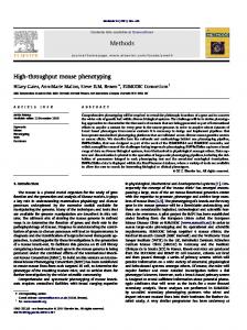
2. OPTOELECTRONIC DESIGN In regards to the overall system design, current work is being directed to filter through the many possible design alternatives to find the most optimal and practical solutions. Fig. 1 illustrates some general sensor architectures that are possible with vertical oriented optical devices, such as VCSELs, PIN photodiodes and emission filters. The imaging architecture utilizes micro-optics, refractive or diffractive, for focusing the laser beam and collecting the fluorescence. The proximity sensor allows the laser beam to propagate freely to the biological sample, and a large area detector, which surrounds the VCSEL, collects fluorescence. The waveguide architecture utilizes gratings to couple the laser beam into the waveguide, where the evanescent tail of the waveguide mode excites the biological sample. Then, the fluorescence is collected by the waveguide and coupled out onto the detector.
Figure 1: Schematics of system architectures: A) imaging, B) proximity and C) waveguide.
Achieving lasing, photo-detection and filtration from one GaAs substrate in a practical and inexpensive way is a design challenge. We propose a device design that utilizes existing VCSEL technology. Fig. 2 shows a schematic of the optoelectronic design. The VCSEL on the left includes two mirrors or distributed Bragg reflectors (DBRs) and a laser gain region. Adjacent to the VCSEL, a simple PIN photodetector is realized by adding an intrinsic GaAs region underneath the standard VCSEL epitaxial structure. The PIN photodetector utilizes the N-doped DBR as both an emission filter and electrical contact. The filtering behavior of the DBR is illustrated in Fig. 3. The DBR is highly reflecting at the lasing wavelength of 780nm (R > 99.999%) and relatively transparent at the Stokes’ shifted dye emission. It is important to note that this design achieves a high quality photodetector and emission filter by one simple modification to a typical VCSEL design. This will result in reduced costs and higher yield when compared to other integration schemes.
Proc. of SPIE Vol. 4982
163
Figure 2: Optoelectronic device design. A VCSEL, PIN photodetector and emission filter are monolithically integrated.
DBR Filter, Emission and Absorption Charactierstics 1.2
Emission Arbitrary Units
1
Absorption Reflectivity
0.8 0.6 0.4 0.2 0 750
775
800
825
850
875
Wavelength (nm)
Figure 3: Spectral characteristics of DBR filter and near-infrared fluorescent dyes.
4. FABRICATION There are some unique fabrication challenges associated with realizing monolithically integrated florescence sensors. The past year has been dedicated to overcoming these challenges and developing robust processes. The following section will cover in detail the fabrication procedures used to realize these sensors and increase sensor sensitivity. Fig. 4 shows SEM images of processed proximity sensors. The laser is located in the center of the annular shaped photodetector. Two interconnect lines can be seen making contact to the VCSEL structure in the center of the photodetector. Two electrical contacts or vias are made to the VCSEL and one via is made to the photodetector. The substrate is the other electrical contact for the photodetector. Cured photoresist formations and metal optical blocking layers can also be seen in the images.
164
Proc. of SPIE Vol. 4982
Figure 4a: SEM image of proximity sensor: VCSEL located in center of photodetector.
Figure 4b: Close up image of VCSEL structure, vias and metal optical block.
To give the reader a better understanding of the processing sequence to fabricate the proximity sensors, Fig. 5 can be used as an aid. The process begins with liftoff lithography for the top VCSEL ring contact. A bilayer liftoff process is used to yield an undercut profile, which is ideal for masking the metal contacts 11. Achieving an undercut profile is essential for being able to liftoff the center of the contact rings. E-beam evaporation is used to deposit Ti/Pt/Au for contact to the P-DBR. The next lithography step is used to mask the top mesa etch of the VCSEL. Standard positive photoresist is used to cover the center of the top ring contact while the outside of the metal ring masks the dry etch and defines the top mesa dimensions i.e. a self aligning process.
Figure 5: General processing sequence for sensor fabrication.
Proc. of SPIE Vol. 4982
165
For VCSELs and other thermally sensitive optoelectronics devices, it is important to use a GaAs contact layer to minimize contact resistance. Unfortunately, GaAs is absorbing at 780nm so this layer must be kept to a minimal thickness to maintain the cavity quality factor in 780nm intracavity contacted VCSELs. Researchers utilize a 10-20nm GaAs intracavity contact layer in 780nm VCSEL structures12. Contacting to such a thin layer is a challenge and selective etches are the logical choice to control the etch depth. The general methodology to control the etch depth is to dry etch into the cavity of the VCSEL and, then, perform selective wet etching to land on the thin 10nm GaAs layer. An ECR-RIE plasma etch is used to etch into the lambda cavity of the VCSEL. Precise control of the etch depth is important because selective wet etches are used in the subsequent step to etch onto the thin GaAs intracavity contact layer. An optical monitor is used to control the etch depth precisely. Better than 30nm etch resolution is possible with the optical etch monitor13. In fact, the limiting parameter during dry etching is the etch non-uniformity across the wafer piece due to the uneven electrical and thermal contact to the carrier wafer. By etching into the cavity of the VCSEL, this non-uniformity problem is alleviated to some extent because the cavity length is usually greater than the etch nonuniformities.
Figure 6: Selective wet etch processing sequence.
Having dry etched into the cavity of the VCSEL, a series of selective etches are used to land on the thin 10nm GaAs intracavity contact layer (Fig. 6). First, a citric acid:H202 (12:1) etch for 2 min. is used to remove the rest of the VCSEL cavity (Al.3Ga.7As) and land on the oxide aperture layer (Al.98Ga.02As)14. A buffered oxide etch (BOE):DI water (1:15) etch for 30 seconds is used to remove the oxide aperture layer and stop on the 10nm GaAs layer14. Then, a digital etch that alternates between ammonium hydroxide:DI water (1:10) and hydrogen peroxide is used to clean the surface. Usually, one cycle of digital etching is enough to clean the surface. These etches work well in that they provide good etch selectivity and provide minimal undercutting of the mesa structures. We find that HCl based selective etches drastically undercut mesa structures and is difficult to control15. The next series of processing steps are used to form the bottom mesa of the VCSEL and detector mesa. The intracavity and photodetector contacts are defined in the same liftoff process. E-beam evaporation is used to deposit Au/Ge/Ni/Au for the n contact. Then, typical lithography is used to mask the bottom mesa etch. Again, the bottom mesas are etched by ECR-RIE plasma etching. This dry etching step exposes the active perimeter of the photodetector. Photodetector dark current becomes highly dependent on subsequent processing steps. To maintain low dark current, it is best to avoid high temperature procedures and oxygen descuming plasmas. Therefore, contact annealing and wet oxidation of the VCSEL current aperture are conducted before the bottom mesa etch. We find that it is possible to achieve dark currents as low as 500fA/mm detector diameter10. For high sensitivity applications, it is important to maintain a low detector dark current. However, one can reduce dark current noise by operating at 0V detector bias where the dark current is negligible. The photodetector response is virtually bias independent, which is to be expected for low speed and low power operations. Fig. 7a shows the photodetector response for a variety of applied biases. The difference in the response can be attributed to the increase in dark current with detector bias. Also, Fig. 7b shows the dark current of a
166
Proc. of SPIE Vol. 4982
photodetector at 0V applied bias. The dark current of the photodetector shown in Fig. 7b at 5V is in the nA range. By operating at 0V, the detector dark current has been greatly reduced.
Dark Current at 0V 180
0.34
160 Photocurrent (fA)
Photocurrent (nA)
Detector Sensitivity to Bias Condition 0.35
0.33 0.32
0V
0.31
2.5V 5V
0.3 0.29
140 120 100 80
0.28
60
0
1
2
3
4
5 6 Time (s)
7
8
9
10
Figure 7a: Photodetector response for a variety of applied biases.
0
2
4
Time (s)
6
8
10
Figure. 7b: Detector dark current at 0V applied bias.
The next processing step involves making electrical contacts or vias to the optoelectronic ring contacts and developing blocking walls for optical isolation purposes. Researchers show that cured positive photoresist can provide threedimensional microstructures for such purposes16,17,18. We use a positive photoresist provided by Clariant called AZ9260. The processing involves simple lithography and a 2 hour cure at 250C. Curing the photoresist reflows the photoresist and provides gradual sloping contours, which are excellent for forming vias. Also, the cured resist proves to be extremely resistant to solvents and electrically insulating. Another advantage of using positive photoresist is the high aspect ratios that are easily achievable in thick films (10-20µm), giving increased processing control. Utilizing the cured photoresist for optical blocking structures will increase sensor sensitivity. A significant amount of spontaneous emission is emitted from the side of the VCSEL, even when the VCSEL lazes. During lazing operation, it is quite possible to have a 1mW LED that emits in all 4π steradians of space. A significant fraction of this light will be incident on the photodetector. We are hoping to reduce the laser background to less than 1pW. Therefore, significant filtration is needed to achieve exquisite sensitivities. The filter located on top of the detector will not filter the light emitted directly from the side of the VCSEL because the filter operates for vertically propagating light. Clearly, some type of optical block is needed.
Figure 8a: Illustration of VCSEL and photodetector crosstalk.
Figure 8b: Illustration of optical block to prevent crosstalk
Proc. of SPIE Vol. 4982
167
To provide an optical block, the detector sidewall is coated with cured positive photoresist and, then, metal is deposited on the detector sidewall. The metal will reflect incident radiation from the VCSEL side. The cured positive photoresist provides a microstructure to support the metal and prevents the detector junction from being electrically shorted. One can imagine other types of optical blocks. Future sensor designs will use an absorbing medium instead of a metallic interface to optically isolate the photodetector from the VCSEL. A black polyimide (DARK 300), made by Brewer Science, will be investigated as a possible absorbing medium for optical isolation. The cured resist microstructures for vias and optical blocking are made during the same lithography and curing step. The same liftoff procedure is used to metalize the via and optical blocking formations. In comparison to the previous metalizations, the liftoff procedure is slightly modified. A bilayer liftoff process is used again; however, a thicker 8um top layer film is used in the bilayer scheme. This proves to be important in liftoff masking over tall (13µm) and highly three-dimensional microstructures. E beam evaporation is used to deposit Ti/Au for via and optical blocking metalization.
5. OPTICAL SIMULATIONS The optoelectronics described in the above sections can be utilized in a staggering number of system architectures. This fact in conjunction with the many design tradeoffs and parameters needed to be considered has inspired our use of computer modeling to find optimal system designs. A ray-tracing program called ASAP from BRO (Tucson, Arizona) is being used to perform the optical simulations. If one neglects laser background, previous simulations have shown that detection of less than 5000 molecules should be possible with the proximity architecture10. Since laser background will most likely limit sensor sensitivity, future optical simulations will focus on predicting the amount of laser background detected by the photodetector. There should be three sources of laser background: cross talk as seen in Fig. 8, direct specular reflection and scattering from optical interfaces. Accurate scattering and optical models will need to be developed to properly predict sensor performance. Fig. 9 gives the reader a flavor of the type of simulations used to predict laser background from crosstalk. Fig. 9a shows the VCSEL structure modeled in ASAP. The VCSEL active layer is modeled as an LED emitting in all 4pi steradians of space. Some spontaneous emission escapes from the VCSEL side. Fig. 9b shows the ray traces within the VCSEL structure. We hope that simulations like these will accurately predict the amount of laser background at the photodetector.
Figure 9a: Simulating spontaneous emission emitted from from VCSEL side.
Figure 9b: Simulation of spontaneous emission within VCSEL structure
5. CONCLUSIONS Fabrication processes have been developed that will enable the integration of photodetectors, VCSELs and emission filters. Cured positive photoresist is an excellent material for making useful microstructures such as vias and optical blocking walls. Optical blocking layers will prove vital in lowering laser background and achieving high sensitivities.
168
Proc. of SPIE Vol. 4982
Integration of a VCSEL, photodiode and optical emission filter on one GaAs substrate enables simple and easy integration of fluorescence detection systems. The potential applications of such a sensor are numerous, ranging from µTAS systems to micro-array readers.
ACKNOWLEDGEMENTS We would like to acknowledge the Defense Advanced Research Project Agency (DARPA) as the primary funding agency for this project. Also, the National Science Foundation is supporting this work through a Graduate Research Fellowship. We would like to thank Breault Research Organization (BRO) from Tucson, AZ for licensing ASAP to us for educational purposes. REFERENCES 1. 2.
3. 4. 5. 6. 7. 8. 9. 10. 11. 12. 13.
14. 15. 16. 17.
18.
A. Manz, N. Graber, and H. M. Widmer, "Miniaturized total chemical-analysis systems: a novel concept for chemical sensing," Sensors and Actuators B, pp. 244-248, 1990. K. E. Petersen, W. A. McMillan, G. T. A. Kovacs, M. A. Northrup, L. A. Christel, and F. Pourahmadi, "Toward next generation clinical diagnostic instruments: scaling and new processing paradigms," Journal of Biomedical Microdevices, 1(1), pp. 71-79, 1998. R. E. Kunz, "Miniature integrated optical modules for chemical and biochemical sensing," Sensors and Actuators B, 38-39, pp. 13-28, 1997. E. Verpoorte, A. Manz, H. Ludi, A. E Bruno, F. Maystre, B. Krattiger, H. M. Widmer, B. H. van der Schoot, and N. F. de Rooij, "A silicon flow cell for optical-detection in miniaturized total chemcial-analysis systems," Sensors and Actuators B, 66(6), pp. 66-70, 1992. A. T. Woolley, K. Lao, A. Glazer, and R. A. Mathies, "Capillary electrophoresis chips with integrated electrochemical detection," Anal.Chem., 70, pp. 684-688, 1998. M. T. Gale, R. E. Kunz, and H. P. Zappe, "Polymer and III-V transducer platforms for integrated optical sensors," Optical Engineering, 34(8), pp. 2396-2406, 1995. J. C. Roulet, R. Volkel, H. P. Herzig, E. Verpoorte, N. F. de Rooij, and R. Dandliker, "Microlens systems for fluorescence detection in chemical microsystems," Optical Engineering, 40(5), pp. 814-821, 2001. M. Wiki and R. E. Kunz, "Wavelength-interrogated optical sensor for biochemical applications," Optics Letters, 25(7), pp. 463465, 2000. G. M. Yee, N. I. Maluf, P. A. Hing, M. Albin, and G. T. A. Kovacs, "Miniature spectrometers for biochemical analysis," Sensors and Actuators A, 58, pp. 61-66, 1997. E. Thrush, O. Levi, K. Wang, M. A. Wistey, J. S. Harris Jr., and S. J. Smith, "Integrated semiconductor fluorescent detection system for biochip and biomedical applications," SPIE Photonics West, vol. 4626, San Jose CA, 2002. R. Williams. Modern GaAs Processing Methods. Artech House, Boston MA, 1990. J. A. Lott and H. K. Shin, "Red and deep red vertical cavity surface emitting lasers with top and bottom AlGaAs/Al-oxide distributed bragg reflectors and AlGa-oxide current aperatures," 23rd International Symposium on Compound Semiconductors, St.Petersburg, Russia, pp. 377-380, 1996. G. A. Vawter, J. F. Klem, and R. E. Leibenguth, "Improved epitaxial layer design for real-time monitoring of dry etching in III-V compound heterostructures with depth accuracy of 8nm," Journal of Vacuum Science & Technology A, 12(4), pp. 1973-1977, 1994. J. H. Kim, D. H. Lim, and G. M Yang, "Selective etching of AlGaAs/GaAs structures using the solutions of citric acid H2O2 and de-ionized H2O buffered oxide etch," Journal of Vacuum Science & Technology B, 16(2), pp. 558-560, 1998. K. Bacher and J. S. Harris Jr., "A wet etching technique for accurate etching of GaAs/AlAs distributed bragg reflectors," Journal of Electrochemical Society, 142(7), pp. 2386-2388, 1995. K. M. Geib, K. D. Choquette, D. Serkland, A. A. Allerman, and T. W. Hargett, "Fabrication and performance of large (64x64) arrays of integrated VCSELs and detectors," SPIE Photoics West, 4649, 2002. G. A. Porkolab, S. H. Hsu, J. Y. Hryniewicz, W. H. Lim, T. J. Chen, S. Agarwala, F. G. Johnson, O. King, M. Dagenais and D. R. Stone, "Etch-mask of pyrolytic-photoresist thin-film for self-aligned fabrication of smooth and deep faceted three-dimensional microstructures," Journal of Vacuum Science & Technology B, 16(6), pp. 3650-3653, 1996. G. A. Porkolab, Y. J. Chen, S. A. Tabatabaei, S. Agarwala, F. G. Johnson, O. King O., M. Dagenais, R. E. Frizzel, W. T. Beard Jr. and D.R. Stone, "Air-bridges, air-ramps, planarization, and encapsulation using pyrolytic photoresist in the fabrication of three-dimensional microstructures," Journal of Vacuum Science & Technology B, 15(6), pp. 1961-1965, 1997.
*
[email protected]; phone 1-650-725-2774; fax 1-650-723-4659; http://snow.stanford.edu/~ethrush/; Stanford University, 420 Via Ortega, Stanford, CA, USA 94305
Proc. of SPIE Vol. 4982
169