3706
JOURNAL OF LIGHTWAVE TECHNOLOGY, VOL. 35, NO. 17, SEPTEMBER 1, 2017
Highly Sensitive Temperature Sensing Probe Based on Deviation S-Shaped Microfiber Jin Li, Qin Nie, Liting Gai, Hanyang Li, and Haifeng Hu
Abstract—Adeviation S-shaped microfiber was proposed and packaged in a capillary by glycerin solution. The high-temperature sensitivity performance was experimentally demonstrated. With the decrease in ambient temperature from 73.05 °C to 23.46 °C, the resonant dip on the transmission spectra red-shifts continually due to the co-operation between the refractive index increase of glycerol and the thermal expansion of packaging materials. The high sensitivity of ∼11 nm/°C promises high-sensitive monitoring of the slight temperature fluctuation in some specific biological and chemical reaction process Index Terms—Fiber sensors, integrated optics devices, temperature sensors.
I. INTRODUCTION IBER temperature sensors with excellent performances have been playing an important role and attracted great interest in the fields of biochemistry and industrial production in recent years [1]–[3]. These sensors usually operate on four typical mechanisms: distributed detection, fluorescence probe, fiber grating, and fiber interferometer [4]–[7]. Fiber interferometer based temperature sensor has the advantages of high resolution, wide dynamic response, and flexible structure [8], [9]. The M-Z interferometer temperature sensor can be constructed by cascading two single-mode fiber (SMF) cones together. For an interference length of 7.5 mm, the temperature sensitivity was obtained as 70 pm/°C [10]. By excitation of higher-order mode in photonic crystal fiber (PCF), a sensitivity of 31.8 pm/°C has been revealed [11]. The Michelson interferometer temperature sensor based on a peanut fiber structure has been demonstrated
F
Manuscript received March 7, 2017; revised May 24, 2017 and June 6, 2017; accepted June 16, 2017. Date of publication June 19, 2017; date of current version July 11, 2017. This work was supported in part by the National Natural Science Foundation of China under Grants 61405032, 61403074, and 61605031, in part by the Doctoral Scientific Research Startup Foundation of Liaoning Province (201501144), and in part by the Fundamental Research Funds for the Central Universities (N150404022, N150401001). The work of J. Li was supported by the China Scholarship Council for his Visiting Scholarship No. 201606085023. (Corresponding author: Jin Li.) J. Li is with the College of Information Science and Engineering, Northeastern University, Shenyang 110819, China, and also with the Laser Physics Centre, Australian National University, Canberra, A.C.T. 2601, Australia (e-mail:
[email protected]). Q. Nie, L. Gai, and H. Hu are with the College of Information Science and Engineering, Northeastern University, Shenyang 110819, China (e-mail:
[email protected];
[email protected];
[email protected]). H. Li is with the Key Lab of In-fiber Integrated Optics, Ministry Education of China, Harbin Engineering University, Harbin 150080, China (e-mail:
[email protected]). Color versions of one or more of the figures in this paper are available online at http://ieeexplore.ieee.org. Digital Object Identifier 10.1109/JLT.2017.2717485
with a sensitivity of 96 pm/°C [12]. For the F-P interferometer based temperature sensor, the highest sensitivity of 8.11 pm/°C has been reported [13]. Being limited by the thermal optical coefficient and thermal expansion coefficient of materials, the sensitivities of the temperature sensors mentioned above are relatively low. Liquid packaging method has been demonstrated to improve the sensitivity in recent years. By injecting ethanol into the micropores of the PCF connected in an optical-fiber loop mirror structure, a high sensitivity of 6.6 nm/°C was obtained [14]. However, in addition to the intrinsic temperature insensitivity of PCF, the high cost would be a serious problem for commercial application. Furthermore, the insert loss was serious for the splicing between normal SMF and PCF. Because of its simple structure and easy fabrication, SMF taper has been widely used in exploring some novel microstructural fiber sensors. Tian et al. reported the M-Z interferometer by cascading two SMF tapers [15]. The fiber taper with a length of 707 μm and a diameter of 40 μm was directly drawn by an ordinary optical-fiber fusion splicer, where the reference arm was encircled by the sensing arm and became independent of the environment. The effective refractive index of cladding mode (also named the sensing arm) was easily influenced by the environment. Therefore, the device became more stable and reliable. In 2014, Yang et al. prepared the S-shaped fiber taper by drawing SMF and studied its sensing characteristics. Experimental results indicated that the refractive index sensitivity was two orders higher than that of normal fiber interferometer sensor, and when compared with that of long-period fiber grating. After being packaged in a capillary, the temperature sensitivity was up to 1.4 nm/°C [16]. However, the effective sensing region was limited in the above structure, where the signal light cannot fully sense the environment temperature before being reflected into the fiber core. In this paper, a temperature sensor based on deviation S-shaped microfiber (DS-MF) interferometer has been experimentally demonstrated. For the deviation distance of 3 μm, the taper diameter of 55 μm, the deviation distance of 50 μm, and the cascade spacing of 2 cm, the temperature sensitivity of ∼11 nm/°C was demonstrated (the resolution is less than 10-3 °C). II. SIMULATION AND DESIGN To optimize the structure parameters, the physical model of a DS-MF interferometer was designed and studied by Rsoft. The physical model is shown in Fig. 1(a). In this structure, a deviation joint is introduced to divide the light and effectively
0733-8724 © 2017 IEEE. Personal use is permitted, but republication/redistribution requires IEEE permission. See http://www.ieee.org/publications standards/publications/rights/index.html for more information.
LI et al.: HIGHLY SENSITIVE TEMPERATURE SENSING PROBE BASED ON DEVIATION S-SHAPED MICROFIBER
3707
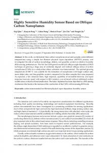
Fig. 2. Transmission spectra of DS-MF with different S-shaped lengths D (1 cm, 2 cm, 3 cm, 4 cm).
Fig. 1. (a) Physical model and (b) light field distribution of DS-MF in Rsoft. (c) Impact of deviation values Ds (blue dots-solid line) and Dd (Red cubesdashed line) on splitting ratio of transmission light.
enhance the sensing length of the S-shaped structure. When the light transmits through the structure, it can be effectively divided at both the deviation joint and S-shaped structure, as shown in Fig. 1(b). The DS-MF acted as a typical M-Z fiber interferometer. The phase difference Δϕ between core mode and cladding mode is shown as: 2πΔneff (Leff + Deff ) (1) λ Where, Δneff refers to the effective refractive index difference between fiber core and cladding, which were used as reference and signal arms, respectively; the sum of Leff + Deff stands for the effective length difference between the two arms of the M-Z interferometer; λ is the incident wavelength. The free spectra range (FSR) depends on the length (D) of the S-shaped structure, as illustrated in Fig. 2. When the length D changes from 1 cm to 4 cm with a step of 1 cm, the FSR would reduce from ∼40 nm to ∼10 nm. The extinction ratio would become worse as the length decreases. In this paper, the S-shaped structure with the length of 1 cm was chosen in the experiment to promise an adequate detection range and good extinction ratio. The refractive index sensing properties have been demonstrated by the simulation model. When the refractive index of the environment around DS-MF structure changed from 1.33 to 1.37 with a step of 0.01, the corresponding transmission spectra were calculated, as shown in Fig. 3(a). It was presented that the transmission dip drifted from ∼1.529 μm to ∼1.567 μm. The corresponding sensing characteristics curve was illustrated in Fig. 3(b), where the refractive index sensitivity of 960 nm/RIU was obtained with good linearity. During the sensor design Δϕ =
Fig. 3. Refractive index sensing properties of DS-MF. (a) Transmission spectra and (b) sensing characteristics curve for refractive index ranges from 1.33 to 1.37.
process, we should always balance between a high sensitivity and a wide detection range, since the transmission dip will overlap together beyond one FSR period and cannot be distinguished from each other. However, the multidips in the interference spectrum will shift to one direction as a whole. For the monotonously changing parameters, it is possible to continuously monitor the change by tracing a different dip in a different wavelength range when the two dips overlap in the former wavelength range. In this way, we should only pay attention to the relative wavelength shift. III. PREPARATION AND EXPERIMENTAL METHOD The temperature-sensing characteristics of DS-MF were demonstrated with the water immersion method. The
3708
JOURNAL OF LIGHTWAVE TECHNOLOGY, VOL. 35, NO. 17, SEPTEMBER 1, 2017
Fig. 4. (a) Experimental schematic of temperature sensor based on DS-MF micrograph of (b) deviation fiber and, (c) S-shaped microfiber taper, (d) image of packaged temperature sensor.
corresponding experimental schematic is illustrated in Fig. 4(a). The incident light was supplied by an ASE source with a wide spectrum ranging from 1520 nm to 1560 nm. The DS-MF was immersed in a water container. A thermal couple was used to monitor and record the temperature change. An OSA with the detection range of 1200–2000 nm and resolution of 20 nm was used to collect the transmission spectra. Inset shows the structure of DS-MF encapsulated by a capillary tube, which was filled with glycerin and plugged by epoxy resin (AB glue) on both sides. According to the M-Z sensing mechanism, the high sensitivity of this temperature sensor is caused by the reduction of neff due to the following two reasons: Δneff = Δneff (TOC) + Δneff (TEC)
(2)
The thermal optical coefficients (TOC) of silica and glycerin-water solution are Osilica = ∼ 1.0 × 10⁻⁵ /◦ C [17] and Oglycerin−water = ∼ −1.0 × 10⁻⁴ /◦ C [16], respectively. The TOC difference between silica and filled liquid will decrease the neff when the temperature increases and cause the blueshift of transmission spectra. Here, Δneff (TEC) = Δn(Esilica (T )) + Δn(EAB−glue (T )) + Δn(Eglycerol−water (T ))
(3)
Esilica (T ) = 0.55 ∼ 0.75 × 10⁻⁶ /◦ C [18], EAB−glue (T ) = 0.88 × 10⁻⁶ /◦ C [19], and Eglycerol−water (T ) = 1.33 × 10⁻⁴ /◦ C [20] are the thermal expansion coefficients (TEC) of silica, AB glue and glycerol-water, respectively, which also contribute to the neff decrease and the spectra blueshift for higher temperature [16]. The preparation process of deviation fiber structure is relatively simpler when compared with that of S-shaped fiber taper. The deviation value was manipulated by changing the axial offset of two electrical discharging probes of fiber-welding machine. The deviation value used in the experiment was 3 μm, the corresponding micrograph of deviation joint is shown in Fig. 4(b). The S-shaped microfiber taper was fabricated by heating and drawing the SMF in a fiber-welding machine, whose
electrical discharging probes were deviated similar to the preparation process of deviation structure. The length of the taper region was measured as 360.12 μm under the microscope. The distance between the deviation joint and the center of S-shaped microfiber taper was ∼2 cm. Fig. 4(c) indicates the micrograph of one S-shaped microfiber taper with the waist diameter of 55 μm and the S-shaped length of 50 μm. The waist diameter could be adjusted by multi-discharges, discharging intensity, as well as the indent and back distance of fiber holder in the Zaxis. The unpackaged DS-MF was fragile and hard to preserve or reuse. The photo of one packaged DS-MF was revealed in Fig. 4(d) (compared with a coin), whose diameter and length were ∼2 mm and ∼20 mm, respectively. The DS-MF structure was placed in a capillary tube, in which the glycerol solution with the concentration of 80% (refractive index of 1.4512 at room temperature) was filled. Then, the epoxy resin was used to encapsulate at the two ends of the capillary tube. The package not only supplied a more stable structure but also increased the temperature sensitivity due to the thermo-optic effect of glycerol solution and the thermal expansion of packaging materials. The high-temperature sensitivity can be attributed to the following reasons: first, the negative thermo-optic coefficient of glycerol solution resulted in the decrease of refractive index and the blueshift of resonant dip when the temperature raised; second, the resonant dip also blue-shifted due to the thermal expansion of epoxy resin and glycerol solution with the temperature increasing, where the expansion effect exerted compressive stress on the fiber. IV. EXPERIMENT AND RESULT ANALYSIS In the experiment, the different temperature was obtained by the natural cooling of boiling water at room temperature. To guarantee that the temperature reduces gradually from 75 °C to 25 °C (room temperature) in 4 h, the boiling water was placed in a sealed polystyrene box. With the decrease in water temperature, the sensing properties of DS-MF were studied by tracing the wavelength location of specific resonant dip in the transmission spectra. [16] Because this temperature sensor is very sensitive to the change of ambient temperature, the traced dip would continuously red-shift beyond one FSR period. Therefore, the temperature-sensing characteristics were studied by tracing different dips in different temperature intervals in this work. The corresponding transmission spectra are shown in Fig. 5. Because the temperature changes rapidly in the initial hightemperature interval, only several data points were recorded. Fig. 5(a) shows a temperature sensitivity of 11.28 nm/°C in high-temperature interval (>70 °C). With the decrease in temperature, more than one dip appeared in the transmission spectra, which would limit the working range of the temperature sensor due to the principle of wavelength demodulation technology. The slight fluctuations of temperature could be monitored, as shown in Fig. 5(b). When the temperature reduces from 62.22 °C to 61.25 °C, the wavelength location of the dip shifted more than 8 nm. Meanwhile, the dips could be clearly orientated in different temperature intervals. When the temperature decreased to near 52 °C, 44 °C, and 36 °C, the dips could still be distinguished
LI et al.: HIGHLY SENSITIVE TEMPERATURE SENSING PROBE BASED ON DEVIATION S-SHAPED MICROFIBER
3709
Fig. 5. Red-shift of dip wavelength in different temperature ranges of (a) 70.5-71 °C, (b) 61.25-62.22 °C, (c) 51.93-53.53 °C, (d) 43.52-45.27 °C, (e) 35.6137.51 °C and (f) 23.46-27.33 °C.
clearly in the range of 1.6-1.9 °C, as illustrated in Fig. 5(c–e), respectively. With the decrease in temperature, the refractive index of glycerol increased gradually close to the refractive index of fiber cladding, which finally led to the arise of multimodes in the transmission spectra, as shown in Fig. 5(f). Experimental results indicate that the temperature changes could still be determined by tracing the wavelength of a specific dip, but it is difficult to distinguish in the temperature interval of 23.46–27.33 °C. During the decreasing process of water temperature, several experimental data points were recorded. In different temperature intervals, the relative displacement of the corresponding dip wavelength was calculated and illustrated in Fig. 6. Linearfitting results reveal that the average temperature sensitivity of DS-MF was about 10.89 nm/°C, which is much higher than that of temperature sensors in other types or structures. Fig. 6(a) shows that the total amount of the relative wavelength shift was approximately 500 nm when the temperature decreased from 73.05 °C to 23.46 °C. The temperature sensing characteristics of the same DS-MF was demonstrated further for three times when the temperature decreased continually from 73 °C to 23 °C. The total amounts of relative wavelength shift did not change much, which fall in between 498 nm and 503 nm. The offsets of the wavelength shift values relative to the first measurement result (Fig. 6(a)) were marked in Fig. 6(b). All of the offsets values were verified less than 2 nm, which can be indicated by the thickness of the offset bars. The sensitivities and shift values revealed a good repeatability. In addition to realizing the continuous temperature measurement in a wide temperature range by tracing different dips in different wavelength ranges simultaneously, this DS-MF sensor is expected to monitor the small temperature change in some biological and chemical reaction process, as well as the other occasions required accurately for temperature stability. The stability was demonstrated using two different constant temperatures of 30 °C and 30.2 °C, which were provided by the constant heating plate with the stability of 0.1 °C.
Fig. 6. Relative wavelength shift (a) and three other measurement offsets (b) for different temperature intervals when temperature decreased from 73 °C to 23 °C.
The temperature values monitored by the thermometers with the resolution of 0.01 °C to ensure the constant values. The laser with a stable wavelength of 1550 nm was launched into the DS-MF. The DS-MF was immersed in water and the temperature was alternately changed between above two values and maintained for 10 s. The transmissivity was recorded by an
3710
JOURNAL OF LIGHTWAVE TECHNOLOGY, VOL. 35, NO. 17, SEPTEMBER 1, 2017
Fig. 7. Transmission power at 1550 nm changed as a function of time when DS-MF was immersed in the water with different temperature of 30 °C and 30.2 °C.
oscilloscope, as shown in Fig. 7. The transmission power did not change much significantly at a constant temperature (