make me laugh and let me feel relaxed after hard works. ... Loop Transfer Recovery .... and instrumentation point of view, many types of industrial drive systems ... Actuator/sensor nonlinearities, such as hysteresis, dead-zone, saturation, input-.
TRITA-MMK 2001:21 ISSN 1400-1179 ISRN KTH/MMK--01/21--SE
High Precision Motion Control Based on a Discrete-time Sliding Mode Approach
Yu-Feng Li
U xk+1 xk
xk+1
s(x)=0
xk
et M
DAMEK
Stockholm 2001
s Sub
Doctoral Thesis Mechatronics Lab Department of Machine Design Royal Institute of Technology, KTH S-100 44 Stockholm Sweden
TRITA-MMK 2001:21 ISSN 1400-1179 ISRN KTH/MMK--01/21--SE
High Precision Motion Control Based on a Discrete-time Sliding Mode Approach
Yu-Feng Li
DAMEK
Stockholm 2001
Doctoral Thesis Mechatronics Lab Department of Machine Design Royal Institute of Technology, KTH S-100 44 Stockholm Sweden
The figure on the cover illustrates the definition of the discrete-time sliding mode on page 32, definition 2 (cited from Utkin (1994)). The cartoon pictures on the front pages of each appended paper are created by Yuqian Fang.
Akademisk avhandling som med tillstånd från Kungliga Tekniska Högskolan i Stockholm, framläggs till offentlig granskning för avläggande av teknologie doktorsexamen, tisdagen den 29 januari 2002, kl.10.00 i sal M3, på Institutionen för Maskinkonstruktion, Kungliga Tekniska Högskolan, Stockholm. © Yu-Feng Li 2001 Stockholm 2001, Universitesservice US AB
To Che Fang, Yuqian and my parents
Mechatronics Lab Department of Machine Design Royal Institute of Technology S-100 44 Stockholm, Sweden www.md.kth.se
TRITA-MMK 2001:21 ISSN 1400-1179 ISRN KTH/MMK/R--01/21--SE
Author(s)
Supervisor(s)
Yu-Feng Li
Document type
Date
Doctoral Thesis
Dec. 25, 2001
Professor Jan Wikander
Title
High Precision Motion Control Based on a Discrete-time Sliding Mode Approach Abstract
High precision motion control has become an essential requirement in today’s advanced manufacturing systems such as machine tools, micro-manipulators, surface mounting robots, etc. As performance requirements become more stringent, classical controllers can no longer provide satisfactory results. Although various approaches to the design of controllers have been proposed in the literature, control problems associated with system uncertainties, presence of high-order dynamics and system inherent nonlinearities remain big challenges for control engineers. Sliding mode control (SMC) based on the theory of variable structure systems (VSS) opened up a wide new area of development for control designers. It provides a systematic approach to the problem of maintaining stability and consistent performance in the face of modelling imprecision and disturbances. The fundamental theory on SMC is briefly reviewed in the thesis summary, including methods of sliding surface design, control law design, robustness properties, application problems and common solutions. Based on the excellent properties of SMC, and in particular the new definition of discretetime sliding mode (DSM), this thesis presents a control methodology which successfully solves two of the major difficulties -- friction and flexibility -- in certain electrically driven systems which are required to perform high precision motions. The main contributions of the thesis are summarized as follows: • Successful application of the discrete-time sliding mode control (DSMC) to electrically driven high precision motion control systems. The designed controllers are robust and chattering free. • The utilization of one-step delayed disturbance compensation alleviates the most difficult work on friction compensation, i.e., the modelling and identification of friction become unnecessary. Simulation analysis and experimental verification show that the accuracy of friction compensation depends only on the selection of sampling frequency. • The provision of a simple and effective method for handling flexibility in DSMC systems. • The proposed frequency-shaped resonance ratio control (FSRRC) enables dynamic adaptation of the virtual resonance ratio of a two-mass system. • The combination of the proposed DSMC and FSRRC provides an effective and robust method for controlling two-mass systems with wide resonance ratio variation. Keywords
variable structure, sliding mode, discrete-time, high precision motion control, friction, flexibility, robust, electro-mechanical system
Language
English
ACKNOWLEDGEMENT This kind of work can not be finished without many other's help, even some of them have not been aware of their contributions and importance in producing this thesis. It is a great pleasure for me to take this opportunity to express my gratefulness to all of them. Especially, I would like to thank: Professor Jan Wikander, my supervisor, for accepting me as the first female doctoral student in Mechatronics division, for supporting, encouragement and guidance throughout these years, for creating a nice and free research environment, and for carefully reading, editing my thesis and providing valuable comments. People in DAMEK, especially, Bengt Eriksson, for counselling in the beginning of my research work, for stimulating discussions, for checking and giving valuable comments on my papers and thesis; Mikeal Hellgren, for the assistance in preparing laboratory and experimental equipment; Fulin Xiang, for many years’ sharing Lab with me, for stimulating discussions, and for all the helps from technical to physical works; Martin Sanfridson and De Jiu Chen, for sharing office during the latest year and answering my questions from time to time; Henrik Flemmer and Andreas Archenti, “Ni Hao!” thanks for everyday's Chinese greeting; Martin Törngren, the expert not only in time scheduling but also in multi-languages scheduling, thanks for Chinese communication and training me to play “ishockey”. I would also like to thank all people in the department for making such a nice working place. In particular, Peter Reuterås and Payam Madjidi, for maintaining the excellent computer facilities at the department and for solving my computer problems; Ulf Andorff and all other people in the workshop for producing experimental components; and everyone else in the department who helped along the way by providing comments, technical supports, answering my questions, as well as nice talking and having good time together. This work has been funded by the Swedish National Board for Industrial and Technical Development (NUTEK) and the Branschgruppen för Mekatronik. I would like to express my thankfulness to these financial supports and special thanks to the company MYDATA AB for providing of the experiment system and sharing knowledge and ideas. Finally, on a personal note, I would like to express my heartfelt gratitude to my parents and all my family members. Great thanks to you for your love and care throughout my life, for your endless help and supports, especially for all things you have done for me during these latest months, without your great help, this thesis could hardly be finished. And, most of all, Che Fang and Yuqian, thank you for giving me a great family and making my life meaningful and enjoyable. Yuqian, your fantastic drawings always make me laugh and let me feel relaxed after hard works. Thank you very much!
i
ACKNOWLEDGEMENT
Stockholm December 2001 Yu-Feng Li
ii
THESIS CONTENTS This thesis consists of a summary and four papers. The papers are listed below and will be referred to in the summary as Paper A to D.
Paper A Li, Y-F. and Wikander, J. (2000). Discrete-time Sliding Mode Control for Linear Systems with Nonlinear Friction. Advances in Variable Structure Systems---Proceedings of the 6th IEEE International Workshop on Variable Structure Systems, pp. 35-44. Dec. 7-9, 2000, Gold Coast, Australia. ISBN 981-02-4464-9. (Minor corrections have been made to the original paper). Paper B Li, Y-F. and Wikander, J. (2001). Model Reference Discrete-time Sliding Mode Control of Linear Motor Precision Servo Systems. Submitted to Journal publication. Paper C Li, Y-F. and Wikander, J. (2001). Discrete-time Sliding Mode Control of a DC Motor and Ball-screw Driven Positioning Table. To appear in proceedings of IFAC World Congress 2002, July 21-26, Barcelona, Spain Paper D Li, Y-F. and Wikander, J. (2001). Vibration Suppression in Two-mass Positioning Systems Based on DSMC and Frequency-shaped RRC. Submitted to Journal publication.
iii
ABBREVIATIONS
VSS VSC SM SMC DSM DSMC DSMVC QSM QSMB FSSM RRC FSRRC SISO MIMO PD PID LQ LQG LTR QFT LP
iv
Variable Structure Systems Variable Structure Control Sliding Mode Sliding Mode Control Discrete-time Sliding Mode Discrete-time Sliding Mode Control Discrete-time Sliding Mode Control with Vibration Filter Quasi-sliding Mode Quasi-sliding Mode Band Frequency-shaped Sliding Mode Resonance Ratio Control Frequency-shaped Resonance Ratio Control Single Input Single Output Multi Input Multi Output Proportional, Derivative Proportional, Integral, Derivative Linear Quadratic Linear Quadratic Gaussian Loop Transfer Recovery Quantitative Feedback Theory Low Pass (filter)
THESIS SUMMARY
Contents 1.
Introduction.......................................................................................... 1 1.1 1.2
1.3 1.4
2.
Sliding mode variable structure control ............................................... 9 2.1
2.2
3.
Background and objective.................................................................. 1 An overview of previous researches .................................................. 2 1.2.1 On friction compensation ....................................................... 2 1.2.2 On vibration control ............................................................... 4 Motives for using sliding mode control ............................................. 6 Thesis organization ............................................................................ 8
Introduction to variable structure systems ......................................... 9 2.1.1 An example of a variable structure system ............................. 9 2.1.2 Sliding mode in variable structure systems .......................... 11 Sliding mode control design ............................................................ 12 2.2.1 Sliding surface design........................................................... 14 2.2.2 Control law design................................................................ 18 2.2.3 Robustness and invariance ................................................... 23 2.2.4 Chattering problem and its reduction................................... 25
Sliding mode control in sampled-data systems.................................. 29 3.1 3.2 3.3
Quasi-sliding mode .......................................................................... 29 Discrete-time sliding mode .............................................................. 32 Discrete-time sliding mode control of uncertain systems................ 34
4.
Handling friction by sliding mode control......................................... 38
5.
Handling mechanical flexibility in variable structure systems .......... 43
6.
Summary of the appended papers ...................................................... 48 6.1 6.2 6.3
7.
Friction compensation...................................................................... 49 Vibration suppression ...................................................................... 51 Summary of the contributions.......................................................... 52
Conclusions, discussions and future works........................................ 54 Bibliography....................................................................................... 56
v
vi
1. Introduction
1. Introduction 1.1 Background and objective High precision motion control has become an essential requirement in today’s advanced manufacturing systems such as machine tools, micro-manipulators, surface mounting robots, etc. As performance requirements become more stringent, classical controllers such as the PID controller, which has been the most favoured controller and widely used in industry for generations, can no longer provide satisfactory results. Although various approaches to the design of better controllers have been proposed in the literature, control problems associated with system uncertainties, presence of high-order dynamics and system inherent nonlinearities remain big challenges for control engineers. High precision motion control is first challenged by the presence of friction. Friction, as a highly complex, nonlinear phenomenon exists in almost every mechanical system involving relative motion between parts. Different characteristics of friction can appear in different types of contacting surfaces and the magnitude of friction depends on the physical properties of the interacting surfaces as well as the load. The problems caused by friction primarily result in unacceptable tracking/positioning errors which can not simply be eliminated by introducing an integral action in the controller. Particularly, when low-speed small-amplitude motion tasks are required, nonlinear friction in combination with integral action typically leads to so called stick-slip limit cycles. Problems related to mechanical flexibility are also challenges for achieving high acceleration/high speed control. In industrial environments, servo motors are typically linked to their end effectors by transmission mechanisms having finite stiffness. A realistic model of such systems may include numbers of resonance modes, which in the transfer function appear as finite zeros and pairs of complex conjugate poles near the imaginary axis in the complex plane. The achievable stable loop gain is limited by these poles or pole-zero pairs, along with the overall drive performance. In most traditional applications, the frequencies of the resonance are orders of magnitude above the required control bandwidth and thus they are usually ignored by modelling the process as a rigid system. However, difficulties arise in applications that require the controlled system to have a bandwidth approaching at least the lowest resonance frequency. A control system based on the rigid model may not provide enough loop attenuation to prevent the controlled system from oscillations, and may possibly lead to instability at or near the frequencies of the resonance. A com-
1
High Precision Motion Control Based on a Discrete-time Sliding Mode Approach
pensator based on pole-zero cancellation is in general impractical, since in many cases, the frequencies of the resonance are not known exactly and may shift during the operation. An error in resonance frequencies and their relative damping etc. may result in a designed controller that is even worse than a controller that ignores the resonance phenomenon. An alternative is to use a state space design method to place the poles of the closed-loop system at desired locations. This requires measurements or observation of all states of the oscillatory mechanical parts. From an economic and instrumentation point of view, many types of industrial drive systems actually provide only a single position feedback device on the motor side. Therefore, how to suppress vibration becomes significantly important for applications which require both high accuracy and fast response. In addition, other uncertainties which may also be regarded as parasitic effects are often present in real-world systems. These effects can include: • Parametric uncertainty, such as parameter changes due to, e.g., different operating
conditions and load changes; • Actuator/sensor nonlinearities, such as hysteresis, dead-zone, saturation, input-
output slope changes in operating ranges as well as the nonlinearity of quantization when using AD converters for digital-computer control; • Backlash and compliance in gear-trains; • Time delays
The research objective of this thesis is to develop a control methodology for industrial applications which are required to perform high precision motions. The main efforts are put on how to robustly handle friction and flexibility problems in electrically driven systems, however other parasitic effects are also considered. It is thus desired that the designed controllers should have certain adaptive features such that the robustness can be guaranteed not only with the respect to stability but also with the respect to performance. The research is focused more on engineering utility than on mathematics, i.e., to provide control techniques of industrial relevance and applicability.
1.2 An overview of previous research 1.2.1 On friction compensation Problems related to modelling, identification and compensation of friction in controlled mechanical systems have been very attractive for researchers for decades. It is clear that friction compensation is an important part of solving the tracking and
2
1. Introduction
regulation problems in motion control systems. Most developed friction compensation approaches are model based except a few special techniques such as impulsive control (Yang &Tomizuka, 1988; Popovic, et al.,1995). Therefore, modelling is often regarded as the first essential component of nonlinear friction compensation. In general, good models are expected to provide good performance in friction compensation. Both static and dynamic friction models can be found in the literature. Friction models accompanied with different compensation methods were summarized in Armstrong-Helouvry, et al. (1994), Olsson (1996) and Olsson, et al. (1998). Static friction models are furnished by a map between force/torque and velocity, and they usually include the static, Coulomb and viscous friction components. Some models also involve the Stribeck effects and other nonlinear phenomena, such as in Armstrong’s seven parameters model (Armstrong-Helouvry, 1991). However, the basic feature of static models, i.e., the discontinuity at zero velocity hardly makes friction compensation effective during zero-velocity crossings, since the models fail to describe the friction dynamics in this region. Hence, dynamic models have also been developed, including the Dahl model (Dahl, 1968), the LuGre model (Canudas de Wit, et al., 1995), the integrated friction model (Swevers, et al., 2000) and other models (Haessig & Friedland, 1991; Blimam & Sorine, 1995), in order to handle friction effects in vicinity of zero velocity. Among the proposed dynamic models, the LuGre model is the most quoted friction model for dynamic friction compensation. The superiority of this model over many other models is that it captures most of the observed friction phenomena, such as the complicated Stribeck effects, the hysteresis nature due to friction lag, the spring-like behaviour during presliding and varying breakaway force depending on the changing rate of the applied force. All these characteristics are integrated into a first order nonlinear differential equation. The model is excellent for simulation analysis of systems with friction and may also be used in control applications if a few plant dependent friction parameters can be identified. Model based friction compensation for high precision control has often been reported (Lee & Tomizuka, 1996; Yao, et al, 1997, Lee & Kim, 1999). This method requires accurate identification of the friction parameters, hence the selection of a proper identification method is an important issue in control design. Different methods for identifying the parameters of the friction models can also be found in the survey paper of Armstrong-Helouvry, et al (1994). One difficulty of friction identification is the requirement of measuring acceleration which is needed in order to observe the friction force and take into account inertia effects at the same time. Unfortunately, acceleration is immeasurable in many practical motion control systems unless additional expensive equipment is used. One alternative is to use the desired acceleration as an estimate of true acceleration, and then the inertia and fric-
3
High Precision Motion Control Based on a Discrete-time Sliding Mode Approach
tion parameters can be individually identified through a set of experiments, according to e.g. the identification procedure presented in Johnson and Lorenz (1992). However, the time-varying friction characteristics, i.e., parameters in friction models may vary in a wide range during operation, still creates difficulties for accurate friction compensation. It is unlikely that a good compensation can be achieved based on a fixed, off-line identified friction model. Therefore, friction compensation often needs to be combined with other robust control methods such as adaptive control (Yao, et al., 1997) or sliding mode control (Song & Cai, 1995; Song, et al., 1995; Lee & Kim, 1999). On-line friction identification methods, either directly adaptive or observer based adaptive, have been developed for continuously updating friction parameters (Singer, 1993; Canudas de Wit & Lischinsky, 1997; Canudas de Wit & Ge, 1997; Ge, et al., 1999). However, on-line adaptation is in general used for tracing the slowly time-varying parameters such as Coulomb friction, it can not guarantee good compensation in the low velocity region, in which friction has very fast dynamics. Moreover, the adaptive algorithms become more complicated as the number of parameters that need to be adapted increases. For example, Canudas de Wit & Lischinsky (1997) used the LuGre friction model to compensate dynamic friction at low velocities. They proposed an adaptive algorithm, in order to simplify the computation algorithm, a strict assumption, i.e., on structured parameter variation had to be made. In addition to this possibly quite drastic assumption, the dynamic friction models also require high sampling rates (in the order of 10kHz or more). If the sampling rate is limited, the accuracy of the friction model and the updating speed are highly questionable. So far, no publication has been found which deals with problems of friction modelling and compensation with limited sampling frequencies. 1.2.2 On vibration control Mechanical resonance problems were early encountered in many different high speed control systems, such as rolling mill drives in steel industry (Dhaouadi, et al., 1991, 1993). It was found that the conventional techniques based on PI control could no longer provide satisfactory results as the demands on the quality of steel strips and precision of strip thickness became more stringent. Since higher performance was required from the speed control loop in terms of accuracy and fast response, the desired control bandwidth became closer and closer to the resonance frequencies of the system, and thus induced torsional vibrations. Similar problems arise in many electrically-driven motion control systems due to ever increasing motion control quality requirements, such as in modern machine tools. Couplings’ and joints’ elasticity within these high performance systems can no longer be neglected. The dynamics of such a system must hence be modelled as a two-mass or multi-mass
4
1. Introduction
system, and careful tuning of the closed-loop characteristics is needed so as to minimize the excitation of the mechanical resonance. Many solutions on suppression of mechanical resonance have been proposed and are briefly discussed below. Speed differentiation feedback can be used to increase the system stiffness (Hung, 1991; Hsien, et al., 1997; Colombi & Raimondi, 1994), however, this requires direct measurement of the both motor and load side variables. State feedback control is also a favoured method in control design, in which case the desired transient response is obtained by, e.g., pole placement or linear quadratic Gaussian design with loop transfer recovery (LQG/LTR). When all states are not measurable, fullorder or reduced-order state observers can be used to estimate the unmeasured states (Dhaouadi, et al., 1993, 1994; Schäfer & Brandenburg, 1990; Brandenburg & Schäfer, 1990). Disturbance or load torque observers have often been used to estimate the torque transmitted through the flexible components (Schäfer & Brandenburg, 1989; Hori, et al., 1994; Sugiura & Hori, 1996). One important factor has been noticed, in that the resonance characteristics of a two-mass system can be described by its resonance ratio which is the quotient of the undamped natural anti-resonance frequency and resonance frequency of the system. Based on a disturbance observer, the concept of resonance ratio control was proposed (Sugiura & Hori, 1994; Hori, et al., 1996; Hori, et al., 1999) and subsequent works on torsional vibration suppression control are summarized in Hori (1995a, 1995b, 1996). For some nonlinear systems, such as multi-link manipulators, nonlinear estimators were also proposed, e.g., Zaki and ELMaraghy (1995) designed a robust observer based on sliding mode control for flexible-link manipulator control. Design based on transfer functions involves frequency domain problem formulations, in which loop shaping is a classical design approach. The basic idea of the loop shaping is to specify the magnitude of some transfer functions as a function of frequency, and then a controller can be found which gives the desired closed-loop frequency response. However, classical loop shaping may be difficult to apply for complicated systems, e.g., when the transfer function of the controlled system has several pole-zero pairs and/or it contains uncertainties. For providing a systematic method of designing robust controllers, a powerful technique for design of robust controllers using a frequency domain optimization method, namely H ∞ control, has been developed. In the design of an H ∞ controller, the uncertainties are expressed by real or complex perturbation with a mathematical representation, and the process is characterized by its nominal transfer function plus an additive uncertainty. By assuming that the process uncertainty is known for each frequency in terms of variations in amplitude and phase, the robust stability and robust performance of the closed loop system can be analysed. Methods using H ∞ control theory to design a
5
High Precision Motion Control Based on a Discrete-time Sliding Mode Approach
robust control for a flexible multi-mass system with parameter uncertainties are frequently reported. For example, H ∞ loop-shaping design for speed control of twomass systems were reported by Iseki & Hori (1994) and Chun & Hori (1994), and for high performance tracking control by Hsien, et al. (1997). A vibration control of a two-mass system using µ-synthesis was proposed by Hirata, et al. (1996). It is noted that these methods usually result in relatively high order controllers and the designs are sometimes conservative in practice. Quantitative feedback theory (QFT) is another unified theory that emphasizes the use of feedback for achieving the desired system performance despite of uncertainty and process disturbances. A promising feature of QFT is that it embeds the performance specifications into the design process. The Nichols chart is the key tool used through all design procedures. Boundaries (in terms of stability and disturbance rejection) plotted on a Nichols chart are the guidelines for the designer to play loop shaping. The control result can also be first judged by the shape of the resulting closed-loop transfer function, which is displayed in the Nichols chart and gives an insight to if at any area of the design problems still remain. Kidron & Yaniv (1995) used the QFT techniques to design robust controllers for a low damping uncertain resonance system. In Nordin & Gutman (1996), a benchmark problem for an elastic three-mass system was solved by two-degree-of-freedom loop shaping with the QFT design method, and the method has been further improved for speed control of elastic systems with backlash (Nordin, 2000). Input command shaping is another approach towards vibration reduction of flexible systems. The purpose of the command shaping is to remove some frequency components from the input signal. If the removed frequencies are close to the controlled system resonance, the system oscillations due to this resonance can be reduced. Shaping may involve both setpoint shaping and actuator command shaping, i.e., shapers may reside either completely outside the closed loop to shape the setpoint (Singer & Seering, 1988, 1990) or in the loop to shape the command to the actuator (Vukosavic & Stojic, 1998). However, this method does not consider disturbance rejection problems, e.g., it is not possible to remove the unwanted frequency components from a step disturbance.
1.3 Motives for using sliding mode control There is no unique solution to different control problems. Some methods may be more attractive for certain control problems, while others may also be acceptable. As far as friction compensation is concerned, the effectiveness of model based friction compensation has been proved in many reports, of which some have been mentioned
6
1. Introduction
in the above overview section. The used friction models include both advanced dynamic models and simple static models. It is known that friction identification is usually a tough and time consuming work. Moreover, using a more complicated friction model may not always lead to better compensation results than just using a simple friction model, e.g., the model of Coulomb friction, since the quality of compensation depends not only on the model, but also on the implementation constraints. As already mentioned, how accurate the parameters can be identified and how accurate the system state variables, such as velocity, can be measured or estimated are also key factors. Small error in velocity may possibly result in very inaccurate friction compensation both in magnitude and direction, which in turn seriously deteriorates the performance near the zero velocity region. This is another reason that the dynamic friction models so far have mostly been applied only in simulation analysis and at laboratory stages. It is concluded that a more effective but applicable friction compensation method must be developed. Note that even in the same type of series manufactured machines, differences in parameters among individual machines are present uncertainties, e.g., uncertainty in friction parameters due to time-varying friction characteristics, operating condition changes, load changes, etc. It is highly desired that the same control settings should meet the control specification for all machines of the same type, i.e., without individual tuning. However, this goal is difficult to fulfil with the existing compensation techniques, due to the limitations related to both fixed model based and on-line identification based friction compensation. This difficulty motivates us to seek for alternative approaches, i.e., to find a design method, by which, a robust controller can be designed by considering only the nominal process parameters. At the same time, the designed controller should have good disturbance rejection, including friction rejection, such that high precision motion can be achieved without calling for complicated friction modelling and identification methods. Furthermore, unmodelled dynamics should also be appropriately handled to avoid causing serious performance degradation. The theory of variable structure systems (VSS) opened up a wide new area of development for control designers. Variable structure control (VSC), which is frequently known as sliding mode control (SMC), is characterized by a discontinuous control action which changes structure upon reaching a set of predetermined switching surfaces. This kind of control may result in a very robust system and thus provides a possibility for achieving our goals. Some promising features of SMC are listed below: • The order of the motion equation can be reduced.
7
High Precision Motion Control Based on a Discrete-time Sliding Mode Approach
• The motion equation of the sliding mode can be designed linear and homogenous,
despite that the original system may be governed by nonlinear equations. • The sliding mode does not depend on the process dynamics, but is determined by
parameters selected by the designer. • Once the sliding motion occurs, the system has invariant properties which make
the motion independent of certain system parameter variations and disturbances. Thus the system performance can be completely determined by the dynamics of the sliding manifold.
1.4 Thesis organization The thesis is structured as follows: • Fundamentals of VSS and SMC. In Section 2, the concept of VSS and sliding
mode are first introduced through a simple example. Then the fundamentals of SMC are summarized, including basic definitions, methods of sliding surface and control law design, robustness properties and the methods on handling chattering problems. • Discrete-time sliding mode. Section 3 reviews the basic developments of sliding
mode in sampled-data systems. Two descriptions of discrete-time sliding mode (DSM) are presented. Chattering attenuation by the new definition of DSM is addressed. • Handling specific control problems. Section 4 and 5 summarize previous works
on handling friction and flexibility problems in variable structure systems. • Practical applications. The application and modification of SM and DSM control
design have resulted in several scientific papers. Section 6 summarizes the results and contributions of the four appended papers. • Conclusions. Finally, conclusions are drawn in Section 7 and some suggestions
on future work are also discussed. Throughout section 2 to 5, some essential results of other researchers are referenced, briefly introduced and discussed. The descriptions are quite short and the reader is referred to the referenced sources for a more detailed coverage.
8
2. Sliding mode variable structure control
2. Sliding mode variable structure control 2.1 Introduction to variable structure systems Variable structure systems (VSS) first appeared in the late fifties in Russia, as a special class of nonlinear systems. At the very beginning, VSS were studied for solving several specific control tasks in second-order liner and nonlinear systems (Utkin, 2000). The most distinguishing property of VSS is that the closed loop system is completely insensitive to system uncertainties and external disturbances. However, VSS did not receive wide acceptance among engineering professionals until the first survey paper was published by Utkin (1977). Since then, and especially during later 80’s, the control research community has shown significant interest in VSS. This increased interest is explained by the fact that robustness has become a major requirement in modern control applications. A great deal of efforts have been put on establishing both theoretical VSS concepts and practical applications. Some of the concepts and theoretical advances of VSS are covered in, e.g., DeCarlo, et al. (1988), Slotine & Li (1991), Utkin (1992), Hung, et al. (1993) and Zinober (1994). Due to its excellent invariance and robustness properties, variable structure control has been developed into a general design method and extended to a wide spectrum of system types including multivariable, large-scale, infinite-dimensional and stochastic systems. The applications include control of aircraft and spacecraft flight, control of flexible structures, robot manipulators, electrical drives, electrical power convertors and chemical engineering systems. 2.1.1 An example of a variable structure system To understand the concept of variable structures, the basic notion of VSS is demonstrated by a simple example similar to the one used in Utkin (1997). Let us consider a second-order system with a feedback control u x˙˙ = ax˙ + u, a > 0 u = – kx
(1)
It is easy to compute the eigenvalues of the closed-loop as λ 1, 2 = ( a ± a 2 – 4 k ) ⁄ 2 If we assume k = b, b > a 2 ⁄ 4 , then there are two linear structures corresponding to either k < 0 or k > 0 :
9
High Precision Motion Control Based on a Discrete-time Sliding Mode Approach
1) If k = b , [ λ 1, λ 2 ] is a pair of complex conjugate poles with positive real part, and the equilibrium point of this structure is an unstable focus at the origin, Fig. 1(a) shows the phase portrait of this structure. 2) If k = – b , the structure has two real eigenvalues, one is stable with λ 2 < 0 and one is unstable with λ 1 > 0 , hence the equilibrium point is a saddle at the origin. The phase portrait of the system is shown in Fig. 1(b). Both these structures are unstable. However, note that in the second structure, there is a motion along the line corresponding to the stable eigenvalue x˙– λ 2 x = 0 , i.e., a motion which tends to the origin. Therefore, if we define a switching function s ( x˙, x ) = xs 1, s 1 = x˙– λ 2 x and let the system switch on the lines x = 0 and s 1 = 0 according to the switching law b, if s > 0 k = – b, if s < 0
(2)
the resulting phase trajectory is shown in Fig. 1(c). It can be seen that by the switching law (2), the state trajectories of the two unstable structures replace each other on the line x = 0 , hence all the trajectories are oriented towards the line s 1 = 0 and then asymptotically converge to the origin. Thus the resulting VSS is asymptotically stable. . x (k = -b)
. x (k = b)
s0
x
x
x
0
s 1=
= s1 0
s>0
(a)
(b)
s 0
t1
x t0
s1 = 0 0 < λ < λ2
s 1 = 0, λ = λ 2 Fig.2. Sliding mode in a second-order VSS.
11
High Precision Motion Control Based on a Discrete-time Sliding Mode Approach
Clearly, the condition for sliding mode to occur is that the structure of the system varies during the control phase, therefore the control is named as variable structure control (VSC). Since the sliding mode (SM) plays an important role, the control method is also referred to as sliding mode control (SMC). We can see that the phase trajectory of the resulting VSS consists of two parts: a) reaching mode, in which a trajectory starts from anywhere on the phase plane, moves towards the switching surface and reaches the surface in finite time; b) sliding mode, the trajectory asymptotically tends to the origin along the surface s 1 = 0 . Some important facts of the example can be observed: 1) Sliding mode occurs on a trajectory which is not inherent in either of the two structures shown in Fig. 1(a) and (b). 2) During sliding mode, the second-order problem is replaced by a first-order motion equation (3). 3) During sliding mode, the dynamics of the system is only governed by the parameter λ and thus it is invariant. This property is very important for controlling processes containing uncertainties and disturbances.
2.2 Sliding mode control design There is currently a large interest in sliding mode control algorithms due to their robustness properties and possibilities to decouple a high dimensional design problem into a set of lower dimensional independent sub-problems. In this section, a brief review of the main SMC design methods, application problems and corresponding solutions are presented. To provide a clear introduction to the key design techniques of SMC and to minimize confusion, the discussion concentrates only on linear systems or systems which are at least linear in the control variables. Some basic definitions are first given in the following: The switching surface: Consider a general type of system represented by the state equation, x˙ = f ( x, u, t ), x ∈ R n, u ∈ R m
(4)
The control u ( x, t ) with its respective entry u i ( x, t ) has the form +
u i ( x, t ) if s i ( x ) > 0 u i ( x, t ) = u i - ( x, t ) if s i ( x ) < 0
12
i = 1, …, m
(5)
2. Sliding mode variable structure control
+
-
where u i ( x, t ), u i ( x, t ) and s i ( x ) are continuous functions. s i ( x ) is an ( n – 1 ) dimensional switching function. Since u i ( x, t ) undergoes discontinuity on the surface s i ( x ) = 0 , s i ( x ) = 0 is called a switching surface or switching hyperplane. Sliding mode: Let S = { x s ( x ) = 0 } be a switching surface that includes the origin x = 0 . If, for any x0 in S, we have x(t) in S for all t > t0, then x(t) is a sliding mode of the system. A sliding mode exists, if in the vicinity of the switching surface S, the tangent or velocity vectors of the state trajectory always point towards the switching surface. Sliding surface: If sliding mode exists on S = { x s ( x ) = 0 } , i.e., if for every point in the surface there are trajectories reaching it from both sides of the surface, then the switching surface S is called a sliding surface or sliding manifold. Reaching condition and region of attraction: Existence of a sliding mode requires stability of the state trajectory towards the sliding surface S = { x s ( x ) = 0 } at least in a neighbourhood of S, i.e., the representative point must approach the surface at least asymptotically. This sufficient condition for sliding mode is called reaching condition. The largest neighbourhood of S for which the reaching condition is satisfied is called the region of attraction. Reaching mode: The state trajectory under the reaching condition is called the reaching mode or reaching phase.
Note that for an nth-order system with m inputs, the total number of switching surm
faces is 2 – 1 , according to the following 1) m surfaces of dimension (n-1), i.e., S i = { x s i ( x ) = 0 }, i = 1, …, m ; m m! m(m – 1) 2) = ------------------------- = ---------------------- surfaces of dimension (n-2), which correspond 2 ( m – 2 )!2! 2 to the intersection of two surfaces, i.e., S ij = S i ∩ S j, i, j = 1, …, m, i ≠ j ; m 3) 3
surfaces
of
dimension
(n-3),
S ijk = S i ∩ S j ∩ S k, i, j, k = 1, …, m ,
i ≠ j ≠ k; ......
13
High Precision Motion Control Based on a Discrete-time Sliding Mode Approach
4) Finally, a single surface of dimension (n-m), which is the intersection of all surfaces, i.e., S E = { x s ( x ) = 0 } = S i ∩ S j ∩ ... ∩ S m . m
Therefore, it is possible to have 2 – 1 different sliding modes in such a system. However, there are many ways in which a sliding motion can begin, and these are called switching schemes. It is noted that sliding mode may not exist on each surfaces, but on their intersections. The sliding mode associated with S E is called the eventual sliding mode (Hung, et al., 1993). Fig. 3 shows that a sliding mode exists on the intersection of the two switching surfaces.
(x0, t0)
s1 = 0
s= 0 (xf, tf)
s2 = 0
Fig.3. Geometric interpretation of two intersecting switching surfaces and a one-dimensional sliding mode.
Having defined all the basic concepts, the most commonly used design procedures of SMC are presented in the following sub-sections. Normally, the design of SMC consists of two parts: First, the sliding surface, which is usually of lower order than the given process, must be constructed such that the system performance during sliding mode satisfies the design objectives, in terms of stability, performance index minimization, linearization of nonlinearities, order reduction, etc. Second, the switched feedback control is designed such that it satisfies the reaching condition and thus drives the state trajectory to the sliding surface in finite time and maintains it there thereafter. 2.2.1 Sliding surface design Sliding surfaces can be either linear or nonlinear. The theory of designing linear switching surfaces for linear dynamic system has been developed in great depth and completeness. While the design of sliding surfaces for more general nonlinear systems remains a largely open problem. For simplicity, in this thesis we focus only on
14
2. Sliding mode variable structure control
linear switching surfaces. Moreover, for surface design, it is sufficient to consider only ideal systems, i.e., without uncertainties and disturbances. Some common methods for defining the differential equation of sliding mode are summarized here. Consider a general system x˙ = A ( x ) + B ( x )u
(6)
with a sliding surface S = { x s( x) = 0 } where A(x), B(x) are general nonlinear functions of x, and x ∈ R n, u ∈ R m . Equivalent control method (Utkin, 1992): The equivalent control is found by recognizing that s˙( x ) = 0 is a necessary condition for the state trajectory to stay on the sliding surface s ( x ) = 0 . Therefore, setting s˙( x ) = 0 , i.e., ∂s ∂s ∂s s˙( x ) = ------ x˙ = ------ A ( x ) + ------ B ( x )u eq = 0 ∂x ∂x ∂x yields the equivalent control –1 ∂s ∂s u eq = – ------ B ( x ) ------ A ( x ) ∂x ∂x
(7)
∂s where ------ B ( x, t ) is nonsingular. When in sliding mode, the dynamics of the system ∂x is governed by –1 ∂s ∂s x˙ = I – B ( x ) ------ B ( x ) ------ A ( x ) ∂x ∂x
(8)
For example, if the system (6) is linear and described by x˙ = Ax + Bu
(9)
where A and B are properly dimensioned constant matrices. The switch surface can be defined as s ( x ) = Λx ( t ) = 0
(10)
∂s i.e., ------ = Λ , where, Λ = [ λ 1 …, λ m ] T is a m × n matrix, and then we have ∂x u eq = – ( ΛB ) –1 ΛAx
(11)
15
High Precision Motion Control Based on a Discrete-time Sliding Mode Approach
and (8) becomes x˙ = ( I – B ( ΛB ) –1 Λ ) Ax = ( A – BK )x
(12)
(8) and (12) describe the behaviour of the systems (6) and (9), respectively, which are restricted to the switching surface if the initial condition x ( t 0 ) satisfies s ( x ( t 0 ) ) = 0 . For the linear case, the system dynamics is ensured by a suitable –1
choice of the feedback matrix K = ( ΛB ) ΛA . In other words, the choice of the matrix Λ can be made without prior knowledge of the form of the control vector u. Canonic form (Utkin, 1977): For a linear single input system, if the system model can be transformed to controllable canonic form x˙i = x i + 1, i = 1, …, n – 1
(13)
n
x˙n = ∑ – a i x i + bu i=1
The sliding surface can be defined by s ( x ) = Λx = λ 1 x 1 + λ 2 x 2 + λ 3 x 3 + … + x n = 0
(14)
The coefficients in the switch function (14) define the desired characteristics of the sliding mode, i.e., the characteristics of the closed loop system after the reaching phase. Coordinate transformation (Utkin & Young, 1978): For the linear system (9), suppose there exists a nonsingular transformation H such that 0 HB = B 2 where B 2 is m × m and nonsingular. The system is then transformed to x˙1 = A 11 x 1 + A 12 x 2 x˙2 = A 21 x 1 + A 22 x 2 + B 2 u where
x1 ∈ Rn – m ,
(15)
x 2 ∈ R m . The switching surface can be written as
s ( x ) = Λ 1 x 1 + Λ 2 x 2 . Without loss of generality, we can assume that Λ 2 is nonsingular, and in sliding mode we have Λ 1 x 1 + Λ 2 x 2 = 0 , i.e., x 2 is related linearly to x 1 and the system satisfies
16
2. Sliding mode variable structure control
x˙1 = A 11 x 1 + A 12 x 2 x2 = –K x1
(16)
–1
where K = Λ 2 Λ 1 . (16) represents an ( n – m )th order system in which x 2 is viewed as the control input to the constrained system, hence the dynamic behaviour of the sliding mode is determined by x˙1 = ( A 11 – A 12 K )x 1 The above procedures show that the design of an appropriate sliding surface has been transformed to a reduced-order state feedback design problem. In general, if the pair ( A, B ) is controllable, ( A 11, A 12 ) is also controllable, thus it is possible to use classical feedback design, e.g., pole placement or linear quadratic methods to compute K such that A 11 – A 12 K has desired characteristics. Having found K, the desired switching function can be designed as s ( x ) = Λx = Λ 2 [ K , I ]x
(17)
where Λ 2 can be selected arbitrary. A simple selection is to let Λ 2 = I . The linear quadratic (LQ) approach (Utkin & Young, 1978): For linear time-invariant systems, optimal sliding mode, or more precisely, optimal choice of the vector K of (17) can be obtained by minimising a quadratic cost over an infinite time interval. For example, since x 2 can be regarded as the input of the system (16), LQ optimization can be used to find the optimal sliding mode for (16) by minimizing ∞
J = ∫t ( x 1T Q 11 x 1 + 2x 1T Q 12 x 2 + x 2T Q 22 x 2 ) dt s Without loss of generality, we can let Q 12 = 0 , and then the optimal control x 2 is obtained by –1
T
x 2 = – Q 22 A 12 Px 1 = – K x 1 where P is a positive definite matrix which is the solution of the Riccati equation T
–1
T
A 11 P + P A 11 – P A 12 Q 22 A 12 P = – Q 11 Then the switching function (17) is obtained by –1
T
s ( x ) = K x 1 + x 2 = [ Q 22 A 12 P, I ]x
(18)
17
High Precision Motion Control Based on a Discrete-time Sliding Mode Approach
Dynamic sliding surface/frequency-shaped sliding surface (Young & Özgüner, 1993): The sliding surfaces designed above are all static, i.e., they are different linear combinations of the state variables. Young & Özgüner (1993) proposed a new type of switching surface which appear as a linear operator. The purpose of the design was to attenuate high frequency components in the error dynamics, thus to avoid vibrations due to the interaction of sliding mode and unmodelled dynamics of the system. This design method will be introduced later in Section 5. Time varying surface for tracking control (Slotine & Sastry, 1983; Slotine, 1984; Slotine & Li, 1991): For a single input system, one way is to define the sliding surface according to the desired control bandwidth n–1 d x = 0 s ( x, t ) = ----- + λ dt
(19)
where x is tracking error and λ is a strictly positive constant which determines the closed-loop bandwidth. We can see that s depends only on the tracking error x . For example, if n = 2, s = x˙ + λx which is simply a weighted sum of the position and velocity errors; and if n = 3, s = x˙˙ + 2λx˙ + λ 2 x It can also be seen that the scalar s represents a true measure of tracking performance. Other methods for design of both linear and nonlinear sliding surfaces can also be found in the literature, such as designing robust sliding hyperplanes via a Riccati approach (Kim, et al., 2000), constructing a discontinuous surface for VSS by a Lyapunov approach (Su, et al., 1996b) and designing an adaptive sliding surface for model reference VSC (Nonaka, et al., 1996; Yao & Tomizuka, 1994; Su & Leung, 1993; Bartolini, et al.,1997; Bartolini & Ferrara,1999). 2.2.2 Control law design Once the sliding surfaces have been selected, attention must be turned to solving the reachability problem. This involves the selection of a state feedback control function u : R n → R m which can drive the state x towards the surface and thereafter maintains it on the surface. In other words, the controlled system must satisfy the reaching conditions. For general MIMO systems, different switching schemes use different reaching laws during approach of the sliding mode. The commonly used
18
2. Sliding mode variable structure control
reaching laws and the developed control methods were summarized in DeCarlo, et al.(1988) and Hung, et al. (1993). Reaching laws For both SISO and MIMO systems, the commonly used reaching conditions are specified in the following forms: • The direct switching function approach
The classic sufficient condition for sliding mode to appear is to satisfy the condition s i s˙i < 0, i = 1, …, m
(20)
and a similar condition was also proposed by Utkin (1977), i.e., lim s˙i < 0 and lim s˙i > 0
si → 0 +
si → 0 -
(21)
These reaching laws result in a VSC where individual switching surfaces and their intersection are all sliding surfaces. This reaching is global but does not guarantee finite reaching time. • The Lyapunov function approach
Choosing the Lyapunov function candidate 1 1 V ( x, t ) = --- s T s or V ( x, t ) = --- s T Ms 2 2
(22)
where, M is a symmetric positive-definite matrix which assigns different weights on the different elements of S , so that a different approach rate for each s i can be specified if needed. The global reaching condition is then given by V˙ ( x, t ) < 0
(23)
This reaching law results in a VSC where sliding mode is guaranteed only on the intersection of all switching surfaces, i.e., the eventual sliding mode, whereas points on the individual switching surfaces may or may not belong to the sliding surface. Finite reaching time can be guaranteed if (23) is modified to V˙ ( x, t ) < – ε , ε is strictly positive. • The reaching law approach
Gao & Hung (1993) proposed a reaching law which directly specifies the dynamics of the switching surface by the differential equation s˙ = – Q sgn ( s ) – Kf ( s )
(24)
19
High Precision Motion Control Based on a Discrete-time Sliding Mode Approach
where the gains Q and K are diagonal matrices with positive elements, and sgn ( s ) = [ sgn ( s 1 ) … sgn(s m ) ] T , f ( s ) = [ f 1 ( s 1 ) … f m ( s m ) ] T where, 1 sgn ( s i ) = 0 –1
si ( x ) > 0 si ( x ) = 0 si ( x ) < 0
and the scalar functions f i satisfy the condition s i f i ( s i ) > 0 , when s i ≠ 0 Various choices of Q and K specify different rates for approaching S and yield different structures in the reaching law.
Control laws In the design of controllers, the first two reaching approaches are actually the same for a SISO system, while for a MIMO system, different switching schemes can be used. • Control hierachy method
The hierarchical control method uses the first reaching law i.e., the classical sufficient condition for a sliding mode. This method is to establish a control scheme, such that sliding modes take place in a preassigned order, i.e., the system state starts from the initial condition x 0 , moves progressively onto lower dimensional switching surfaces and eventually reaches the final sliding surface S E : x0 → S1 → ( S1 ∩ S2 ) → ( S1 ∩ S2 ∩ S3 ) → … → SE The disadvantage of this method is that the control is determined by a set of complicated inequalities. For example, for the system (9), the determination of the control u involves the solution of m pairs of inequalities, s˙i =
∂s i >0, when s i < 0 ( Ax + Bu ) = , i = 1, ..., m ∂x 0
(25)
Solving (25) is usually a very difficult task. As a result, the scheme is seldom used.
20
2. Sliding mode variable structure control
• Diagonalization method
The method is useful for large scale systems. The essential feature of the diagonalization methods is to convert a multi-input (m-input) design problem into m singleinput design problems via a nonsingular transformation. Two approaches have been proposed, i.e., nonsingular transformation of the control and nonsingular transformation of the sliding surface. The first approach results in a new control vector u * which permits one to independently choose the m-entries of u * to satisfy any one of the above three reaching laws; and the second approach is based on the fact that the equivalent system is invariant to a nonsingular switching surface transformation, and the controls are decoupled by this nonsingular transformation. Interested readers may find the details about these two control methods in DeCarlo, et al.(1988) and the corresponding references therein. • Augmenting the equivalent control
Recall that during sliding mode, one can compute the equivalent control u eq according to (7) or (11). However, only using u eq can not drive the state towards the sliding surface S if the initial conditions of the system are not on S. One popular design method is to augment the equivalent control with a discontinuous or switched part, i.e., u = u eq + u N
(26)
where u eq is a continuous control defined by (7) or (11), and u N is added to satisfy the reaching condition which may have different forms. For a controller having the structure of (26), we have ∂s ∂s s˙( x ) = ------ x˙ = ------ [ A ( x ) + B ( x ) ( u eq + u N ) ] ∂x ∂x ∂s ∂s = ------ [ A ( x ) + B ( x )u eq ] + ------ B ( x )u N ∂x ∂x ∂s = ------ B ( x )u N ∂x ∂s For simplicity, assume ------ B ( x ) = I , then s˙( x ) = u N . ∂x According to DeCarlo, et al. (1988), some often used forms of u N are given below 1) Relay type of control, i.e. u N = – α sgn ( s )
(27)
21
High Precision Motion Control Based on a Discrete-time Sliding Mode Approach
where α is a diagonal matrix with its elements α i > 0 , α can be either a constant matrix or state dependent α ( x ) , and sgn ( s ) = [ sgn ( s 1 ) … sgn(s m ) ] T Each control unit u iN meets the reaching condition since s i s˙i = – α i s i ( x ) sgn ( s i ( x ) ) < 0, if s i ( x ) ≠ 0 2) Linear continuous feedback u N = –α s ( x )
(28)
where α is defined in the same way as above, and hence the reaching condition is s i s˙i = – α i s i2 ( x ) < 0 3) Linear feedback with switching gains a ij < 0, s i x j > 0 u iN = ψx, ψ = [ ψ ij ], ψ ij = β ij > 0, s i x j < 0
(29)
The reaching condition is satisfied with s i s˙i = s i ( ψ i1 x 1 + ψ i2 x 2 + … + ψ in x n ) < 0 4) Univector nonlinearity with scalar factor s( x) u N = – --------------- ρ s( x)
(30)
where ρ > 0 is a scalar. Thus the reaching condition is satisfied with s T ( x )s˙( x ) = – s ( x ) ρ < 0 • The reaching law method
By using the reaching law approach proposed in Gao & Hung (1993), the control can be directly obtained by computing the time derivative of s ( x ) along the reaching mode trajectory, i.e.,
22
2. Sliding mode variable structure control
∂s s˙ = ------ ( A ( x ) + B ( x )u ) = – Q sgn ( s ) – Kf ( s ) ∂x
(31)
T ∂s ∂s u = – ------ B ( x ) ------ A ( x ) + Q sgn ( s ) + Kf ( s ) ∂x ∂x
(32)
Thus, we have
By this approach, the resulting sliding mode is not preassigned but follows the natural trajectory on a first-reach-first-switch scheme. The switching takes place depending on the location of the initial state. Three practical forms of the reaching law are: 1) Constant rate reaching s˙ = – Q sgn ( s )
(33)
The state reaches the switching surface s i at a constant rate s˙i = q i . The resulting controller is the same as the control (26) where u N is relays with constant gains. 2) Constant plus proportional rate reaching s˙ = – Q sgn ( s ) – Ks
(34)
The term – Ks forces the state to approach the switching surfaces faster when s is large. The resulting controller is the same as the control (26) where u N combines the relay type and linear feedback control. 3) Power rate reaching α
s˙i = – k i s i sgn ( s i ) , 0 < α < 1, i = 1, …, m
(35)
In this case, the reaching speed is faster when the state is far away from S, and slower when the state is near S. 2.2.3 Robustness and invariance One of the most distinguishing properties of a SMC system is robustness and insensitivity to modelling errors and disturbances. The sliding mode is said to be invariant if the differential equation of the sliding mode is entirely independent of effects related to modelling uncertainties and external disturbances. This invariance property requires that the process uncertainties and disturbances satisfy the so called matching condition, which is characterized in the following.
23
High Precision Motion Control Based on a Discrete-time Sliding Mode Approach
Consider a linear uncertain system x˙ = ( A + ∆A )x + ( B + ∆B )u + Ef
(36)
where x ∈ R n , u ∈ R m , n > m and A, B are nominal matrices of the system, ∆ A, ∆B denote uncertain components and E denotes a disturbance matrix. f ( t ) is the disturbance. If the condition rank ( [ B ∆ A ∆B E ] ) = rank ( B )
(37)
is satisfied, then the matching condition holds. The physical meaning of (37) is that all uncertainties and disturbances enter the system through the control channel. This condition can also be extended to a general nonlinear system of the form (Gao & Hung, 1993) x˙ = A ( x ) + ∆A ( x, p, t ) + ( B ( x ) + ∆B ( x, p, t ) )u + f ( x, p, t )
(38)
where p is an uncertain parameter vector whose values belong to some closed and bounded set, hence ∆A ( x, p, t ) and ∆B ( x, p, t ) represent the variations and uncertainties in the plant parameters and control interface respectively, f ( x, p, t ) represents the lumped disturbances. Similar to the linear system, the invariance holds if the following matching conditions are satisfied: ˜ ( x, p, t ) ∆A ( x, p, t ) = B ( x, t )∆ A ˜ ( x, p, t ) ∆B ( x, p, t ) = B ( x, t )∆B f ( x, p, t ) = B ( x, t )∆ ˜f ( x, p, t )
(39)
With the matching conditions, the system can be written as x˙ = A ( x ) + B ( x )u + B ( x )e ( x, u, p, t )
(40)
˜ + ∆B ˜ + ∆ ˜f . Assume that e ( x, u, p, t ) ≤ ρ ( x, t ) where where e ( x, u, p, t ) = ∆ A ρ ( x, t ) is a non-singular scalar valued function, then the control can be designed according to the form s( x) u = u eq – ρˆ ( x, t ) --------------s( x) where ρˆ ( x, t ) = α + ρ ( x, t ) , α > 0 . The derivative of the Lyapunov function (22) is (for simplicity, the variables of x, t, etc. are suppressed in the following equations) ∂s ∂s s V˙ = s T ------ x˙ = s T ------ A + B u eq – ρˆ ------- + Be ∂x ∂x s
24
2. Sliding mode variable structure control
Substituting (7) into the above equation, yields ∂s T ∂s ∂s T V˙ = – B T ------ s ρˆ + S T ------ Be ≤ – α B T ------ s < 0 ∂x ∂x ∂x which guarantees the sliding mode. 2.2.4 Chattering problem and its reduction It has already been mentioned that to guarantee the desired behaviour of the closedloop system, the sliding mode controllers require an infinitely fast switching mechanism. However, due to physical limitations in real-world systems, directly applying the above developed control algorithms will always lead to oscillations in some vicinity of the switching surface, i.e., the so called chattering phenomenon. There are two possible mechanisms which produce chattering (Young, et al., 1999). First, chattering may be caused by the switching nonidealities, such as time delays or time constants, which exist in any implementation of switching devices, typically including both analog and digital circuits as well as microprocess implementations. Second, even if the switching device is considered ideal and capable of switching at an infinite frequency, the presence of parasitic dynamics, i.e., unmodelled dynamics, also causes chattering to appear in the neighbourhood of the sliding surface. The parasitic dynamics are those of fast dynamics of actuators, sensors and other high frequency modes of the controlled process, which are usually neglected in the openloop model used for control design if the associated poles are well damped and outside the desired bandwidth of the feedback control system. However, in sliding mode controlled systems, due to the discontinuity of the control signal, the interactions between the parasitic dynamics and the switching term may result in a nondecaying oscillation with finite amplitude and frequency, i.e., chattering. If the switching gain is large, such kind of chattering may even cause unpredictable instability. The chattering problem is considered as a major obstacle for SMC to become a more appreciated control method among practising control engineers. To reduce the chattering effect has long been a main objective in research on SMC. The existing approaches for chattering reduction in design of SMC are summarized in the following. • Boundary layer control (Slotine & Sastry, 1983; Slotine & Li, 1991): A bound-
ary layer around the sliding surface is specified. Inside the boundary layer, the switching function is usually replaced by a linear feedback gain, thus the control signal becomes continuous and chattering is avoided. The shortcoming of this approach is that the robustness properties of the sliding mode are actually lost
25
High Precision Motion Control Based on a Discrete-time Sliding Mode Approach
inside the boundary layer, such that uncertainties and parasitic dynamics must be carefully considered and modelled in the feedback design in order to avoid instability. Trade-off between control precision and robustness to unmodelled high frequency dynamics in the case of boundary layer control is discussed in Slotine (1984). • Observer-based sliding mode control (Utkin, 1992; Young, et al., 1999; Haskara
& Özgüner, 1999): This approach utilizes asymptotic state observers to construct a high frequency by pass loop, i.e., the control is discontinuous only with respect to the observer variables, thus chattering is localized inside the observer loop which bypasses the plant, see Fig. 4. This approach assumes that an asymptotic observer can indeed be designed such that the observation error converges to zero asymptotically. d reference input r
disturbance
High gain limit
Feedback Control
High frequency bypass loop estimated states ^x
plant
Sliding mode observer
x
+ -
Fig.4. The observer based sliding mode control.
• Disturbance observer and compensation (Elmali & Olgac, 1992; Moura, et al.,
1997b; Young, et al., 1999a, b): A disturbance may be compensated first by introducing a disturbance observer, in this case the switching gain will depend on the upper bound of the disturbance estimation error, instead of the disturbance upper bound itself, thus a SM control can be obtained by a much lower switching gain than in its conventional counterparts. The disturbance observer can also be sliding mode based, in this case the control law consists of a conventional continuous feedback control component and a component derived from the SM disturbance estimator for disturbance compensation. If the compensation is sufficient, there is no need to employ a discontinuity in the feedback control for achieving sliding mode. Hence, the chattering is no longer a matter of concern since a conventional feedback control instead of SMC is applied. This scheme is illustrated in Fig. 5.
26
2. Sliding mode variable structure control
d
reference input r
disturbance y output
Linear controller
plant
^d
Sliding Mode Disturbance Observer
Fig.5. Disturbance compensation with sliding mode disturbance observer.
• Frequency-shaped SMC (Young & Özgüner, 1993; Moura, et al., 1997a, b): This
method is based on introducing a low-pass filter in the design of the sliding surfaces to suppress frequency components in the same range as unmodelled highfrequency dynamics. Clearly it may still be necessary to combine this method with the other chattering reduction methods described above in order to solve the problem of finite switching time. • High-order/second-order sliding mode control (Bartolini & Pydynowski, 1996;
Bartolini, et al., 1998, 1999): The control action is in this case a function of higher order time derivatives of the sliding variable. For example, the second order sliding mode approach allows the definition of a discontinuous control u˙ steering both the sliding variable s and its time derivative s˙ to zero, so that the plant input u is a continuous control and thus chattering can be avoided. The difficulty is that there is no general method for tuning the parameters which characterize the various algorithms. • VSC control with sliding sector (Furuta & Pan, 1999): A Lyapunov function is
used as an effective method to design a robust controller for uncertain systems. n
For a single input system described as, x˙ = Ax + Bu, x ∈ R , a Lyapunov function candidate is usually chosen as the square of the P-norm, i.e., V = x
2 p
= x T Px > 0, x ≠ 0
where P is a positive definite symmetric matrix. It has been proven by the authors that for any controllable system, there always exists a special subset around a hyperplane, inside which the P-norm decreases, i.e., V˙ ≤ – x T Rx without needing
27
High Precision Motion Control Based on a Discrete-time Sliding Mode Approach
any control action, where R is a positive semi-definite symmetric matrix. Such a subset is named as the PR-sliding sector. One can use this property to design a VS controller such that outside the sliding sector, the VS control law is used to move the state into the sliding sector, and once the state is inside the sector, the Lyapunov function decreases with a specified velocity and zero input. • Nonlinear/time-varying sliding surfaces: Most of the switch surfaces proposed
for VSC have been determined independently from the initial conditions. SMC with these typical switching surfaces may be sensitive to parameter uncertainty and external disturbances during the reaching phase. Therefore, in order to achieve better transient response, different nonlinear/time-varying sliding surfaces have been proposed for eliminating the possibly unpleasant reaching phase, so that the controlled system is maintained in sliding mode all the time. A few different methods for defining nonlinear/time-varying sliding surfaces are as follows: - Designing time-varying sliding manifolds by utilizing co-states of the plant, i.e., for a linear plant x˙ = Ax + Bu , the sliding surface is defined as s = C ( t )x, C˙ = – C ( t ) A (Young & Özgüner, 1996, 1997). - Time-varying sliding surface with changing slope, i.e., the sliding surface is defined by s = x˙ + λx , where, instead of using a constant, λ is selected as a nonlinear function of some of the system states (Furuta, & Tomiyama, 1996). - Moving switching surfaces, i.e., the sliding surface is obtained by rotation and/ or shifting the switching surface towards the predetermined sliding surface in order to pass arbitrary initial conditions (Choi, et al.,1993). - Some special nonlinear sliding surfaces (Stepanenko & Su, 1993; Hsu, 1995; Li, et al., 1999). • Discrete-sliding mode control (Utkin, 1994; Su, et al., 1993, 1996a, 2000): Since
the controllers nowadays are most likely to be implemented by digital computers, it is unavoidable to approach a practical SMC design in discrete time. Discretetime sliding mode control is detailed in the next section.
28
3. Sliding mode control in sampled-data systems
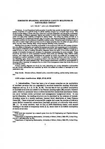
3. Sliding mode control in sampled-data systems The VSS theory was originally developed from a continuous time perspective. It has been realized that directly applying the continuous-time SMC algorithms to discrete-time systems will confront some unconquerable problems, such as the limited sampling frequency, sample/hold effects and discretization errors. Since the switching frequency in sampled-data systems can not exceed the sampling frequency, a discontinuous control does not enable generation of motion in an arbitrary manifold in discrete-time systems. This leads to chattering along the designed sliding surface, or even instability in case of a too large switching gain. Fig. 2 illustrates that in discrete-time systems, the state moves around the sliding surface in a zigzag manner at the sampling frequency.
state trajectory
sliding surface s(x)=0
Fig.6. Discrete-time system with discontinuous control.
As digital computers nowadays are widely involved in the implemetation of control algorithms, it is apparently necessary to develop or generalize the SMC methodology to discrete-time control systems. Actually, a lot of works have been done in this field. Two concepts of discrete-time sliding mode have been suggested for the design of SMC aimed at sampled-data systems.
3.1 Quasi-sliding mode Early contributions on applying the SMC theory in discrete-time systems can be found in (Milosavljevic,1985; Sarpturk, et al., 1987; Furuta, 1990; Sira-Ramirez, 1991). These works were based on the concept of quasi-sliding mode (QSM) introduced by Milosavljevic (1985). Quasi-sliding mode is also termed as “pseudo-sliding mode” by other authors, e.g.,Yu (1994). The concept of QSM is used to express the fact that the conditions for existence of SM in a continuous-time system do not necessarily guarantee the motion of a sampled-data system to bring the state trajec-
29
High Precision Motion Control Based on a Discrete-time Sliding Mode Approach
tory close to the sliding surface. Consider a sampled-data system with the predefined sliding surface x k + 1 = Φx k + Γu k
(41)
s = Λx = 0 The desired state trajectory of a discrete-time VSC system should have the following features: A1) Starting from any initial state, the trajectory will move monotonically towards the switching plane and cross it in finite time. A2) Once the trajectory has first crossed the switching plane, it will cross the plane again in every successive sampling period, resulting in a zigzag motion about the sliding surface. A3) The size of each successive zigzagging step is nonincreasing and hence the trajectory stays within a specified band. Definition 1 (Gao et al.,1995): The motion of a discrete VSC system satisfying the conditions A2 and A3 is called a quasi-sliding mode (QSM). The specified band which contains the QSM is called the quasi-sliding mode band (QSMB) and is defined by { x – ∆ < s ( x ) < +∆ } where 2∆ is the width of the band.
For single input systems, the main approaches for the design of QSM control laws can be categorized into the following two methods: 1) Discrete Lyapunov function based Sarpturk, et al. (1987) noticed that unlike the case in continuous-time SMC, the switching control in the discrete-time case should be both upper and lower bounded in a open interval, in order to guarantee the convergence of sliding mode. Recall that in continuous-time SMC, the control (26) is composed of the equivalent control and a switching control. Converting this control to discrete-time gives u k = u keq + v k
(42)
Hui & Zak (1999) observed that if v k is a relay control with a constant amplitude, the relay must be turned off in some neighbourhood of the surface, in order to reach
30
3. Sliding mode control in sampled-data systems
the switching surface, otherwise, the trajectory will chatter around the surface with a chatter amplitude at least as large as the amplitude of the relay output. The idea of sliding sector (Furuta,1990) was used to solve this problem, i.e., to specify a region in a neighbourhood along the sliding mode, where linear control is used to keep the state inside the region after it has reached the region. The switching control is applied only when system states are out of the region. In this case, the derived switching surface is different from the sliding surface. Based on a discrete Lyapunov function, 1 2 V k = --- s k 2 the reaching law is given by 1 s k ( s k + 1 – s k ) < --- ( s k + 1 – s k ) 2 2
for s k ≠ 0
(43)
which ensures V k + 1 < V k . Furuta (1990) proposed a control law of the type eq
uk = uk + F D xk
(44)
eq
where the equivalent control u k is the solution of ∆s k = s k + 1 – s k = 0
(45)
and therefore the equivalent control for the system (41) is eq
–1
u k = – ( ΛΓ ) Λ ( Φ – I )x k
(46)
F D is a discontinuous control law which will be zero inside the sliding sector. 2) Reaching law based approach Gao et al. (1995) pointed out that the reaching law (43) was incomplete for a satisfactory guarantee of a discrete-time sliding mode, since it does not ensure the conditions A1 and A3. The authors proposed a reaching law based approach for designing the discrete-time sliding mode control law. For a discrete-time system described by (41), the reaching law can be extended from the continuous-time reaching law (34), and for a SISO system, it can be written as s˙( t ) = – ε sgn ( s ( t ) ) – qs ( t ), ε > 0, q > 0
(47)
The equivalent form of the reaching law for discrete-time SMC is s k + 1 – s k = – qT s k – εT sgn ( s k ), ε > 0, q>0, 1-qT>0
(48)
31
High Precision Motion Control Based on a Discrete-time Sliding Mode Approach
where T > 0 is the sampling period. The inequality for T guarantees that starting from any initial state, the trajectory will move monotonically towards the switching surface and cross it in finite time. Then the control law for discrete SMC is derived by comparing s k + 1 – s k = Λx k + 1 – Λx k = ΛΦx k + ΛΓu k – Λx k with the reaching law (48), which yields, –1
u k = – ( ΛΓ ) [ ΛΦx k – Λx k + qT s k + εT sgn ( s k ) ]
(49)
2εT The width of the quasi-sliding mode band is 2∆ = ---------------- . It was shown in Gao et 1 – qT al. (1995) that, in steady state, the trajectory will move within the small band given by { x s ( x ) < εT }
(50)
indicating that the width of the band decreases with decreasing sampling period.
3.2 Discrete-time sliding mode So far the developed sliding mode has always been associated with discontinuities in motion equations. To cope with the sampling frequency limitations of sampled-data controllers, Drakunov & Utkin (1992) introduced a new concept of “sliding mode” for an arbitrary finite-dimensional discrete-time system. As clarified by the authors, the essence of sliding modes in dynamic systems is that a motion exists in some manifold of state trajectories, and that the time to achieve this motion is finite. Hence the discrete-time sliding mode (DSM) is defined by Definition 2: In a discrete-time dynamic system: x ( k + 1 ) = F ( x ( k ) ), x ∈ R
n
(51)
a discrete-time sliding mode takes place on the subset M of the manifold m
S = { x s ( x ) = 0 }, s ∈ R ( m < n ) , if there exists an open neighbourhood U of this subset such that for x ∈ U it follows that s ( F ( x ) ) ∈ M . The authors also characterized the similarity between sliding modes in continuousand discrete-time systems in terms of the non-invertible shift operator. It is known
32
3. Sliding mode control in sampled-data systems
that a general description of dynamic systems in a matrix space X can be expressed mathematically by families of the transformation with shift operator, F ( t, t 0, . ) : X → X
(52)
where F is a continuous function of x, t 0, t ∈ T , t 0 ≤ t ( T ∈ R or Z to embrace continuous and discrete-time cases). For the formulation of the concept of “sliding mode” in dynamic systems, the core idea is that the closed loop systems represented by transformation (52) are not invertible, since the inverse transformation values for states in the sliding manifold are not unique. Therefore we have the following definition: Definition 3: A point x in the state space X of a dynamic system with a family of semigroup transformations { F ( t, t 0, . ) } t ≤ t is said to be a sliding mode point at the moment 0
t ∈ T if for every t 0 ∈ T , t 0 < t , the transformation F ( t, t 0, . ) is not invertible at this point and an equation F ( t, t 0, ζ ) = x has more than one solution ζ . A set Σ ⊂ T × X in the state space is a sliding mode set if for every ( t, x ) ∈ Σ the point x is a sliding mode point at the moment t.
Based on these definitions, the design procedures for discrete-time sliding mode control were developed. For a discrete-time system, the discrete sliding mode can be interpreted as that the states are only required to be kept on the sliding surface at each sampling instant. Between the samples, the states are allowed to deviate from the surface within a boundary layer, see Fig. 3.
state trajectory
sliding surface s(x)=0
Fig.7. Discrete-time sliding mode in sampled-data systems.
Unlike the equivalent control (46) in Furuta (1990), the equivalent control is here derived from the solution of s k + 1 = 0 , which gives
33
High Precision Motion Control Based on a Discrete-time Sliding Mode Approach
–1
eq
u k = – ( ΛΓ ) ΛΦx k
(53)
This indicates that the equivalent control (53) will drive the state onto the sliding surface in one sampling period. Since the control signal in a sampled-data system will show jumps from a continuous time point of view, the formal concept of continuity is not compatible with the notion of discrete-time control. The following definition defines the concept of continuity for discrete time control systems.
Definition 4 (Su, et al., 1996a) The discrete-time control law u k is said to be discontinuous if ∆u k = O ( 1 ) , 2
2
continuous if ∆u k = O ( T ) , smooth if ∆ u k = O ( T ) , where ∆ denotes the –1
backward difference operator 1 – z .
According to definition 4, (53) means that the sliding mode can be generated in discrete-time systems with a continuous function on the right hand side of the system equations. Thus chattering is no longer a matter of concern. This is the most striking contrast between discrete-time sliding mode and continuous-time sliding mode. Furthermore, in continuous-time systems with continuous control, the sliding manifold of state trajectories can be reached only asymptotically, while in discrete time systems with continuous control, sliding motion with state trajectories in some manifold may be reached within a finite time interval (Utkin, 1994).
3.3 Discrete-time sliding mode control of uncertain systems Suppose that the dynamic system (36) satisfies the matching condition (37), such that we can rewrite the system as x˙ = Ax + Bu + Bd
(54)
where, Bd = ∆ Ax + ∆Bu + Ef , in which d is the lumped disturbance. Denoting x ( kT ) = x k , u ( kT ) = u k and d ( kT ) = d k , the discrete-time representation of the system can be obtained by applying a zero-order-hold sampling with sampling period T to the continuous-time process. This gives x k + 1 = Φx k + Γu k + Γd k
34
(55)
3. Sliding mode control in sampled-data systems
where Φ, Γ are obtained from integrating (54) over one sampling time interval t ∈ [ kT , ( k + 1 )T ] , which gives Φ = e
AT
T
Aτ
, Γ = ∫ e dτB . 0
If the control law design is done from a QSM point of view, e.g., using the idea of sliding sector (Furuta, 1990) or from deriving the control by the discrete-time reaching law (48) (Gao, et al., 1995), the selection of F D in (44) and ε in (50) both require knowledge of the disturbance upper bound. The control accuracy is affected by disturbances since the sliding sector and /or quasi-sliding mode band are always dependent on the perturbation. Potential instability and loss of performance due to the use of an attractive and non-invariant switching sector has been discussed in Tang & Misawa (1998). Based on a state feedback switching sector, the authors developed a discrete-time VSC for linear multivariable systems with matched parameter uncertainty. It was found that a conservative bound on uncertainties is usually required in order to obtain a globally, uniformly and asymptotically stable system. In general, holding the continuous-time matching condition does not necessarily mean that the same condition also holds in a discrete-time system since the zeroorder-hold does not take place in the disturbance channels. Hence, the disturbance may not be rejected completely even if discrete-time sliding mode occurs. However, the error introduced due to the fact that the disturbance does not satisfy the matching condition is O ( T 2 ) . In other words, this discrete-time model is an O ( T 2 ) approximation of the exact model described by the same Φ, Γ matrices. From an engineering design perspective, the O ( T 2 ) approximate models are usually adequate since the inter-sampling behaviour of the continuous-time process is also close within O ( T 2 ) to the state values at the sampling instants (Young, et al., 1999). According to the definition 2 and 3, the DSMC is supposed to steer the state of the system (55) towards the sliding surface S and then maintain it on S at each sampling instant, such that s k = Λx k = 0 By solving s k + 1 = 0 , the equivalent control for this perturbed system is obtained as eq
–1
u k = – ( ΛΓ ) ΛΦx k – d k
(56)
(56) is not realizable since it requires complete information of the disturbance d k for eq
computing u k . To solve this problem, a one-step delayed disturbance estimation
35
High Precision Motion Control Based on a Discrete-time Sliding Mode Approach
was used in (Su, et al., 1993, 1996a, 2000, Young, et al., 1999), i.e., to compute the disturbance in the previous sampling instant as Γd k – 1 = x k – Φx k – 1 – Γu k – 1
(57)
Then d k – 1 is used to approximate the current disturbance d k , such that the equivalent control (56) is approximated by –1
u k = – ( ΛΓ ) ΛΦx k – d k – 1
(58)
The very promising feature of this method is that it does not require the knowledge of the disturbance bounds, which makes the control design very simple. The effectiveness of the controller can be immediately seen by applying the control (58) to (55), resulting in the closed-loop dynamics x k + 1 = ( I – Γ ( ΛΓ ) –1 Λ )Φx k + Γ ( d k – d k – 1 )
(59)
where by denoting ∆d k = d k – d k–1 , Γ ∆d k is the control error, or by pre-multiplying Λ to both side of (59), the error can actually be expressed by s k + 1 = ΛΓ∆d k
(60)
We can see that if d k is a constant disturbance, s k + 1 equals zero and does not depend on the magnitude of d k . The effects of different types of uncertainties, namely exogenous disturbances, system parameter variations and control coefficient variations, were analysed in Su, et al. (1996a). It has also been proven that if the disturbance satisfies the boundedness and smoothness conditions, the control (58) is 2
able to constrain the system to stay on an O ( T ) boundary layer of the sliding surface (Su, et al., 2000). It is known that when the state is not on S, the equivalent control (53) tries to drive the state onto the sliding surface in one sampling period. However, if the initial state –1
is far away from S, since ( ΛΓ ) = O ( 1 ⁄ T ) , the magnitude of the control (53) may become infinitely large as T → 0 , this requirement is far beyond the actuator’s limitation. Two methods have been proposed for practical implementation of the control law. One method that was proven by Utkin (1994) takes into account the actuator saturation value u m , by the control law
36
3. Sliding mode control in sampled-data systems
uk uk = uk u m --------uk
if u k ≤ u m (61)
if u k > u m
the system can be forced into the vicinity of discrete-time sliding mode in a finite number of steps. Another approach was proposed in Su, et al. (1993, 1996a). Let S T = { x k ( u k ∈ U ) } denote the O ( T ) boundary layer of S, where U is the set of admissible values of the control u. Then, using a reaching law similar to that defined by Gao (1995), the control law will be of the form uk uk = –1 u k – ( ΛΓ ) Λ ( – s k + K sgn ( s k ) )
if x k ∈ S T
(62)
otherwise
The positive definite matrix K will determine the rate for the state to approach the boundary layer S T . The magnitude of K has to be chosen small enough in order not to over-shoot S T .
37
High Precision Motion Control Based on a Discrete-time Sliding Mode Approach
4. Handling friction by sliding mode control In this thesis, one of the main objectives is to solve the friction problems by SMC. However, friction is neither an exogenous disturbance, nor is the uncertainty in the model parameters that affect natural frequencies of the controlled process. How friction affects the VSC system has not been deeply studied, and so far there are only a few papers investigating the friction problems in such systems. In most control related papers dealing with friction, friction is commonly modelled as stick-slip friction with a discontinuity at zero velocity according to the following: For nonzero velocity, slip friction is F ( x˙), f ( x˙) = – F ( x˙),
if x˙ > 0 if x˙ < 0
(63)
and for zero velocity, stick friction is given by F s, f ( u ) = u, – F s,
if u ≥ F s if – F s < u < F s if u ≤ F s
(64)
where F s > 0 is the amplitude of stick friction and the general model for slip friction is F ( x˙) = F s + ( F s – F c )e
– ( x˙ ⁄ v 0 )
2
+ k v x˙
(65)
In which F c is the constant Coulomb friction force, v 0 is the Stribeck velocity, and k v is the viscous damping. Young (1998, 1999) observed a special behaviour in systems with two discontinuities. The author found that a proper combination of the two discontinuities may create a new class of system trajectories which are closely related to sliding mode. This was studied through a set-point regulation problem of a single degree-of-freedom system of the form mx˙˙ = u – f
38
(66)
4. Handling friction by sliding mode control
where f is the friction described by (63) and which is simply denoted as f = F sgn ( x˙) . If a bang-bang friction compensation u = – u 1 sgn ( x ) is applied to the system (66), a second order system with two discontinuities is formed as mx˙˙ = – u 1 sgn ( x ) – F sgn ( x˙)
(67)
It is observed that for the system (67), if the sliding surface is defined as the intersection of x = 0 and x˙ = 0 , i.e., S xx˙ = { ( x, x˙) S xx˙ = xx˙ = 0 }
(68)
the state of the system can not approach this manifold directly. However, with the bang-bang compensation, sliding mode may occur in the sense of hierarchical control, i.e., sliding mode occurs first on x = 0 , then on the intersection of x = 0 and x˙ = 0 , implying that the origin is asymptotically stable. This special behaviour was discussed in Young (1998) and further investigated in Young (1999). In the later report, by utilizing the sampled-data sliding mode characteristics, the author analysed explicitly the sliding mode hierarchy in the class of systems with two discontinuities. It was shown that when u 1 > F > 0 , the dynamics of such systems will behave in the following manner: 1) A discrete-time sliding mode first occurs on the manifold x = 0 , the “sampling period” is however non-uniform and will tend to zero as time increases. 2) While on x = 0 , x˙ → 0 , but discrete-time sliding mode does not occur at x˙ = 0 since x˙( t j ) is not zero after a finite time. 3) x˙ acts as a substituted “control” (it is not discontinuous but it is changing sign), which keeps the system on x = 0 . In parallel, it was discovered that the class of systems with inherent right hand side discontinuities induce a stiction region in the original system. This stiction phenomenon was generalized and handled within the framework of variable structure controllers by Hatipoglu & Özgüner (1999), and a multi-layer sliding mode controller was proposed for the SISO case. The systems are described in their companion forms with right hand-side discontinuities on p surfaces, (n)
x = f ( x ) + µ ⋅ sgn ( s ( x ) ) + h ( x )v v˙ = u, y = x where µ = [ µ 1 …µ p ] ∈ R
1× p
(69)
n
and h ( . ), f ( . ): R → R are n times smoothly differ-
entiable functions, h ( . ) ≠ 0 for any x = [ x, x˙, …, x ( n – 1 ) ] T , and u, v ∈ R , where u
39
High Precision Motion Control Based on a Discrete-time Sliding Mode Approach
is the control input such that the output y = x tracks the reference signal x d . Further, ε = x – x d denotes the tracking error. First, the sliding surface is defined as s = v – vd = 0
(70)
where v d is an ideal feedback linearization input which has the form 1 v d = --------- { [ x d( n ) – k 1 ε ( n – 1 ) – … – k n – 1 ε˙ – k n ε ] – f ( . ) – µ ⋅ sgn ( s ( . ) ) } h(.)
(71)
So, if v in (69) is replaced by v d , it will lead to a linearized system i.e., the tracking error dynamics is given by, ε ( n ) + k 1 ε ( n – 1 ) + … + k n – 1 ε˙ + k n ε = 0
(72)
By appropriately choosing the parameters k 1, k 2, …, k n , (72) can be made asymptotically stable and ε → 0 at the desired rate. To ensure sliding mode on the surface (70), s˙s < 0 must be satisfied, then for the SMC design, the corresponding control input v˙ is picked as u = v˙ = – α ⋅ sgn ( s ) where α > v˙d + ε . The system will start to slide on the manifold s = 0 after a finite time for any ε > 0 , leading to that v → v d and x → x d . However, v˙d is unbounded around s = 0 since v d contains discontinuities. To avoid this problem, the authors proposed a continuous approximation sgn k ( x ) = ( 2 ⁄ π )arc tan ( kx ) for the discontinuous term sgn ( s ( . ) ) . Further, considering also uncertainties in f ( . ) and/or µ , a multi-layer sliding surface is designed to compensate the uncertainties. This is done by adding an auxiliary discontinuous control into the feedback linearizing control term (71) and replacing the discontinuity with its continuous approximation, i.e., 1 v d = --------- { [ x d( n ) – k 1 ε ( n – 1 ) – … – k n – 1 ε˙ – k n ε ] – f ( . ) – µ ⋅ sgn k ( s ( . ) ) + w } h(.) where f ( . ) and µ correspond to nominal values for the model parameters and w is an auxiliary input, which gives
40
4. Handling friction by sliding mode control
ε ( n ) + k 1 ε ( n – 1 ) + … + k n – 1 ε˙ + k n ε + [ ∆f ( . ) + µΦ k ( s ( . ) ) ± ( ∆µ ⋅ sgn k ( s ( . ) ) – w ) ] = 0
(73)
where the bounded uncertainties in the system parameters are ∆f ( . ) = f ( . ) – f ( . ) , ∆µ = µ – µ , Φ k ( s ) = sgn ( s ) – sgn k ( s ) Then a reduced order manifold can be defined on the second layer sliding surface s ε = ε ( n – 1 ) + c 1 ε ( n – 2 ) + … + c n – 2 ε˙ + c n – 1 ε = 0
(74)
and s ε s˙ε < 0 is proposed to be ensured by the switching law w = ( k 1 – c 1 )ε ( n – 1 ) + … + ( k n – 1 – c n – 1 )ε˙ + k n ε – β ⋅ sgn k ( s )
(75)
where β > ∆f ( . ) + µΦ k ( s ( . ) ) + ∆µ ⋅ sgn k ( s ( . ) ) + ε . This procedure may be repeated until the last manifold depends on the error only. To do this, the discontinuous terms in the manifolds must be replaced with their continuous approximations, thus avoiding to have infinite derivatives at the output. In the case that all states are not measurable, observer based sliding mode control has also been proposed. This design procedure was also used in Drakunov, et al (1997), in which sliding mode control is applied to control a rodless pneumatic servo actuator. After some computations, the motion equation of the piston (and load) is derived as M L Y˙˙ = A T ∆P – µ u Y˙ – µ c sgn ( Y˙ ) where Y is the piston position, M L is the mass of the piston and load, A T is the effective piston area, ∆P = P 1 – P 2 is the pressure drop between chambers, µ u is the viscous friction coefficient and µ c is the Coulomb friction. If the desired pressure value is given by ML 1 ∆P d = ------- [ Y˙˙d – k 1 ( Y˙ – Y˙d ) – k 2 ( Y – Y d ) ] + ------ [ µ u Y˙ + µ c sgn ( Y˙ ) ] AT AT the error dynamics can be linearized as a second order system ˙ε˙ + k 1 ε˙ + k 2 ε = 0 where ε = Y – Y d . The author proposed different designs for set-point regulation and tracking control. For regulation problems, the parameters k 1, k 2 are selected such that they provide an overdamped or critically damped response, i.e., in order to
41
High Precision Motion Control Based on a Discrete-time Sliding Mode Approach
avoid the zero velocity manifold until the desired point ε = 0 is reached, the system must be constrained to approach the desired point from one side without overshooting. For tracking control with the desired trajectory crossing over the zero-velocity manifold σ c = { x˙ = 0 } , sliding mode is achieved through two layers of sliding surfaces. The first layer sliding surface was designed to maintain the pressure on the surface σ = ∆P – ∆P d = 0 in order to compensate uncertainty due to modelling errors. Then the second layer sliding surface s = ε˙ + cε = 0, c > 0 , could be reached in finite time. In summary, these works on handling friction focus on variable structure controllers for continuous-time systems. Since the friction is viewed as a discontinuous function at zero velocity, the stiction manifold induced by this discontinuity can, according to Hatipoglu & Özgüner (1999), only be shrunk or entirely eliminated by applying another discontinuous control in the same subspace as the discontinuous disturbance. Although the discontinuous control terms can be approximated by a continuous function, a high bandwidth controller is needed to reduce the tracking errors. However, such controllers are not always applicable since they may intensely excite the motion of flexible components in the process. Moreover, the proposed controller/ observer structures will in practice be implemented in discrete time with a finite sampling rate 1/T, leading to significant chattering around the reference and in the corresponding control signals, this phenomenon has been observed in the simulation results of Hatipoglu & Özgüner (1999).
42
5. Handling mechanical flexibility in variable structure systems
5. Handling mechanical flexibility in variable structure systems The insensitivity of sliding mode control to parameter uncertainty and external disturbances has been demonstrated in the control of rigid systems (Slotine & Sastry, 1983; Eun, et al., 1999; Lee & Lee, 1999; Golo & Milosavljevic, 2000). However, care must be taken when designing SM/DSM controllers for flexible systems, since the oscillating motion of flexible components in such systems may be unduly excited by the SM control inputs. To avoid oscillations while preserving the insensitivity of the sliding mode, different approaches to be combined with sliding mode control have been proposed. The most frequently cited method is the frequency-shaped sliding mode (FSSM) introduced by Young & Özgüner (1993). Unlike the conventional sliding surface which is the intersection of hyperplanes in the process state space, the frequency-shaped switching surface is a linear operator, through which compensator dynamics are introduced. Here we will make a brief review of the design methods. Consider a process model which can be transformed to the following form x˙1 = A 11 x 1 + A 12 x 2 x˙2 = A 21 x 1 + A 22 x 2 + B 2 u
(76)
and define the sliding surface as s ( x ) = Λ ( x1 ) + x2
(77)
where Λ is a linear operator. Either pole-placement or linear quadratic (LQ) optimal methods can be used to design the desired dynamics of the sliding surface, i.e., to find Λ ( x 1 ) . 1) Pole-placement design Λ ( x 1 ) can be realized as a dynamic system z˙ = Fz + Gx 1 y = Hz + Lx 1
(78)
The augmented system is F z˙ x˙1 = 0
A 11
x˙2
A 21
0
G
0 z 0 A 12 x 1 + 0 u B2 A 22 x 2
43
High Precision Motion Control Based on a Discrete-time Sliding Mode Approach
Then the sliding surface is s ( x 1, x 2 , z ) = [ H L ]
z + x2 x1
(79)
When s = 0 , the equation of sliding mode is z˙ = x˙1
F A 12
G z A 11 – A 12 L x 1
and all its poles can be placed by the selection of { F , G, H , L } if ( A 11, A 12 ) is controllable. 2) Optimal frequency-shaped LQ design For the system (76), the quadratic cost function in the frequency domain can be written as J s = ∫∞–∞ [ x 1* ( jω )Q 11 ( ω )x 1 ( jω ) + x 2* ( jω )Q 22 ( ω )x 2 ( jω ) ] dω
(80)
where Q 11 ( ω ) ≥ 0, Q 22 ( ω ) ≥ 0 for all frequencies ω . There exists four cases: (a) both Q 11 and Q 22 are constant for all frequencies (b) Q 22 is function of ω 2 and Q 11 is constant for all frequencies (c) Q 11 is function of ω 2 and Q 22 is constant for all frequencies (d) both Q 11 and Q 22 are functions of ω 2 Case (a) has already been described in section 2.2.1 on page 17. For cases (b) and (c), remember that x 2 is viewed as a control input to the reduced-order system during sliding mode, so selecting high-pass frequency characteristics for the elements of Q 22 ( ω ) is equivalent to minimizing high frequency control input to the system. Similarly, by choosing low-pass characteristics for Q 11 ( ω ) , the low frequency motion of the system is penalized. Therefore, case (b) corresponds to designing a pre-compensator and case (c) corresponds to designing a post-compensator. It has been shown that if Q 11 and Q 22 are the inverse of each other, identical closed-loop poles and an optimal sliding mode can be obtained for the cases b) and c) (Young & Özgüner, 1993). Here the design of case (b) is presented.
44
5. Handling mechanical flexibility in variable structure systems
Choosing Q 11 = 1 and Q 22 of high-pass characteristic as represented by a spectral factor W 2 ( jω ), i.e., Q 22 ( ω ) = W 2* ( jω )W 2 ( jω ) then (80) becomes J s = ∫∞–∞ [ x 1* ( jω )Q 11 ( ω )x 1 ( jω ) + ( W 2 ( jω )x 2 ( jω ) ) * W 2 ( jω )x 2 ( jω ) ] dω = ∫∞ [ x 1* x 1 + u˜ * u˜ ] dt ts
where u˜ ( s ) = W 2 ( s )x 2 ( s ) is regarded as the output of a filter or a dynamic system represented by z˙ = Fz + Gx 2 u˜ = Hz + Dx 2
(81) –1
The transfer function of (81) is W 2 ( s ) = D + H ( sI – F ) G , and x 2 is the input. Consider the augmented system which is the original system extended with the above dynamic compensator (81) x˙e = A e x e + B e x 2 where A e = diag ( F , A 11 ) , B e = [ G A 12 ] T and x e = [ z x 1 ] T . The optimal sliding surface for the augmented system can now be obtained by minimizing ∞
J = ∫t ( x eT Q e x e + 2x eT N e x 2 + x 2T R e x 2 ) dt s The sliding surface is: s ( x 2, x e ) = x 2 + K x e
(82)
–1
where, K = R e ( B eT P e + N eT ) , P e is the solution of the Riccati equation –1
A eT P e + P e A e – ( P e B e + N e ) R e ( B eT P e + N eT ) = – Q e and Q e = diag ( H T H , Q 11 ) , R e = D T D , N e = [ H T D 0 ] T . Let K = [ K 1 K 2 ] , and then (82) becomes s = x2 + K 1 z + K 2 x1
(83)
which is a linear combination of the states of the following extended system
45
High Precision Motion Control Based on a Discrete-time Sliding Mode Approach
F z˙ x˙1 = 0
A 11
x˙2
A 21
0
0
G z 0 A 12 x 1 + 0 u B2 A 22 x 2
Note that the selection of weighting functions is important in the design. Different weighting functions will result in different sliding surfaces. Koshlouei & Zinober (2000) developed an iterative optimal design procedure, i.e., by comparing the eigenvalues of the reduced-order system, the sliding surface can be constructed iteratively until the desired surface has been obtained. The authors further extended the method to the case when all weighting functions are frequency-dependent, i.e. the case (d). Frequency-shaped sliding mode control based on H_inf and µ synthesis was also studied by Nonami, et al.(1996). It is seen that the basic idea of the above frequency-shaping is to insert a filter with an appropriate cut-off frequency into the sliding surfaces, and thus high frequency vibrations due to interactions between the unmodelled dynamics and the sliding mode control can be damped out in the designated frequency band. The price is that the response of the closed loop system may be significantly slowed down during sliding mode. Further, since sliding motion occurs only after the system has reached the sliding surface, the controller is actually a conventional state feedback control in the reaching phase and hence the controlled system may be sensitive to uncertainties. Since the FSSM method does not consider system constraints during the reaching phase, the unmodelled dynamics may be excited already during this period, leading to system oscillation or instability. Other methods to avoid vibrations in SMC controlled flexible systems can also be found in the literature. These methods include frequency shaped sliding mode with the combination of terminal sliding mode control (TSMC) (Xu & Cao, 2000), where TSMC is specified by an increasing equivalent switching slope as tracking error decreases, thus quickening the convergence of the tracking error; Frequency shaped sliding mode with perturbation estimation to reduce the switching gain (Moura, et al., 1997a, 1997b); Sliding mode with shaped command input to remove undesired frequency components from the control signal (Singh, 1994; Jalili & Olgac, 1998) and sliding mode with time-varying or nonlinear sliding surface to eliminate reaching phase (Hara & Yoshida, 1996; Li, et al, 1999). Notably, most frequency-shaped methods were approached in the continuous-time domain. How to handle flexibility problems, especially the unmodelled dynamics in discrete-time SMC has not obtained much attention. One example was found in Pieper & Surgenor (1993), in which the authors designed a DSMC for speed control
46
5. Handling mechanical flexibility in variable structure systems
of an elastic system. The sliding surface was designed by LQ optimization without using frequency shaping, instead a dynamic switching gain was proposed to damp the oscillatory modes due to the unmodelled dynamics, so as to increase the stability and robustness of the controlled system.
47
High Precision Motion Control Based on a Discrete-time Sliding Mode Approach
6. Summary of the appended papers Paper A introduces the use of DSMC with delayed disturbance compensation for friction cancellation in a high precision point-to-point positioning system. Paper B further proposes a model reference DSMC for high precision tracking control, and the influence of the choice of sampling period on friction compensation is analysed by simulation. Paper C combines DSMC with a vibration filter and hence proposes a new method, referred to as DSMVC for controlling a flexible system with unmodelled dynamics. Paper D intends to design a positioning controller for twomass systems whose resonance ratio may vary in a wide range. A frequency-shaped resonance ratio control is proposed, and combined with the DSMVC, such that high accuracy, fast response positioning control is achieved. The experimental systems used in the four papers are sketched as the following. The experimental setup 1, a linear motor system, is used in Paper B (Paper A uses the same linear motor with a similar setup). As shown in Fig. 8, the motor itself has only two components, i.e. the thrust rod and the thrust block which is mounted on a bearing rail. For studying control problems associated with friction, another aluminium bar with a friction adjustment device is mounted as shown in the figure. The motor is current controlled and an optical encoder with resolution of 0.5µm/step is installed. The velocity feedback signal is obtained by the backward difference of two successive position signals. adjustable friction
thrust rod enclosed magnets
motor m
bearing rail
thrust block enclosed coil
Fig.8. The experimental setup 1 --- a linear motor system.
The experimental setup used in Paper C is shown in Fig. 9. This is the so called Yaxis of a surface mount robot, the rotation of a current controlled DC motor is converted into a translational motion by a high precision ball-screw. A slide table attached to the ball-nut carries the load at high velocities. The total moving range along the Y-axis is 1.2 meters. The position is measured by an incremental encode
48
6. Summary of the appended papers
with resolution of 2µm/step mounted on the motor, and the velocity signal is also obtained by the backward difference of two successive position signals. Disturbances and friction torques are assumed to act only at motor side in this application.
x l, x˙l Table & Load
Ball bearing
Nut
DC
θm
Ball-screw
Slide bearing Flexible connection Ball bearing
im Coupling
Fig.9. The experimental setup 2 --- the Y-axis of the surface mount Robot (SMR) from MYDATA.
The experimental setup of the two-mass system for Paper D uses the same drive system and measuring equipment as that of the setup 1. In addition, another mass is connected to the motor by two thin steel plates, which introduces the mechanical resonance. ∆x x2
load m2
flexible links
ks/2
ks/2
thrust rod enclosed magnets x1
motor
m1
bearing rail
b1 thrust block enclosed coil
Fig.10. The experimental setup 3 --- the two-mass system.
6.1 Friction compensation DSMC with one-step delayed disturbance compensation is successfully applied to control a linear motor system with high friction (Paper A, B). The advantage of using the discrete-time SMC is that the control does not involve the switching term, thus avoiding the chattering problems. Recall the control error expressed by (59) or
49
High Precision Motion Control Based on a Discrete-time Sliding Mode Approach
(60) in section 4.3, and for simplicity assume that the disturbance d k mainly is due to friction, then the error given by (60) utterly depends on the difference in friction between two successive sampling instances, i.e, ∆d k = d k – d k – 1 . Considering the real physical phenomena behind friction, it is clear that friction can not be accurately modelled by a pure discontinuity as given by classical friction models, instead friction is a continuous function of time with complicated and fast dynamics in the vicinity of zero velocity. Intuitively, T → 0 also results in that ∆d k → 0 , i.e., a faster sampling rate results in a better friction cancellation. However, it must also be noted that a small T will result in a large control input, and both the actuator limitation (i.e., u ≤ u m ) and the features of DSMC (recall the control law of (61) or (62)) may cause the control signal to chatter with the amplitude of ± u m , which in turn leads to high frequency oscillations in the system. Therefore, how fast a sampling rate is needed depends on the required control accuracy, and also on how fast the friction dynamics is in the vicinity of zero velocity. This was investigated in Paper B through simulation with the LuGre friction model. It is shown in experiments that a sampling rate higher than 100Hz is enough for avoiding limit cycles and achieving good friction compensation for point-to-point positioning. For tracking reference trajectories which cross zero velocity, higher sampling may be used to reduce the errors around the zero velocity crossings. According to the common rule of thumb, the choice of sampling frequency in a digital control must usually be in the range of 10-20 times of the desired closed-loop bandwidth. For the specific high speed and high precision systems used through Paper A to D, the sampling rate is typically selected as 500-1000Hz. Comparing to this frequency, the frequency required for friction compensation does actually not need any special consideration. Therefore, the selection of T may only take into account the dominant poles of the controlled process and the required control bandwidth. Paper A shows experimentally that given a straight forward VSC design for setpoint regulation, the final reaching of the desired position accuracy depends only on the selection of sampling period T without any knowledge of the friction. When T is large (T=0.02s), low-frequency limit cycles occur around the final position. When the sampling period decreases (T= 0.012s), limit cycles can be entirely avoided and steady-state error equal to the sensor resolution can be achieved. For evaluation, the performance of DSMC is compared with digital PID and PD controllers, where the same one-step delayed disturbance compensation is introduced in all the controllers. Comparison shows that robust positioning performance can only be achieved by the DSMC for both long distances (10 mm) and short distances (in the order of sensor resolution, 2µm) positioning. PD control can only bring the system close to the goal
50
6. Summary of the appended papers
and a much longer positioning time is required. Adding an integrator, i.e., applying PID control does not improve the performance, instead it results in limit cycles. The tracking problem is further investigated in Paper B. It is shown that when the desired trajectory crosses the zero velocity surface, the disturbance estimation error ∆d k is usually of large value due to the fast friction dynamics, i.e., resulting in a large difference between dk-1 and dk. In general, it is difficult to cancel the friction in case the reference trajectory crosses zero velocity, however, it is still possible to reduce ∆d k by reducing the sampling period according to the previous discussion. A model reference sliding mode controller is designed for the control of a linear motor system in order to accurately control both transient and steady-state position tracking. Moreover, by combining an additional integral action with the DSMC, the tracking errors around zero velocity are significantly reduced and the overall tracking performance is also greatly improved.
6.2 Vibration suppression Paper C and D studies how to handle the unmodelled dynamics in DSM controlled systems. Transmissions or links which are necessary in mechanical systems are in general of finite stiffness, and the induced resonance modes are often close to the required control bandwidth. To avoid exciting these high frequency modes, care must be taken during applying the DSMC to such a control system. For example, recall the DSMC law (58) in section 3.3, where dk-1 represents the estimated disturbances. It must be noted that dk-1 may contain not only low frequency disturbances, but also high frequency components due to those unmodelled dynamics. Directly feeding dk-1 to the input may magnify those high frequency components thus resulting in high frequency oscillations in the closed loop. In Paper C, DSMC is applied to an industrial application in the form of a DC motor and ball-screw driven high precision positioning system (Fig. 9), being one axis in a multi-axis surface mount robot. Finite stiffness of the ball-screw and other flexible links induce several high frequency modes into the system, while only the motor position can be sensed. In this paper, a simple method to suppress the potential vibrations is proposed. That is done by bringing in a low-pass filter Q ( q ) into the disturbance observer loop, such that with a proper cut-off frequency, the higher order vibrations in the system can be effectively suppressed. This method is very simple. As the process is simplified as a two-mass system, the design only requires knowledge of the lumped mass associated with the motor side and the range of the first resonance mode.
51
High Precision Motion Control Based on a Discrete-time Sliding Mode Approach
The method based on DSMC with vibration suppression, i.e., DSMVC, proposed in Paper C, is the basis for further research on the control of two-mass systems with different mass distribution. This study is motivated by the fact that many industrial processes can be modelled with two masses connected by a flexible link, while sensors are often attached only on the first mass, hence the achievable loop gains are significantly limited due to resonant vibrations. It is known that the dynamics of a two-mass system can be characterized by its resonance ratio, which in turn is determined by the ratio of the two masses. So far there has been no general method for controlling such two-mass systems with wide variation in resonance ratio. The ambition of Paper D is to develop a control method to cope with vibration problems in two-mass systems with different mass distribution. The concept of resonance ration control (Suriura & Hori, 1994) is adopted and improved with frequencyshaped characteristics, i.e., the virtual resonance ratio of a two-mass system is increased by dynamically feeding back the estimated disturbance. The new vibration suppression method has been successfully combined into the DSMVC to effectively suppress the resonant vibrations. The DSM controller and the resonance ratio controller can be designed independently, which makes the design very simple and easy to apply to different systems with wide variation in resonance ratio.
6.3 Summary of the contributions • Successful application of the discrete-time sliding mode control (DSMC) to
electrically driven high precision motion control systems. The designed controllers are robust and chattering free. • The utilization of one-step delayed disturbance compensation alleviates the most
difficult work on friction compensation, i.e., the modelling and identification of friction become unnecessary. Simulation analysis and experimental verification show that, with this method, the accuracy of friction compensation depends mainly on the selection of sampling frequency. • The provision of a simple and effective method for handling flexibility in DSMC
systems, i.e., introducing a LP vibration filter Q ( q ) in the disturbance compensation loop, by which high frequency vibrations due to unmodelled dynamics can be effectively suppressed. • The proposed frequency-shaped resonance ratio control (FSRRC) enables the
dynamic adaptation of the virtual resonance ratio of a two-mass system.
52
6. Summary of the appended papers
• The combination of the proposed DSMC and FSRRC provides an effective and
robust method for controlling two-mass systems with wide resonance ratio variation.
53
High Precision Motion Control Based on a Discrete-time Sliding Mode Approach
7. Conclusions, discussions and future works Based on the excellent properties of SMC and the new definition of DSM, this thesis presents a control methodology which successfully solves two of the major difficulties -- friction compensation and vibration suppression -- in high performance motion control systems. By the proposed approach, the desired performance can be specified in terms of the sliding surface which is independent from the choice of the control, and a robust, accurate and chattering free controller can be obtained based on a second order nominal process model. The control algorithms are simple and straightforward, without the need for friction modelling and identification techniques and without employing any complicated on-line adaptive algorithms. To further improve the developed concepts and to facilitate practical and industrial usage of the results, there are still some issues open to further research. Further study of the stability conditions for the DSM controlled flexible systems is needed. It has been noted that if tracking control is required in two-mass systems, the tracking error can not simply be reduced by introducing an integrator as it has been done in Paper B for a rigid system, especially when the system is perturbed by friction. More in-depth analysis of the interaction between DSMC and friction, so as to find an explicit relation between the sampling rate and the parameters of the dynamic friction is also of interest. Furthermore, it must be noted that so far have the proposed methods only been applied to a specific class of electrically driven systems, i.e., the following conditions are satisfied: 1) The dynamics of the actuators (electrical motors) is negligible. 2) For two-mass systems, the sensor is attached on the first mass, and the resonance mode is outside the required closed-loop bandwidth. 3) Disturbances (including friction) act only on the first mass. Certainly, it would be interesting to apply the proposed method to different types of systems. However, doing this may immediately lead to violation of the above conditions. Hence, as a natural extension, future works could be focused on solving the following problems: First, if the condition 1 or 3 is not satisfied, the matching conditions for disturbance rejection and insensitivity to parameter variations in SM are violated, hence the desired sliding mode can in general not be maintained. Some control methods have been developed to combat unmatched disturbances. The restriction on matching conditions may be relaxed by introducing higher order sliding mode (Fridman & Levant, 1996; Eaton, et al., 1999; Jiang, et al., 1999). Discrete-time implementation
54
7. Conclusions, discussions and future works
of second order sliding mode control has been presented by Bartolini, et al., (1999a, b; 2001). Young, et al. (1999) also demonstrated the design of continuous-time SMC with prefilter for the case when the dynamics of the actuator can not be neglected. However, these methods require derivatives of the states in the feedback control implementation, and moreover, the disturbances must be restricted to the class which have bounded derivatives. No paper has been found which deals with unmatched friction disturbances. Second, for two-mass systems, if the sensor is attached on the second mass, the control loop will encompass the resonance mode. Even if this resonance frequency is outside the desired bandwidth, it induces oscillations in the control loop. Therefore the resonance mode can no longer be neglected in process modelling, i.e., the process model has to be at least of fourth order. Asymptotic observers may be utilized for estimating the immeasurable states (Utkin, 1992). One study on observer based discrete sliding mode control can be found in Richter (1997). The consideration of other nonlinearities, such as backlash, hysteresis, etc., also existing in the electro-mechanical systems may also be included in controller design. This may require another possible path for future works, i.e., to combine the SMC with other advanced control technology, such as fuzzy logic, neural networks and learning control.
55
High Precision Motion Control Based on a Discrete-time Sliding Mode Approach
Bibliography Armstrong-Helouvry, B. (1991). Control of machines with friction. Kluwer Academic Publisher, Norwell, MA. Armstrong-Helouvry, B., Dupont, P. & Canudas de Wit, C. (1994). A survey of models, analysis tools and compensation methods for the control of machines with friction. Automatica 30(7), 1083-1183. Bartolini, G. & Pydynowski, P. (1996). An improved, chattering free, VSC: scheme for uncertain dynamics systems. IEEE Transaction on Automatic Control, 41(8), August. Bartolini, G., Ferrara, A. & Giacomini, L. (1997). A simplified adaptive control scheme based on a combined backstepping/second order sliding mode algorithm. Proceedings of American Control Conference, Albuquerque, New Mexico, June. Bartolini, G., Ferrara, A. & Usai, E. (1998). Chattering avoidance by second-order sliding mode control. IEEE Transactions on Automatic Control, 43(2), February. Bartolini, G., Ferrara, A. (1999). On the parameter convergence properties of a combined VS/Adaptive control scheme during sliding mode. IEEE Transactions on Automatic Control, 44(1), January. Bartolini, G., Ferrara, A., Levant, A. & Usai, E. (1999a). On second order sliding mode controllers. Variable Structure Systems, Sliding Mode and Nonlinear Control. -(Lecture Notes in Control and Information Science 247). Young & Özgüner (Eds), Springer-Verlag London Limited. Bartolini, G., Pisano, A. & Usai, E. (1999b) Variable structure control of nonlinear sampled data systems by second order sliding modes. Variable Structure Systems, Sliding Mode and Nonlinear Control. -(Lecture Notes in Control and Information Science 247). Young & Özgüner (Eds), Springer-Verlag London Limited. Bartolini, G., Pisano, A. & Usai, E. (2001). Digital second-order sliding mode control for uncertain nonlinear systems. Automatic, 37, pp 1371-1377. Bliman, P.-A., & Sorine, M. (1995). Easy-to-use realistic dry friction models for automatic control. Proceedings of 3rd European Control Conference, Rome, Italy. pp: 3788-3794. Brandenburg, G. & Schäfer, U. (1990). Design and performance of different types of
56
Bibliography
observers for industrial speed- and position-controlled electromechanical systems. Electrical Drives and Power Electronics. Canudas de Wit, C., Olsson, H., Åström, K.J. & Lischinsky, P. (1995). A new model for control system with friction. IEEE Trans. of Automatic Control 40(3), 419425. Canudas De Wit, C.; Ge, S.S. (1997). Adaptive friction compensation for systems with generalized velocity/position friction dependency. Proceedings of the 36th IEEE Conference on Decision and Control, Vol. 3, 2465 -2470 Canudas de Wit, C & Lischinsky, P. (1997). Adaptive friction compensation with partially known dynamic friction model. Int. J. of Adaptive control and signal processing 100, 65-80. Chun, Y. & Hori, Y. (1994). Rolling mill controller design with H ∞ sensitivity minimization. First Asian Control Conference, Vol.2, pp-629-632, Tokyo. Choi, S-B., Cheong, C-C. & Park, D-W. (1993). Moving switching surfaces for robust control of second-order variable structure systems. International Journal of Control, 58(1), 229-245. Colombi, S. & Raimondi, T. (1994). Compliance compensation in mechatronic systems. IEEE 20th International Conference on Industrial Electronics, Control and Instrumentation, IECON’94, Vol.: 2, pp: 946 -951 Dahl, P. R. (1968). A Solid Friction Model. Aerospace Corp., EL Segundo, CA, Tech. Rep. Tor-0158(3107-18)-1, 1968. DeClarlo, R.A., Zak, S. H. & Mathews, G. R. (1988). Variable structure control of nonlinear multivariable systems: A Tutorial. Proceedings of IEEE, Vol.76 No.3, pp 212-232. Dhaouadi, R., Kubo, K. & Tobise, M. (1991). Robust speed control of rolling mill drive systems using the loop transfer recovery design methodology. Proceedings of IECON’91. pp. 555 -560 vol.1 Dhaouadi, R.; Kubo, K. & Tobise, M. (1993). Two-degree-of-freedom robust speed controller for high-performance rolling mill drives. IEEE Transactions on Industry Applications. 29(5), 919 -926 Dhaouadi, R.; Kubo, K. & Tobise, M. (1994). Analysis and compensation of speed drive systems with torsional loads. IEEE Transactions on Industry Applications,
57
High Precision Motion Control Based on a Discrete-time Sliding Mode Approach
30(3), 760 -766 Drakunov, S.V. & Utkin, V. I. (1992). Sliding mode control in dynamic systems. International Journal of Control, 55(4),1029-1037. Drakunov, S.V., Hanchin, G.D., Su, W.C. & Özgüner, Ü. (1997). Nonlinear control of a rodless pneumatic servoactuator, or sliding modes versus Coulomb friction. Automatica, 33(7): 1401-1408. Eaton, R., Hesketh, T. & Clements, D. J. (1999). Dynamics sliding mode control of perturbed nonlinear systems in strict feedback form. Proceedings of the 38th conference on Decision & Control, Phoenix, Arizonz, USA. Eun, Y., Kim, J-H., Kim, K. & Cho, D-I. (1999). Discrete-time variable structure controller with a decoupled disturbance compensator and its application to a CNC servomechanism. IEEE Transaction on Control System Technology, 7(4), July. Elmali, H. & Olagac, N. (1992). Sliding mode control with perturbation estimation (SMCPE): a new approach. International Journal of Control, 56(4), 923-941 Fridman, L. & Levant, A. (1996). Higher order sliding modes as a natural phenomenon in control theory. Robust Control via Variable Structure and Lyapunov Techniques. ISBN 3-540-76067-9 Springer-Verlag Berlin Heideberg, New York. Furuta, K. (1990). Sliding mode control of a discrete system. Systems and Control Letters, 14, 142-152. Furuta, K. & Pan, Y. (1999). Variable structure control of continuous-time with sliding sector. IFAC’99, Beijing, China. Furuta, T. & Tomiyama, K.(1996). Sliding mode control with time-varying hyperplane. Proceedings of IROS 96. Gao, W. B. & Hung, J. C. (1993) Variable structure control of nonlinear system: a new approach. IEEE Transaction on Industrial Electronics, 40(1), Feb. Gao, W. B., Wang, Y. & Homaifa, A. (1995). Discrete-time variable structure control systems. IEEE Transaction on Industrial Electronics, 42(2), April. Ge, S.S., Lee, T.H. & Ren, S.X. (1999). Adaptive friction compensation of servo mechanisms. Proceedings of the IEEE International Conference on Control Applications, Vol. 2, pp 1175 -1180 Golo, G. & Milosavljevic, C. (2000). Robust discrete-time chattering free sliding
58
Bibliography
mode control. Systems & Control letters, 41, 19-28 Haessig, D.A. & Friedland, B. (1991). On the modelling and simulation of friction. Journal of Dynamics Systems, Measurement and control. 113(3): 354-362, September. Hara, S. & Yoshida, K. (1996). Simultaneous optimization of positioning and vibration control using time-varying frequency-shaped criterion function. Control Engineering Practice 4(4), 553-561. Haskara, I. & Özgüner, ü. (1999). An estimation based robust tracking controller design for uncertain nonlinear system. Proceedings of the 38th Conference on Decision &Control, Phoenix, Arizona USA. Hatipoglu, C. & Özgüner, Ü. (1999). Handling stiction with variable structure control. Variable Structure Systems, Sliding Mode and Nonlinear Control. (Lecture Notes in Control and Information Science 247). Young & Özgüner (Eds), springer-Verlag London Limited 1999. Hirata, M., K.Z. Liu and T. Mita (1996). Active vibration control of a 2-mass system using µ-synthesis with a descriptor form representation. Control Eng. Practice, Vol. 4, No. 4, pp 545-552. Hori, Y., Iseki, H. & Sugiura, K. (1994). Basic consideration of vibration suppression and disturbance rejection control of multi-inertia system using SFLAC (state-feedback and load acceleration control). IEEE Trans. on Industrial Applications., 30(4), 889-896. Hori, Y. (1995a). Comparison of torsional vibration controls based on the fast and slow disturbance observers. IPEC’95, Vol:1, pp 440-446. Hori, Y. (1995b). Vibration suppression and disturbance rejection control on torsional systems. IFAC Motion Control, pp 40-50, Munchen. Hori, Y. (1996). A review of torsional vibration control methods and proposal of disturbance observer-based new techniques. IFAC, 13th Triennial World Congress, San Francisco, USA. Hori, Y., Chun, Y. & Sawada, H. (1996). Experimental evaluation of disturbance observer-based vibration suppression and disturbance rejection in torsional system. Proc. of PEMC’96, Budapest. Hori, Y.; Sawada, H.; Chun, Y. (1999). Slow resonance ratio control for vibration
59
High Precision Motion Control Based on a Discrete-time Sliding Mode Approach
suppression and disturbance rejection in torsional system. IEEE Transactions on Industrial Electronics, 46 (1), 162 -168 Hsien, T.L., Y.Y. Sun, M.C. Tsai and S.J. Huang (1997). Robust servo control system design for two flexibly linked masses. Control Eng. Practice, Vol. 5, No. 7, pp 951-961. Hsu, Y-L. (1995). Sliding mode control of robot manipulators. Ph.D thesis, Univ. Louvain. Belgium. Hui, S. & Zak, S. H. (1999). On discrete-time variable structure sliding mode control. System & Control Letters 38, pp283-288. Hung, J. Y. (1991). Control of industrial robots that have transmission elasticity. IEEE transaction on Industrial Electronics., 38, pp. 421-427. Hung, J. Y., Gao, W. & Hung, J. C. (1993). Variable structure control: A survey. IEEE transaction on Industrial Electronics., 40(1), February. Iseki, H., & Hori, Y.(1994). Advance controller for two-mass-system using loopshaping design techniques. 3rd International Workshop on Advance Motion Control. Berkeley. Jalili, N. & Olgac, N. (1998). Time-optimal/sliding mode control implementation for robust tracking of uncertain flexible structures. Mechatronics 8,121-142. Jiang, Y. A., Hesketh, T. & Clements, D.J. (1999). High order sliding mode control of uncertain linear systems. Proceedings of 14ht IFAC, Beijing. Johnson, C. T. and R. D. Lorenz (1992). Experimental identification of friction and its compensation in precise, position controlled mechanisms. IEEE Trans. on Industry Application, Vol. 28, No. 6, November/december Koshlouei, A. J. & Zinober, A.S.I. (2000). Robust frequency shaping sliding mode control. IEE Proc.-Control Theory Appl 147(3). Kidron, O. & Yaniv, O.(1995). Robust control of uncertain resonant systems. European Journal of Control, 1(2). Kim, K-S., Park, Y. & Oh, S-H. (2000). Designing robust sliding hyperplanes for parametric uncertain systems: a Riccati approach. Automatica, 36, 1041-1048. Lee, S.M. & Lee, B.H. (1999). A discrete-time sliding mode controller and observer with computation time delay. Control Engineering Practice, 7, 943-955
60
Bibliography
Lee, S-W. & Kim, J-H. (1999). Friction identification using evolution strategies and robust control of positioning tables. Journal of Dynamic systems, Measurement, and Control 121, December. Lee, H. S. & Tomizuka, M. (1996). Robust motion controller design for highaccuracy positioning systems. IEEE Transactions On Industrial Electronics 43(1), February. Li, Y-F, Eriksson, B. & Wikander, J. (1999). Sliding mode control of two-mass systems. Proceedings of IFAC’99, Vol. C, 151-156. Beijing, China, 5-9 July. Milosavljevic, C. (1985). General conditions for the existence of a quasi-sliding mode on the switching hyperplane in discrete variable structure systems. Automation and Remote control, 46, 307-314. Moura, J. T., Roy, R. G. & Olgac, N. (1997a). Sliding mode control with perturbation estimation (SMCPE) and frequency shaping sliding surfaces. Transactions of the ASME 119, September, 1997. Moura, J. T., Roy, R. G. & Olgac, N. (1997b). Frequency-shaped sliding modes: analysis and experiments. IEEE Transactions on Control Systems Technology, 5(4), July, 1997. Nonaka, K., Yasaki, Y. & Furuta, K. (1996). A study on model reference variable structure control with adaptive sliding surface. Proceedings of 35th Conference on Decision and Control. Nonami, K., Ito, T., Kitamura, Y. & Iwabuchi, K. (1996). Frequency-shaped sliding mode control using H_inf control and µ synthesis theory. IEEE Workshop on Variable Structure Systems. Nordin, M. & Gutman, P.-O. (1996). Digital QFT-design for the benchmark problem. European Journal of Control, 1(2), 97-103. Nordin, M. (2000). Nonlinear backlash compensation for speed controlled elastic systems. Ph.d Thesis, Dept. of Mathematics, Royal Institute of Technology, Stockholm, Sweden. TRITA-MAT-00-OS-03, ISSN 1401-2294. Olsson, O. (1996). Control systems with friction. PhD thesis. ISRN LUTFD2/TFRT-1045--SE, April 1996. Department of Automatic Control, Lund Institute of Technology, Lund, Sweden. Olsson, O., Åström, K.J., Canudas de Wit, C., Gäfvert, M. & Lischinsky, P. (1998).
61
High Precision Motion Control Based on a Discrete-time Sliding Mode Approach
Friction models and friction compensation. European Journal of Control, 1998. Pieper, J.K. & Surgenor, B.W. (1993). Discrete sliding control of a coupled-drives apparatus with optimal sliding surface and switching gain. IEE Proceedings of Control Theory and Applications, Volume: 140 Issue: 2, pp: 70 -78, March. Popovic, M. R., D. M. Gorinevsky, A.A Goldenbery (1995). A study of response to short torque pulses and fuzzy control of positioning for devices with stick-slip friction. Proceedings of the 4th IEEE Conference on Control Applications, pp: 302 -307. Richter, H. (1997), Hyperplane design in observer-based discrete-time sliding mode control. Master Thesis, Oklahoma State University, School of Mechanical & Aerospace Engineering, Advance Control Laboratory, ACL-98-002. Sarpturk, S.Z., Istefanopulos, Y. & Kaynak, O. (1987). “On the stability of discretetime sliding mode control systems. IEEE Transactions on Automatic Control, 32(10), 930-932. Schäfer, U. and G. Brandenburg (1989). Compensation of coulomb friction in industrial elastic two-mass systems through model reference adaptive control. Proc. of 3rd European Conference on Power Electronics and Applications. Schäfer, U. and G. Brandenburg (1990). Model reference position control of an elastic two-mass system with backlash and coulomb friction using different types observers. Power Electronics and Motion Control, PEMC’90. Singh, T. (1994). Sliding mode/shaped-input control of flexible/rigid link robots. Journal of Sound and Vibration 171(2), 185-200. Singer, B. (1993). A new method of identification and compensation of friction and machining forces in positioning systems. The European Power Electronics Association. Singer, N. C. and W. P. Seering (1988). Preshaping command inputs to reduce system vibration. Journal of Dynamic Systems., Measurement, and Control. 112: 76-82 Singer, N. C. and W. P. Seering (1990). Using a causal shaping techniques to reduce robot vibration. IEEE International Conference on Robotics and Automation. Vol. 3. Sira-Ramirez, H. (1991). Non-linear discrete variable structure systems in quasi-
62
Bibliography
sliding mode. INT. J. Control, 54(5), 1171-1187. Slotine, J. J. & Sastry, S. S. (1983). Tracking control of non-linear systems using sliding surfaces, with application to robot manipulators. INT. J. Control, 38(2), 465-492 Slotine, J. J. (1984). Sliding mode design for non-linear systems. INT.J. Control, 40(2), 421-434. Slotine, J. J. & Li, W. P. (1991). Applied Nonlinear Control. Prentice-Hall, Inc, Inglewood Cliffs, New Jersey Song, G. and L. Cai (1995). Robust friction compensation for precise and smooth position regulation. Proceedings of the 1995 IEEE Conference on Control Applications. Sept. 28-29 1995, Albany, NY, USA. Song, G, Y. wang, L. Cai and R. W. Longman (1995). A sliding-mode based smooth adaptive robust controller for friction compensation. Proceedings of the American Control Conference, Settle, Washington, June Stepanenko, Y. & Su, C. (1993). Variable structure control of robot manipulator with nonlinear sliding manifolds. INT. J. Control, 58(2), 285-300 Su, C-Y. & Leung, T-P. (1993). A sliding mode controller with bound estimation for robot manipulators. IEEE Transactions on Robotics and Automation, 9(2). Su, W-C, Drakunov, S.V., Özgüner, Ü. & Young, K. D. (1993). Sliding mode with chattering reduction in sampled data systems. Proceeding of the 32nd Conference on Decision and control. Su, W-C, Drakunov, S.V. & Özgüner, Ü.(1996a). Implementation of variable structure control for sampled data systems. Robust Control via Variable Structure and Lyapunov Techniques. ISBN 3-540-76067-9 Springer-Verlag Berlin Heideberg, New York. Su, W-C, Drakunov, S.V. & Özgüner, Ü.(1996b). Constructing discontinuity surfaces for variable structure systems: A Lyapunov approach. Automatica, 32(6), 925-928 Su, W-C, Drakunov, S.V., Özgüner, Ü. (2000). An O(T2) boundary layer in sliding mode for sampled-data systems. IEEE Transactions On Automatic Control 45(3),482-485. Sugiura, K & Hori, Y. (1994). Proposal of quad-pole controller based on, root-5
63
High Precision Motion Control Based on a Discrete-time Sliding Mode Approach
resonance ratio control for 2-mass system. 3rd International Workshop on Advance Motion Control. Berkeley. Sugiura, K & Hori, Y. (1996). Vibration suppression in 2- and 3-mass system based on the feedback of imperfect derivative of the estimated torsional torque. IEEE Transactions on Industrial Electronics, Vol.43, No. 1, February. Swevers, J., Al-Bender, F., Ganseman, C.G. & Projogo, T. (2000). An integrated friction model structure with improved presliding behaviour for accurate friction compensation. IEEE Transactions on Automatic Control, 45(4), April, 675 -686. Tank, C. Y. & Misawa, E. A. (1998). On discrete variable structure control with switching sector. Tech. Report. Oklahoma State University, School of Mechanical & Aerospace Engineering, Advance Control Laboratory, ACL-98-009. Utkin, V. I. (1977). Variable structure systems with sliding mode. IEEE Transactions on Automatic Control, 22(2), April. Utkin, V. I. & Young, K. D. (1978). Method for constructing discontinuity planes in multidimensional variable structure systems. Automation and Remote Control, 39(10), 1466-1470. Utkin, V. I. (1992). Sliding modes in control optimization. New York, SpringerVerlag. Utkin,V. I. (1994). Sliding mode control in discrete-time and difference systems. Variable Structure and Lyapunov Control. Alan S.I. Zinober (Ed.) SpringerVerlag London Limited. 87-107. Utkin, V. I. (2000). VSS premise in XX century: Evidences of a witness. Proceedings of The 6th IEEE International Workshop on Variable Structure Systems (VSS’2000), Gold Coast, Australia, Dec. Vukosavic, S. N. and M. R. Stojic (1998). Suppression of torsional oscillations in a high-performance speed servo drive. IEEE Transactions on Industrial Electronics, Vol.45, No. 1, February. Xu, J.-X. & Cao, W.-J. (2000). Synthesized sliding mode control of a single-like flexible robot. Int. J. control 73(3), 197-209. Yang, S. and M. Tomizuka (1988). Adaptive pulse width control for precise positioning under the influence of stiction and Coulomb friction. ASME J. of Dynamic Systems, Measurement and Control. 110(3), 211-227.
64
Bibliography
Yao, B., Al-Majed, M. & Tomizuka, M. (1997). High-performance robust motion control of machine tools: an adaptive robust control approach and comparative experiments. IEEE/ASME Transaction On Mechatronics 2(2), June. Yao, B. & Tomizuka, M. (1994). Smooth robust adaptive sliding mode control of manipulators with guaranteed transient performance. Proceedings of American control conference, June Young, D. K. & Özgüner, Ü.(1993). Frequency shaping compensator design for sliding mode. Int. J. control 57(5),1005-1019 Young, D.K. & Özgüner, Ü (1996). Co-states for sliding mode design in linear systems. System & control Letters, 27, 233-242. Young, D.K. & Özgüner, Ü (1997). Sliding mode design for robust linear optimal control. Automatica, 33(7), 1313-1323. Young, D. K. (1998). A variable structure control approach to friction force compensation. Proceedings of the American Control Conference. Philadelphia, Pennsylvania, June. Young, D. K. (1999). A tale of two discontinuities. Variable Structure Systems, Sliding Mode and Nonlinear Control. -(Lecture Notes in Control and Information Science 247). Young & Özgüner (Eds), Springer-Verlag London Limited 1999. Young, D. K., Utkin,V. I. & Özgüner, Ü.(1999), A control engineer’s guide to sliding mode control. IEEE Transaction on Control System Technology 7(3), May. Yu, X. (1994). Digital variable structure control with pseudo-sliding modes. Variable Structure and Lyapunov Control. -(Lecture Notes in Control and Information Science 193). Alan S. I. Zinober (Ed), Springer-Verlag London Limited 1994. Zaki, A.S. and W.H. ELMaraghy. (1995) A robust observer for flexible-link manipulators control. Proceedings of the American Control Conference. Seattle, Washington, June. Zinober, A.S.I. (1994). An introduction to sliding mode variable structure control. Variable Structure and Lyapunov Control. Alan S.I. Zinober (Ed.) SpringerVerlag London Limited. 87-107.
65