When receive Imessage ('i', Simulator, t, - , - ) tl = t â e tn = tl + ta(s) compute lookahead send Lookahead message ('l', Simulator, t, OutputPort, Lookahead ...
Mapping PIOVRA in GDEVS/HLA Environment Gregory Zacharewicz, Claudia Frydman, Norbert Giambiasi LSIS UMR CNRS 6168 Université Paul Cézanne Avenue Escadrille Normandie Niemen 13397 - Marseille cedex 20, FRANCE {gregory.zacharewicz, claudia.frydman, norbert.giambiasi}@lsis.org
Keywords: DEVS, G-DEVS, Distributed Simulation, HLA.
model simulation is that the definition of event is a list of coefficient values as opposed to a unique value in DEVS.
Abstract The aim of this paper is to specify the G-DEVS / HLA Environment developed within the PIOVRA project. 1.
INTRODUCTION In the following sections, we introduce in a first part the components involved in the distributed G-DEVS environment. In a second part, we give a detailed specification of data, behavior and function for each component of the environment presented in this document. In the last section, we present the G-DEVS HLA compliant environment.
2. RECALLS 2.1. G-DEVS Traditional discrete event abstraction (e.g. DEVS) approximates observed input-output signals as piecewise constant trajectories. G-DEVS defines abstractions of signals with piecewise polynomial trajectories [4]. Thus, G-DEVS defines the coefficient-event as a list of values representing the polynomial coefficients that approximate the inputoutput trajectory. Therefore, a DEVS model is a zero order G-DEVS model (the input-output trajectories are piecewise constants). G-DEVS possesses the concept of coupled model introduced in [12]. Every basic model of a coupled model interacts with the other models to produce a global behavior. The basic models are, either atomic models, or coupled models stored in a library. The model coupling is done using a hierarchical approach. The concept of abstract simulator of [12] to define the simulation semantics of the formalism can be used for GDEVS models. The architecture of the simulator is derived from the hierarchical model structure. Processors involved in a hierarchical simulation are Simulators that insure the simulation of the atomic models, Coordinators, which insure the routing of messages between coupled models, and the Root Coordinator, which insures the global management of the simulation. The simulation runs by exchanging specific messages (corresponding to different kind of events) between the different processors. The specificity of G-DEVS
ISBN # 1-56555-316-0
2.2. Distributed Simulation System: HLA (High Level Architecture) The High Level Architecture (HLA) is a software architecture specification that defines how to create a global simulation composed of distributed simulations. In HLA, every participating simulation is called federate. A federate interacts with other federates within a HLA federation, which is in fact a group of federates. The HLA definitions set gave place to the creation of the standard 1.3 in 1996, which then evolved to HLA 1516 in 2000 [6]. The interface specification of HLA describes how to communicate within the federation trough the implementation of HLA specification: the Run Time Infrastructure (RTI). Federates interact among them using the services proposed by the RTI. They can notably “Publish” to inform about an intention to send information to the federation and “Subscribe” to reflect some information created and updated by other federates. The information exchanged in HLA is represented in the form of classical object oriented programming. The two kinds of object exchanged in HLA are Object Class and Interaction Class. The first kind is persistent during the simulation, the other one is just transmitted between two federates. These objects are implemented with XML format. More details on RTI services and information distributed in HLA are presented in [6]. In order to respect the temporal causality relations in the simulation; HLA proposes to use classical conservative or optimistic synchronization mechanisms [3]. 3.
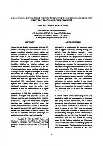
TRANSFORMATION OF WORKFLOW SPECIFICATIONS INTO G-DEVS MODELS 3.1. Local Coupled Models and Simulators G-DEVS « flattened » We based the environment on the Generalized Discrete EVent System Specification (G-DEVS) formalism [4]. It defines behavioural (atomic) models and, by hierarchical composition, structural (coupled) models (e.g. Figure 1 left hand).
1086
SCSC 2007
The concept of abstract simulator used by G-DEVS is based on [12] to define the simulation semantics of the formalism. The architecture of the simulator is derived from the hierarchical model structure as illustrated in Figure 1 right hand. Root Coordinator
Coupled Model A
Coordinator A
Coupled Model B
Atomic Model B1
Coupled Model C
Atomic Model C1
Coordinator B
Coupled Model D
Atomic Model D1
Coordinator C
Simulator B1
Simulator C1
Atomic Model D2
Coordinator D
Simulator D1
Simulator D2
Figure 1. DEVS G-DEVS hierarchical modeling and simulation structure The processors involved in a hierarchical simulation are Simulators, which insures the simulation of the atomic models, Coordinators, which insures the routing of messages between coupled models, and the Root Coordinator, which insures the global management of the simulation (e.g. Figure 1. a, without considering crosses out). The simulation runs by exchanging specific messages (corresponding to different kind of events) between the different processors. The simulator for G-DEVS models is similar to DEVS in its structure. From the hierarchical structure of abstract simulation defined by [12], we propose a hierarchical “compact” structure for the PIOVRA G-DEVS / HLA Environment. We based our specification on the works proposed by [7] with the aim of decreasing the local exchange of messages between the coordinators and the simulators. We reduce the classical GDEVS hierarchical structure [2] of intermediate Coordinators between the Root Coordinator and Simulators, at two hierarchical levels in our G-DEVS simulation structure. Thus, components remaining locally are a Local Coordinator (LC) and a set of atomic Simulators linked as direct successors (named LCS). The example Figure 2 right illustrates the LCS groups. For more details on Flattening techniques, please refer to [5], [7] and [9].
Then, because the various models can be executed on distant computers, we require a technique to interconnect distributed models. 4.
DISTRIBUTED SIMULATION COMPONENTS Our goal is to obtain a distributed simulation environment. To achieve this objective, several LCS groups, defined previously, must intercommunicate to obtain a global distributed simulation (e.g. Figure 3 Computer 2 and 3). For that purpose, it is necessary to manage messages exchanged between the distributed components. According to classical Distributed Computers hardware platform [3], the entities involved in a generic distributed simulation are described in Figure 3, we assumed that the different computers will be interconnected thanks to an interconnection network. The LC manipulates local events regarding its local Logical Time and manages its local simulators. In the case of integrating this local coordinator in a distributed simulation, this component will also have to manage the events resulting from other distant LCS group. To achieve the global synchronization of the simulation, a Distributed Root Coordinator (DRC) needs to be added. DRC corresponds in the example Figure 3 to group Computer 1. This DRC is designed for routing the events exchanged between the LCS groups; DRC has also to synchronize the sending-reception of these events by respecting the causality of the events treatment. DRC uses an event list containing events exchanged in the global simulation and a set of tables describing the coupling relations between the distant coupled models (EICList, EOCList, ICList). The distant LCSs communicate by events passing trough the DRC. On receiving an event from a LC, DRC transforms it regarding to coupling relations from output to input events and inserts it in its EventList. Then, when a LC asks for event pending to be delivered, the DRC delivers it regarding to Synchronization imperatives in order to respect causality. Computer 1 Distributed Root Coordinator
Root Coordinator
Computer 2
Computer 3
Local Coordinator ABCD
Coordinator A
Coordinator AB Coordinator B
Simulator B1
Coordinator C
Simulator C1
Simulator B1
Simulator C1
Simulator D1
Simulator D2
Simulator C1
Simulator D1
Simulator D2
Figure 3. Distributed simulation structure
Simulator D2
Figure 2. “Flattening” hierarchical simulation structure
SCSC 2007
Simulator B1
Coordinator D
Simulator D1
Coordinator ACD
These modeling and simulation components presented above will be detailed in the next section of this document.
1087
ISBN # 1-56555-316-0
5. DETAILED ENVIRONMENT SPECIFICATION 5.1. Data Model We define UML class diagrams to describe the data structure of the environment by showing the environment classes and the relationships between them.
1..* InfluentPortList
1..*
-List : List InfluentPort
1 -name : string -type : string -parentName : string -InfluencedPortList : InfluencedPortList
1
1 0..1
LSIS_DME_Atomic_Model
1..* phases -name : string -timeLife : int -graphicalData : object
In UML, a class is represented by a box with the name of the class written inside it. A compartment below the class name shows the classes attributes: • Variables (prefixed with -) • Functions of the class (prefixed with +). Each attribute is described with at least its name, and optionally with its type, initial value, and other properties.
1
-name : string -phases : object -graphicalData : object -inputPort : InfluentPort -outputPort : InfluentPort -OtherStateVariablesSet : object -eventOrder : object +externelTransitionFunction() +internalTransitionFunction() +confluentTransitionFunction() +outputFunction() +timeLifeFunction()
LSIS_DME_Coupled_Model
0..*
1
0..1
0..*
InfluencedPortList -List : List 0..*
0..*
1..*
0..* 1
0..*
-name : string -hierarchicalLevel : int -inputPort : InfluencedPort -outputPort : InfluentPort -includedModelWithHierarchyList : includedModel -influentPortListWithHierarchy : InfluentPortList -includedModelWithoutHierarchyList : includedModel -nonHierarchicalInfluentPortList : InfluentPortList -graphicalData : object
InfluencedPort
1
-name : string -type : string -parentName : string
1
0..* includedModel -List : List
1
Figure 4. G-DEVS Atomic and Coupled Data Model
We use two types of logical connections on the class diagrams of this document: • Generalization-Specialization A “solid line with a large hollow triangle” used to connect lines between two classes denotes the generalization (or inheritance) relationship. • Association A direct line between two classes denotes the association relationship; it indicates that (at least) one of the two related classes refers to the other. This association relationship is also known as the “has a” relationship.
Simulator and Local Coordinator Data Model We separate the modelling part from the simulation part as recommended in [12]. Figure 5 class diagram represents the local coordinator structure; it contains in particular the lists used to handle events and the coupling relations acquired from the model definition. List
InfluentPort -name : string -type : string -parentName : string -InfluencedPortList : InfluencedPortList
1
1 1
A notation at each end of the association relationship conveys cardinality/multiplicity of each class by indicating the multiplicity of instances of that entity (the number of objects that participate in the association). Common multiplicities are: • 0..1 No instances, or one instance • 1 Exactly one instance • 0..* or * Zero or more instances • 1..* One or more instances G-DEVS Atomic and Coupled Data Model The class diagram depicted in Figure 4 presents the data used to define G-DEVS atomic model and a coupled model. In the atomic description, we present the state variables involved in particular the phase use to de-scribe graphical models. We define also an attribute to define the order of the event that can be treated by the model. In the coupled models, we define two coexistent structures, the first is the hierarchical structure representation of the model (used in the modular modeling) and the nonhierarchical equivalent structure (used in the simulation for performance purpose as described in § 2.1).
ISBN # 1-56555-316-0
-Tete -Nb Element +Increment-NbElement() +Decrement-NbElement() +Reset-NbElement() +EmptyList() +SearchElement() +InsertElement() +SuppressElement()
1..*
InfluencedPortList
DistributedInfluentPortListWithoutHierarchy
-List : object
-PortList : List
0..*
1
GlobalEventList
GlobalWaitList
GlobalStopList
-EventList : List -tn +Classify with priority() +Get first Message Timestamp()
-EventList : List -tn +Classify with priority() +Get first Message Timestamp()
-EventList : List -tn
1 1
1..*
0..*
1
0..*
0..*
1 1
InfluencedPort -name : string -type : string -parentName : string
Distributed_Root_Coordinator
1
-GlobalEqList : List -GlobalWaitList : List -GlobalStopList : List -DistributedlInfluentPortListWithoutHierarchy : List -GlobalLocalCoordinatorTimeList -GlobalLookaheadList -LBTS -LocalCoordinatorList : List -LookaheadList +JoinFederationRequest() +GetInfluencedBy() +initialiseXmessage () +When receive Back message packet() +Extract Dmessage() +Get-Influenced-By() +Send selected message() +GetInfluencerOf() +SendAutorisation() +Compute LBTS() +Extract Ymessage() +Extract Lookahead()
1
Event -messageType : char -receiver : string -eventTimeStamp : float -concernedPort : string -EventValue : List
1
1
1
Figure 5. Simulator and Local Coordinator Data Model 5.2. Function model The functions are presented in the form of pseudo code algorithms. These algorithms detail the functions of the component involved in the simulation: Root Coordinator, Local Coordinator and Simulator. In this paper, we detail the Function of LC and S in Figure 6 and Figure 7. DRC functions are not detailed because, in the implementation, HLA RTI will handle these features. Details of RTI functions can be found in [6]. The comments are noted with the prefix ‘//’, the classical control structure are noted in bold in the pseudo code. The main function involved into the environment, are presented by underlined words. The data used referred to the class diagram presented above.
1088
SCSC 2007
Eq Lq Wq LBTS Event WaitList StopList EICList
// queue to store the Event List // queue to store the lookahead of coordinators Ports // queue to store the List of coordinators waiting // value of lower bound time stamp // Event message structure (Message Type, addressee/transmitter, event timestamp, concerned Port, Event Value) // queue to store the Event sent // queue to store the Event treated // queue to store the list of couple (Root Coord, Port) (Coord, Port) that express the coupling between the global model Input Port and the local Model Input Port // queue to store the list of couple (Coord, Port) (Root Coord, Port) that express the coupling between the local Model Output Port and the global model Output Port // queue to store the list of couple (CoordA, PortA) (CoordB, PortB) that express the coupling between a local Model Output Port and another local model Intput Port value in YMessage and Xmessage is a list of value for G-DEVS
EOCList ICList Value
When receive Ymessage (‘y’, Children_Coordinator, t, Children_Coordinator_Port, Value) Get-Internal-Influenced-By (Children_Coordinator, Children_Coordinator_Port) for each children influenced by output // According to ICList Add Xmessage (‘x’, Children_Coordinator_Influenced, t, InfluencedPort, Value) in Eq // According to priority def Get-External-Influenced-By (Children_Coordinator, Children_Coordinator_Port) Print Output Event (Message) When receive Dmessage (‘d’, Children_Coordinator, t, - , Value) Add to StopList // check for Message in process in WaitList if (Message also WaitList) then remove this message from WaitList and StopList Print Event (Message also WaitList) done else routing error When receive Lookahead message (‘l’, Children_Coordinator, t, OutputPort, Lookahead Value) add Lookahead (Children_Coordinator, OutputPort, Lookahead Value) in Lq Get-Internal-Influenced-By (Children_Coordinator, Children_Coordinator_Port) if ((Children_Coordinator influences Another_Children_Coordinator) & (Another_Children_Coordinator, vance_Requested_Time) is in Wq // a coordinator influenced is waiting for Next-Event grant then Remove Another_Children_Coordinator from queue Wq Compute-LBTS (Another_Children_Coordinator, InfluencedPort) // using the lookahead min of the influences of the model that is simulated by Another_Children_Coordinator
InputPort,
LocalTime,
if (there is a Message for Another_Children_Coordinator in Eq with timestamp t < LBTS & t < Advance_Requested_Time) then Add in WaitList (Message) send selected (Message) & mark it “send” // as an answer to the request else if (Advance_Requested_Time < LBTS) then Add in WaitList Autorisation (Advance_Requested_Time) & mark it “send” send Autorisation (Advance_Requested_Time) // as an answer to the request else if ((Advance_Requested_Time >= LBTS) or (Advance_Requested_Time == null)) & (LocalTime =! LBTS) then Add in WaitList nullmessage(“null”, coordinator, LBTS, InputPort,-) send nullmessage(“null”, coordinator, LBTS, InputPort,-) & mark it “send” // as an answer to the request else if (LocalTime == LBTS) then add (Another_Children_Coordinator, LocalTime, Advance_Requested_Time) in Wq When receive for Next-Event-Request (Children_Coordinator, InfluencedPort, LocalTime, Advance_Requested_Time) Get-Internal-Influencer-Of (Children_Coordinator, InfluencedPort) Compute-LBTS (Children_Coordinator, InfluencedPort) // using the lookahead min of the influences of the model that is simulated by Children_Coordinator if (there is a Message for Children_Coordinator in Eq with timestamp t < LBTS & t < Advance_Requested_Time) then Add in WaitList (Message) & mark it “send” send selected(Message) // as an answer to the request else if (Advance_Requested_Time < LBTS) then Add in WaitList Autorisation (Advance_Requested_Time) & mark it “send” send Autorisation (Advance_Requested_Time) // as an answer to the request else if ((Advance_Requested_Time >= LBTS) or (Advance_Requested_Time == null)) & (LocalTime =! LBTS) then Add in WaitList nullmessage(“null”, coordinator, LBTS, InputPort,-) & mark it “send send nullmessage(“null”, coordinator, LBTS, InputPort,-)” // as an answer to the request else if (LocalTime == LBTS) then add (Children_Coordinator, LocalTime, Advance_Requested_Time) in Wq When receive for Join-Federation-Request (Coordinator, EIC, EOC, IC) // A local Coordinator ask to join a federation. // EIC List of couple of External Input Coupling // EOC List of couple of External Output Coupling // IC List of couple Internal Coupling Add EIC couple ((Root Coord, Port) (Coord, Port)) in EICList Add EIC couple ((Coord, Port) (Root Coord, Port)) in EOCList Add EIC couple ((CoordA, PortA) (CoordB, PortB)) in ICList B = Get-Internal-Influenced-By (A) A = Get-External-Influenced-By (C) A = Get-Internal-Influencer-Of (B) B = Get-External-Influencer-Of (C)
// // // // // // // //
According to the couple ((CoordA, PortA) (CoordB, PortB)) in the IC List, the Output PortA influences the Input PortB According to the couple ((CoordC, PortC) (CoordA, PortA)) in the EIC List, A is an internal model of C and the Intput PortC influences the Input PortA According to the couple ((CoordA, PortA) (CoordB, PortB)) in the IC List, the Intput PortB is influenced by the Output PortA According to the couple ((CoordB, PortB) (CoordC, PortC)) in the EOC List, B is an internal model of C and the Outtput PortB influences the Output PortC
Compute-LBTS (Children_Coordinator, InfluencedPort) LBTS = min of (lookahead in Lq that influences InfluencedPort of Children_Coordinator) // sub-models influencer are defined according to coupling store in IC List.
Figure 6. G-DEVS Conservative-Local-Coordinator
SCSC 2007
1089
ISBN # 1-56555-316-0
Ad-
Parent tl tn G-DEVS
// // // //
parent coordinator time of last event time of next event associated model with total state (s, e)
When receive Imessage (‘i’, Simulator, t, - , - ) tl = t – e tn = tl + ta(s) compute lookahead send Lookahead message (‘l’, Simulator, t, OutputPort, Lookahead Value) to parent send Dmessage (‘d’, Simulator, t, - , Value) to parent When receive *message (‘*’, Simulator, t, - , - ) at time t if (t= tn) then y = λ (s) send Ymessage (y, t) to parent coordinator s = δint (s) tl = t tn = tl + ta(s) compute lookahead send Lookahead message (‘l’, Simulator, t, OutputPort, Lookahead Value) to parent send Dmessage (‘d’, Simulator, t, - , Value) to parent else error : bad synchronization When receive Xmessage (‘x’, Simulator, t, InfluencedPort, x) if (tl1 lines leaving. These denote join/fork, respectively. Overall Behavioral model The overall state diagram (Figure 8) introduces the main objectives of the components, the objective of the LC is treating events and the DRC is designed to route the event
ISBN # 1-56555-316-0
exchanged between the distributed components of the global simulation. Local processing of events Request to process an event Send an event Send the Lookhead
Distribute coordination of events Answer
Figure 8. Overall Behavioral model G-DEVS Conservative-Distributed-Root-Coordinator Figure 9 diagram describes the treatments of the Conservative-Distributed-Root-Coordinator. We distinguish two main functions. The first one is defined to receive message emitted by Local components. The second is defined to answer to components calls to advance and treat their local messages. In function of information, notably LBTS (Lower Bound on Time Stamp = min of Lookahead of influencers), from the different components, this component answers by granting calls or by delivering events time stamped earlier than the grant. In some cases, it delivers a null massage in order to avoid dead lock as described in [1].
1090
SCSC 2007
Ditribute root coordinates events [Reception Request autorizaation] Tlocal
TSuivantGlobal
TSuivantLocal
LBTS
[Event to Local Coordinator in event list root coordinator with TGlobalNext < TLocalNext && TGlobalNext < LBTS]
Tlocal
Compute the LBTS
TSuivantLocal
LBTS
If coordinator waiting then take out from WaitList the coordinators waiting Compute the minimum of all Lookhead of influencers
[No event to Local Coordinator in ListEvent of the root coordinator && TLocalNexet < LBTS] Send event of EventList of Root Coordinator to Local Coordinator Add LBTS in message Add event in WaitList TL = TSGlobalNext tn = t of the next event of EventList Send the event to the applicant Delete the event from EventList of Root Coordinator
Tlocal
LBTS
Tlocal
LBTS
TSuivantLocal
[No event for Local Coordinator in EventList of Root Coordinator && ((TLocalNext > LBTS) or ((TLocalNext == empty) and (TLocal < LBTS))) ]
[Lookhead concened a cooridnator waiting] [(No event for Local Coordinator in EventList of Root Coordinator) and ((LBTS < TLocalNext)and (TLocal == LBTS)or ((TLocalNext == empty) and (TLoacal == LBTS)) ] Tlocal
Allow to Local Coordinator to select the next event of ot its EventList LBTS Tlocal
Add LBTS in Autorization message Add Autorization message to WaitList Send Autorization message to Applicant
TSuivantLocal
LBTS
Send Null-message to Local Coordinator Add Null-Message to WaitList Add Null-Message to Applicant
Change the request of Local Coordinator to Wait / Dmessage / Dmessage
Add Coordinator to WaitList Coordinators waiting
/ Dmessage
Take into account incoming events [WaitList == StopList] Updater lookahead from port and Coordinator local emiter If Dmessage then add to StopList the sender of the Dmessage If Ymessage then transform to Xmessage Si Ymessage to the concerned influenced Add Xmessage to EventList of Root Coordinator
Figure 9. G-DEVS Conservative-Distributed-Root-Coordinator G-DEVS ConservativeDistributedLocalCoordinator After being registered at the DRC, the LC manages a local ordered event list containing local events to be treated. It calls the DRC to ask for a grant to treat its next message regarding its local time as described in Figure 10.
wait for acquittal message from this simulator. When receiving an acquittal message and an eventual output messages from the simulator it sends to the DRC this eventual message. Finally, it starts again loop turn. Processing of Received Event from Parent
Local processing of events [subscribed Coordinator in the synchronisation module]
Dstribution of Received Event
Get the date of the next event from the local event list
axk Compute the LBTS to Distributed Root Coordinator
Autorization request of processing the next event of the local event list
Local Simulator
from the Dstributed Root coordinator answer
[Received Message [Receivet Message that holds an autorization Message de reponse that holds an event reçu contient une autorisation] ]
Process of the received event from parent
Figure 11. Conservative-Distributed-LocalCoordinator
Processing of the first event in the local event list
to take into account the event at Root Coordinator level
Figure 10. Conservative-Distributed-LocalCoordinator When the LC receives the grant or the message from the DRC it transmits it to the local Simulator influenced and
SCSC 2007
We detail in Figure 11 the process of sending a message received from the DRC to the simulator concerned. Note that it can be also possible to receive, from the DRC, a null message to avoid deadlock situations. Sending a local event is detailed in Figure 12; the event is suppressed from the event list and sent to child Simulator. This model describes the emission to the simulator concerned and the reception of the message of treatment acquirement corresponding.
1091
ISBN # 1-56555-316-0
From Simulator
Vers simulateur
Distribution of *message Supress the Event that cooresponds to message of EventList with same timestamp Add this event to WaitList Send this message to WaitList (noetd sent) TL = T TN = T first event of EventList / *message autorization Waiting answer of Simulator
Waiting the reception of authorization
[Received Ymessage & Dmessage ] Distribution of Xmessage [Local influenced]
Transform Ymessage to Xmessage Update in WaitList Xmessage for every concerned processors Send first message of WaitList (noted sent) TN =T first event of EventList TL = T Xmessage
[Message of end of simulation]
[No Local influenced]
Distribution autres messages WaitList Envoyer prochain message WaitList (non noté envoyé) Distribution of Ymessage and Dmessage [WaitLMist != StopList] Suppress the equivalent message from WaitList and StopList Update EventList with the new *messages Update StopList and WaitList Send Dmessge to the successor Send Ymessage TL = T TN = T first event of EventList
Reception of Dmessage
[WaitList == StopList]
Update EventList with the new *message Add to StopList the sender of Dmessage
Waiting answer of Simulator
Reception of Lookahead message
Processing first event of Local EventList
Update Lookahead List Compute Lookahead = min Lookahead of successeurs of LookaheadList by output port Send Lookahead
From Simulator
Figure 12. Local Event Processing G-DEVS Conservative-Local-Simulator Figure 13 model addresses the treatment of the different kind of events by a Simulator. Notably, the notion of null message has been added to classical events event took into account in the sequential version introduced by [12]. This message is used to avoid deadlock in conservative distributed time management.
uted simulation, in order not to another charge in the project. Finally, others HLA compliant software can be added without recoding. A first approach, presented in [11], of DEVS coordinators integration in an architecture respecting the HLA standard. They defined a local coupled model as a HLA federate whose coordinator of higher level will have responsibility to communicate with the federate Time Manager. We choose to follow [11] mapping of LCS into HLA federates, but we do not use the Time Management federate and map the DRC, defined in this specification document, directly into the RTI because this specification of interface (RTI) proposes services which enclose those defined in our Distributed Root Coordinator. Indeed, the RTI manages Time Stamped messages and synchronizes the federates. The “global distributed” model (i.e. the federation) is constituted by creating a communication link between federates. Figure 14 illustrates this HLA mapping according to RTI Specification of [6]. Computer 1 Central RTI Component
Interconnexion Network
Computer 2 Local Simulator
Computer 3
To level Distribution of received event
Processing *message
Processing Nullmessage
[Received Message == *Message and T = TN ]
[Received Message == Nullmessage and TL