has been very successful from a medical point of view and its second edition .... is DICOM, quite frequently various general-purpose graphical formats (such as ...
*Revised Manuscript (unmarked) Click here to view linked References
1 2 3 4 5 6 7 8 9 10 11 12 13 14 15 16 17 18 19 20 21 22 23 24 25 26 27 28 29 30 31 32 33 34 35 36 37 38 39 40 41 42 43 44 45 46 47 48 49 50 51 52 53 54 55 56 57 58 59 60 61 62 63 64 65
Holistic Approach to Design and Implementation of a Medical Teleconsultation Workspace Łukasz Czekierda, Filip Malawski, Przemysław Wyszkowski {luke, fmal, pw}@agh.edu.pl Department of Computer Science, AGH University of Science and Technology ul. Kawiory 21, 31-059 Kraków, POLAND tel: +48 12 3283369, fax: +48 12 6175172
Graphical abstract
Keywords: telemedicine, teleconsultation, collaboration, SOA, VO, teleradiology
Highlights: ●
In-depth requirements analysis for medical teleconsultation systems
●
A holistic model for medical teleconsultation systems is proposed
●
Several areas of application: typical remote consultations, research and education
●
Takes advantage of Service Oriented Architecture and Virtual Organizations paradigms
●
Addressed aspects: security, isolation, deployment, real-time collaboration and more
1
1 2 3 4 5 6 7 8 9 10 11 12 13 14 15 16 17 18 19 20 21 22 23 24 25 26 27 28 29 30 31 32 33 34 35 36 37 38 39 40 41 42 43 44 45 46 47 48 49 50 51 52 53 54 55 56 57 58 59 60 61 62 63 64 65
Abstract While there are many state-of-the-art approaches to introducing telemedical services in the area of medical imaging, it is hard to point to studies which would address all relevant aspects in a complete and comprehensive manner. In this paper we describe our approach to design and implementation of a universal platform for imaging medicine which is based on our longstanding experience in this area. We claim it is holistic, because, contrary to most of the available studies it addresses all aspects related to creation and utilization of a medical teleconsultation workspace.
We present an extensive analysis of requirements, including possible usage scenarios, user needs, organizational and security issues and infrastructure components. We enumerate and analyze multiple usage scenarios related to medical imaging data in treatment, research and educational applications – with typical teleconsultations treated as just one of many possible options. Certain phases common to all these scenarios have been identified, with the resulting classification distinguishing several modes of operation (local vs. remote, collaborative vs. noninteractive etc.).
On this basis we propose a system architecture which addresses all of the identified requirements, applying two key concepts: Service Oriented Architecture (SOA) and Virtual Organizations (VO). The SOA paradigm allows us to decompose the functionality of the system into several distinct building blocks, ensuring flexibility and reliability. The VO paradigm defines the cooperation model for all participating healthcare institutions. Our approach is validated by an ICT platform called TeleDICOM II which implements the proposed architecture. All of its main elements are described in detail and cross-checked against the listed requirements. A case study presents the role and usage of the platform in a specific scenario. Finally, our platform is compared with similar systems described in to-date studies and available on the market.
1. Introduction Continuous progress in medicine has been ongoing for many years. Among its signs are rapid improvements in the accessibility of medical imaging equipment and, at the same time, increasing accessibility of imaging procedures. According to [1] over 100 million radiographs, 26 million MRIs and 30 million CT/PET examinations are performed annually. On the other hand, the number of medical experts able to properly analyze such scans is growing at a much slower pace. To work efficiently, hospitals are often organized into larger structures, with various levels 2
1 2 3 4 5 6 7 8 9 10 11 12 13 14 15 16 17 18 19 20 21 22 23 24 25 26 27 28 29 30 31 32 33 34 35 36 37 38 39 40 41 42 43 44 45 46 47 48 49 50 51 52 53 54 55 56 57 58 59 60 61 62 63 64 65
of reference based on their excellence in specific areas. Routine cases are usually treated at low-reference medical centers while more difficult ones require referral to high-reference institutions.
Teleconsultation applications play an important and well established role in this ecosystem, allowing experts from leading medical centers to remotely diagnose complex cases and suggest proper treatment options. ICT progress has enabled such systems to be applied in everyday medical practice in many countries. Most of these systems operate under a fairly simple rule – their role is to transfer digital medical documentation from one medical center to another and return a diagnosis or further treatment suggestions. Such systems generally allow users to remotely access and analyze medical images and their associated documentation. Due to lack of interactivity this cooperation model does not accurately mimic a real-life medical council. Moreover, simple features are insufficient when complex or atypical cases need to be handled.
Performing effective remote medical imaging consultations remains a real challenge. For over ten years we have been popularizing the idea of collaborative remote medical consultations (an example of so-called Computer-Supported Cooperative Work (CSCW) systems) where many users concurrently participating in a consultation session are able to share a view of the session as fully as possible. In our opinion this approach mirrors the traditional consultation process performed locally in the most accurate way. Moreover, it also creates the basis for development of new, more sophisticated applications.
Paul’s interesting paper [2] analyzes teleconsultation systems from the standpoint of knowledge management. The author introduces several classes, ordered by growing complexity: systems dedicated to a) knowledge transfer, b) discovery, and c) creation. Typical teleconsultations rely on simple knowledge transfer. An example of the knowledge discovery class is provided by the formulation of a new diagnosis. The rarest cases involve knowledge creation – e.g. invention of a new disease treatment protocol. We believe that challenging scenarios require appropriate telemedical infrastructure and that collaborative teleconsultation systems provide the proper means to tackle them in an effective manner. Even though a convenient way of communication is provided, in many cases the cooperation flexibility is indispensable. Statically deployed structures (spokes connected to a single hub – usually a university-affiliated medical research center) with applications running on predeployed machines are not able to cope with
3
1 2 3 4 5 6 7 8 9 10 11 12 13 14 15 16 17 18 19 20 21 22 23 24 25 26 27 28 29 30 31 32 33 34 35 36 37 38 39 40 41 42 43 44 45 46 47 48 49 50 51 52 53 54 55 56 57 58 59 60 61 62 63 64 65
requirements of urgent and rare cases which call for dynamic on-demand creation of teleconsultation services, possibly with an international scope.
In this paper we describe our approach to the design and implementation of a universal system for imaging medicine. We believe that our proposals are justified by our longstanding experience with development, deployment and monitoring of various scenarios in the TeleDICOM I [3] interactive teleconsultation system. The presented concepts are embodied by TeleDICOM II, the successor of TeleDICOM I. We consider various scenarios related to medical scans: individual assessment, multiparty non-interactive and interactive remote consultations for diagnostic and research purposes, efficient handling of medical conferences and workshops, as well as teaching and training – thus satisfying all three conditions listed by Paul.
Our aim was to design a modern, flexible and extensible telemedical platform, which could be easily adjusted to the needs of specific deployments - to achieve these goals our system design follows the Service Oriented Architecture (SOA) principles. Potential users of the platform include doctors, medical students and researchers, as well as small, medium and large healthcare centers. Cooperation is performed in a secure environment called a Virtual Organization (VO) – these can be created on demand, taking into account specific needs of the target community, and be isolated from other VOs.
Practical implementation of such a system is technologically challenging. Interactive communication is characterized by strict Quality of Service (QoS) requirements, especially when conducted between multiple participants in a heterogeneous network environment. Other important aspects include scalability, security as well as construction of a universal and userfriendly Graphical User Interface (GUI), to mention just a few.
As the merit of our approach we attempt to address all the issues related to creation of medical teleconsultation workspace in a comprehensive way. We take into account a very wide range of usage scenarios - adoption of the collaborative cooperation model makes it possible to perform virtually any activity related to medical imaging data independently or in groupware mode. We propose a sophisticated, flexible and scalable architecture and discuss implementation issues multi-dimensionally. Therefore we can claim that our approach is holistic.
4
1 2 3 4 5 6 7 8 9 10 11 12 13 14 15 16 17 18 19 20 21 22 23 24 25 26 27 28 29 30 31 32 33 34 35 36 37 38 39 40 41 42 43 44 45 46 47 48 49 50 51 52 53 54 55 56 57 58 59 60 61 62 63 64 65
The structure of this paper is as follows. The state of the art in the target domain is presented in Section 2, alongside our to-date experience. In Section 3 we discuss our holistic telemedical workspace model. Section 4 describes the architecture of TeleDICOM II which satisfies most of the stated requirements. Section 5 presents selected implementation aspects. Case study in Section 6 describes typical scenarios of TeleDICOM II utilization. Section 7 ends the article with conclusions and a description of future works.
2. Background 2.1 State of the art Many medical teleconsultation systems have been created over the years. As described in detail in the following sections, several aspects have to be considered when designing such a system. We propose to divide these aspects into four categories, each of which will be thoroughly discussed later on in this paper: a) application-level usage scenarios, b) user requirements, c) organizational issues, and d) infrastructure.
In the scope of application-level usage scenarios the main criterion is the communication model. While many systems offer simple asynchronous, store-and-forward capabilities [4-14] more sophisticated solutions enable synchronous consultations based on audio, video and chat channels [15-24]. Advanced systems offer interactive tools such as whiteboards, telepointers and (in fewer cases) synchronized annotations and image processing capabilities [25-37]. Our solution enables full view synchronization including an extensible measurement toolset, and provides multi-access control with fine granularity (down to the level of single objects and operations).
The second relevant aspect in this category is the purpose of the teleconsultation session: diagnostics, research or education. While diagnostics are the primary focus of most of the presented systems, research and education are rarely taken into account and supported in an enhanced manner [4, 10, 20, 38]. Our system provides multiple cooperation modes suitable for each of these scenarios.
User requirements include (among others) image transformations, annotations, measurement tools and data presentation tools. Basic image transformations are available in most systems. Annotations and measurement tools are common in asynchronous systems [8, 11, 16, 29, 30]
5
1 2 3 4 5 6 7 8 9 10 11 12 13 14 15 16 17 18 19 20 21 22 23 24 25 26 27 28 29 30 31 32 33 34 35 36 37 38 39 40 41 42 43 44 45 46 47 48 49 50 51 52 53 54 55 56 57 58 59 60 61 62 63 64 65
and less common in interactive synchronous systems [36, 37]. Many solutions focus on one area of medicine, providing specific tools only for one field, e.g. teledermatology [11] or telecardiology [12]. The issue of extensibility and adaptability is rarely addressed [39, 40]. Our solution provides a wide range of synchronized tools for image transformations, annotations and measurements which can be easily extended (including synchronization) in order to adapt the system to any medical domain. We also support data presentation by enabling multiple views and sorting features. Finally, we provide image processing optimization – an important aspect of interactive scenarios which is seldom taken into account [41].
Organizational issues are related to formal aspects of creating a cooperation workspace which spans multiple healthcare providers. These issues are conveniently omitted in most papers, with few exceptions in some of the more recent works [42-47]. Here, we identify several aspects, including multiple, isolated cooperation networks, resource allocation, security, fine-grained user permissions and non-repudiation. In order to address these issues we employ the concept of Virtual Organizations (VO), which is only acknowledged in a handful of telemedicine-related publications [42, 47]. Our solution facilitates creation of new VOs and enables convenient participation in multiple VOs.
As stated in our previous papers [48, 49], proper infrastructure is one of the key prerequisites of an advanced teleconsultation scenario. Simple systems adapt existing telecommunication technologies, such as telephone, e-mail, FTP servers and clients, videoconferencing software or general teleconsultation software, e.g. Microsoft NetMeeting [8, 17, 19, 22, 29, 34]. Advanced systems provide dedicated software which handles more complex tasks, e.g. medical image annotations, data delivery or session management [11, 16, 31, 36, 37]. Our approach assumes division of the system into several subsystems, responsible for different aspects of cooperation. We employ the Service Oriented Architecture (SOA) paradigm in order to take advantage of the flexibility of dynamic service setup, with replication and federalization enhancing the system’s QoS as well as its resilience. SOA has previously been utilized in telemonitoring [5052], sharing of medical information and knowledge [53-56] and several non-interactive teleconsultation systems [57, 58]. Our solution constitutes a novel approach to employing the SOA paradigm in an interactive, fully synchronized teleconsultation scenario.
While the aforementioned systems address various issues, none of them constitutes a complete, unified solution. The holistic nature of our approach is a consequence of addressing
6
1 2 3 4 5 6 7 8 9 10 11 12 13 14 15 16 17 18 19 20 21 22 23 24 25 26 27 28 29 30 31 32 33 34 35 36 37 38 39 40 41 42 43 44 45 46 47 48 49 50 51 52 53 54 55 56 57 58 59 60 61 62 63 64 65
all of the described aspects. Furthermore, our solution is based on almost ten years’ worth of experience in development and practical usage of our previous teleconsultation system – TeleDICOM I. We believe that user feedback, the importance of which is emphasized in several publications [35, 59-62], is the key to developing a robust teleconsultation platform.
2.2 TeleDICOM I As stated in the previous section, any attempt to define a holistic approach to realization of a teleconsultation workspace for imaging medicine requires not only a thorough study of the discussed area but also practical experience. In our case, the necessary experience stems from our work on designing, developing, deploying and supervising operation of TeleDICOM I – a system for interactive consultations in imaging medicine. The following section provides a brief introduction to the system and enumerates its most important usage scenarios (also discussed in [48, 49]).
Unlike many existing solutions deployed into production around the world TeleDICOM I is collaborative, i.e. enables users who participate in a teleconsultation session to share a common view of the session as fully as possible, mirroring a local consultation process. The cooperation model is outlined below: 1. Medical imaging data, uploaded and annotated by the creator of the so-called consultation session, is delivered to a central node responsible for its storage and provisioning to other users for analysis. The need to transfer files to local computers follows from the requirement of preserving original, diagnostic data quality, which cannot be satisfied if a remote desktop or similar solution is used. 2. The course of the consultation depends on the desired session type. In the noninteractive mode only a single user (consultant) analyzes the data using a board and specialized manipulation and measurement tools. In an interactive session all participants share a common view of the session: actions performed by any user are propagated to all other users. Moreover, users are able to communicate interactively using a voice channel. Data analysis thus becomes a collaborative process. 3. If the analysis ends with conclusions, these can be provided by the consultant(s). The system has been used in a number of applications, starting with a typical teleconsultation scenario for which it was originally implemented: ●
Since 2006 TeleDICOM I has been employed as a regular and emergency hospital service in two distinct teleconsultation networks. In such a network one hospital plays
7
1 2 3 4 5 6 7 8 9 10 11 12 13 14 15 16 17 18 19 20 21 22 23 24 25 26 27 28 29 30 31 32 33 34 35 36 37 38 39 40 41 42 43 44 45 46 47 48 49 50 51 52 53 54 55 56 57 58 59 60 61 62 63 64 65
the role of a hub while other institutions (with a lower level of reference) deliver examinations to be consulted. Overall, more than 13,000 cases were diagnosed using TeleDICOM I, currently reaching the level of 3,500 cases per year. ●
Since 2007 TeleDICOM I has been used at the Jagiellonian University Medical College in Krakow for teaching purposes. A group of students (10-15 people) gather in a laboratory and participate in a common collaborative session, learning how to diagnose difficult cases on the basis of consultations prepared by teachers and under their supervision.
●
Since 2007 TeleDICOM I has been used as a support tool at numerous medical conferences and workshops. Several open training sessions for cardiologists from around Poland have also been organized.
●
Starting in 2011 TeleDICOM I has been used for online meetings between experts participating in the Rare Cardiovascular Diseases Project1 coordinated by the John Paul II Hospital in Kraków. During such meetings experts from Kraków, Berlin, Kaunas and Riga are able to present rare cases and discuss proper treatment options. The project has been very successful from a medical point of view and its second edition started in 2013, with participation of additional Polish and international medical centers.
3. System concept and key requirements Each successive deployment of the system produced valuable feedback which allowed us to gradually improve TeleDICOM I. This feedback is presented in detail in [48]. The Rare Cardiovascular Diseases Project meetings were particularly productive since the potential of the interactive mode was fully utilized in real-life scenarios. Nevertheless, certain limitations of the TeleDICOM I architecture (including centralized location of services, tight coupling of system components and insufficient administrative features) provided the motivation for development of a second version of the system: TeleDICOM II. This approach was seen as preferable to further refinement of the existing application (see: [48]).
The significant experience gathered over the years encouraged us to develop a new, holistic concept for the design and implementation of an interactive teleconsultation workspace.
1
www.crcd.eu
8
1 2 3 4 5 6 7 8 9 10 11 12 13 14 15 16 17 18 19 20 21 22 23 24 25 26 27 28 29 30 31 32 33 34 35 36 37 38 39 40 41 42 43 44 45 46 47 48 49 50 51 52 53 54 55 56 57 58 59 60 61 62 63 64 65
3.1 Application-level usage scenarios At this point it may be useful to enumerate possible usage scenarios related to medical imaging data (supplemented by textual information, whenever necessary). We concentrate on tasks performed by persons familiar with imaging medicine, including medical practitioners (physicians and experts), researchers and medical students (we will jointly refer to these persons as users). We assume that datasets are stored in a digital form and can be processed using computer software. Human-machine cooperation in the scope of medical image processing is mentioned in the following part of this section.
The most obvious and popular scenario involves diagnostics. Medical imaging data describing a single patient is usually subject to complex analysis and reasoning, often carried out in an iterative way, utilizing the knowledge and experience of medical experts. Its result should be a diagnosis, i.e. a statement regarding the patient’s condition, suggested or required therapy, further treatment options, etc. In more complex cases the need for additional information or involvement of other experts may be ascertained.
Quite frequently the goal of imaging data analysis is to obtain generalized insight not necessarily limited to a single patient. We will refer to this as the research scenario. A comparative study involving multiple patients suffering from the same rare disease is a good example. Such a study may require a special toolset, which can differ from those used for ordinary diagnosis. Thus, a requisite feature is easy inclusion of new tools. Quite often research may require real-time cooperation between experts, which calls for collaborative operation options. The third basic usage scenario involves education, with at least two options worth enumerating. The first involves dissemination of expert knowledge representing some area of imaging medicine. The goal of the second is to request an opinion, for example from students based on imaging data provided to them and then to validate its correctness.
All the presented usage scenarios follow the same general template: the available information is analyzed to draw some conclusions. We will call this analysis a consultation process. In general consultation process is defined as the activity of providing professional or expert advice in a particular area. Our understanding of this term is slightly enhanced – we will use it even if the analysis is performed by non-experts, or when a single person analyzes the available data.
9
1 2 3 4 5 6 7 8 9 10 11 12 13 14 15 16 17 18 19 20 21 22 23 24 25 26 27 28 29 30 31 32 33 34 35 36 37 38 39 40 41 42 43 44 45 46 47 48 49 50 51 52 53 54 55 56 57 58 59 60 61 62 63 64 65
Consultation must be preceded by preparatory actions. These comprise identifying appropriate imaging data for analysis, and defining its goal, i.e. the expected result to which the analysis should lead (for example – diagnosis in the first of our three usage scenarios). Analysis should conclude if the goal has been reached or if it cannot be reached for whatever reason. The whole consultation process will thus consist of two phases: preparation (resulting in a consultation dataset creation) and a consultation session, which is the actual activity of medical case assessment.
For completeness’ sake, our discussion needs to take into account two important aspects: the number of participants involved in the consultation process and their location. A single consultation process instance can involve one or more users. Each user can play one of three roles: a creator who prepares imaging data and defines the goal of the analysis, a consultant who performs the analysis and formulates its conclusions (this may also be a student in the education scenario) and an observer who passively observes the consultation process without being able to influence it. Support for the last role is important, since even passive observation of a discussion led by experienced doctors may carry educational value. In the simplest scenario one user performs the entire task by him-/herself. In a more complex scenario imaging data can be prepared by one person and analyzed by a team of collaborating experts with passive participation of students.
An orthogonal view takes into account the spatial distance between persons involved in the consultation process (appropriate technical means should support such an undertaking). For example, imaging data can be prepared at one healthcare institution and diagnosed by experienced medical doctors at another institution. This division into local and remote modes can be extended further: depending on whether real-time collaboration is possible, remote interactive and remote non-interactive modes can be introduced. Generally, a single person is active in the local mode, two in the remote non-interactive mode and two or more in the remote interactive mode (although in each mode any number of observers can locally watch the actions of an active user).
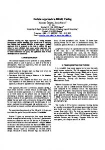
Remote Scenario
Local Non-interactive
Interactive
10
1 2 3 4 5 6 7 8 9 10 11 12 13 14 15 16 17 18 19 20 21 22 23 24 25 26 27 28 29 30 31 32 33 34 35 36 37 38 39 40 41 42 43 44 45 46 47 48 49 50 51 52 53 54 55 56 57 58 59 60 61 62 63 64 65
Diagnostics
Independent analysis
A user’s request is directed
A user’s request is directed to
by the user
to another institution or an
multiple institutions or medical
individual
expert.
experts. This approach is more
usually
appropriate in diagnosing more
sufficient and preferable in
urgent or tougher cases where
routine cases (requiring little
the organizational overhead is
organizational effort).
justified.
Independent analysis
A user’s request is directed
Collaborative discussion in a
by the user
to an expert.
multidisciplinary
This
Research
medical
mode
is
typically,
the
team most
–
efficient
approach in this scenario. Education
Presentation
of
a
A request for some activity
Presentation of cases to one or
case using e.g. a
is submitted to individual
more
remote
projector – similar to users (students) based on
webinar-like
slideshow
prepared input data, with
mode).
presentations
results
(teaching mode)
verification (student mode).
being
subject
users
setup
in
a
(teaching
to
Table 1. Characteristics of “diagnostics”, “research”, and “education” scenarios in the scope of local and remote realization In all three modes preparatory steps have to be undertaken by the session creator. Depending on the specific scenario, analysis can be performed either entirely locally (e.g. presentation of a case in the education scenario), fully remotely (e.g. non-interactive teleconsultation in the diagnostics scenario) or with input from all participants of an interactive session (e.g. collaborative discussion in the research scenario). Even more complex situations can be imagined – for example, the person starting the consultation process may also play the role of a consultant, initiating analysis, which is then extended by other consultants. Each of those issues poses a number of organizational and technical problems which will be further addressed in Subsection 3.3 and next Sections.
While discussing the above scenarios we usually focus on human-to-human interaction, but in some cases the diagnostics and – to some degree – research scenarios can be performed or at least supported by specialized software, transforming interaction into a human-machine process. Medical imaging data is subjected to processing in order to transform it into a different
11
1 2 3 4 5 6 7 8 9 10 11 12 13 14 15 16 17 18 19 20 21 22 23 24 25 26 27 28 29 30 31 32 33 34 35 36 37 38 39 40 41 42 43 44 45 46 47 48 49 50 51 52 53 54 55 56 57 58 59 60 61 62 63 64 65
form or glean some information from it. This process can be performed either locally or remotely, although when the necessary software carries licensing restrictions, is highly complex or requires a special runtime infrastructure, the remote scenario may be preferred.
The presented classification covers all of the previously identified scenarios and thus we claim it is complete. Nevertheless, it cannot be treated as closed and any system implementing the holistic approach should support introduction of new scenarios. Existing medical imaging software typically focuses on supporting only one or a subset of the features mentioned in this section. Our goal is to propose a solution able to support all these activities.
3.2 User requirements In our holistic model the consultation process can be performed entirely locally, or alternatively, analysis may be ceded to remote users (or automata). Moreover, it is possible for analysis to be started by the creator and then carried on by consultants. This calls for a flexible user application structure.
The data The starting point in the creation of a consultation process is to select appropriate data for analysis. The system is expected to process medical imaging data, but the term “medical data” can be somewhat blurry. While the widely-adopted representation standard for medical images is DICOM, quite frequently various general-purpose graphical formats (such as JPEG) are utilized. Non-diagnostic data usually lacks diagnostic quality and does not enable measurements and advanced processing. Nevertheless, in some cases (e.g. when organizing teaching consultation sessions or sessions aimed at exchanging expert knowledge) the use of non-diagnostic images could be permitted, as could other graphical formats (e.g. sketches or charts, photographs or scanned documents) and even non-graphical data (e.g. textual or numerical data).
The source of imaging data can generally be any file repository, whether local or external to the user’s computer. The most useful sources of DICOM files are local file systems including CD/DVD drives (medical files are frequently available only locally) and PACS or VNA archives (standardized ways of storing and accessing DICOM data). Aforementioned systems are deployed at most medium and large medical centers, but are often not available at small hospitals.
12
1 2 3 4 5 6 7 8 9 10 11 12 13 14 15 16 17 18 19 20 21 22 23 24 25 26 27 28 29 30 31 32 33 34 35 36 37 38 39 40 41 42 43 44 45 46 47 48 49 50 51 52 53 54 55 56 57 58 59 60 61 62 63 64 65
Although it may sometimes be sufficient to analyze imaging data alone, in many cases it is reasonable or even essential to supplement it with additional information. Such information can include, among others, the patient’s age, medical history, allergies, surgical treatments, etc. It can be collected from the patient’s electronic health record if the appropriate system is deployed and accessible.
The analysis Visual valuation of imaging data is usually insufficient (although, in some cases, useful for experienced users) – thus a rich toolkit should be provided, consisting of a considerable subset of
instruments
available
on
professional
diagnostic
workstations
or
devices
(e.g.
ultrasonography equipment). The detailed functionality of the toolset obviously depends on the modality of data, and any implementation must be extendable with new tools. Three general types of operations should be supported: measurements, image transformations and annotations.
Measurement functionality is crucial for the completeness of the analysis process in many modalities (e.g. ultrasonography). Measurements are principally limited only to DICOM files which include calibration data. Transformation alters the presentation of medical images. Its role is particularly important in the context of DICOM files. Examples include setting up a non-default Hounsfield window in CT images, or changing animation speed in echo films. Although transformations usually do not modify original images, there are some exceptions to this rule. In such cases the derivative can be used either alone or alongside source data. An example of the former approach is the creation of a 3D reconstruction of CT/MRI series, while the latter option is illustrated by anonymization or pseudonymization of DICOM files. Annotations can emphasize an image or its part. In addition to various graphical shapes which can be superimposed onto any type of image (even non-DICOM), voice annotations are also helpful. Sometimes it may become necessary to obtain several logical views of a single image – we will call this a view model. Each view model can have some transformations applied and be enriched with a number of annotations and measurements. Using multiple view models can be very useful e.g. for comparative analysis.
Preparing a consultation If the analysis is to be performed by external users, the preparatory phase must be expanded. First, since the patient will be typically unknown to consultants, a more elaborate description of the case is necessary. Moreover, the precise goal of the analysis should be defined. In the case
13
1 2 3 4 5 6 7 8 9 10 11 12 13 14 15 16 17 18 19 20 21 22 23 24 25 26 27 28 29 30 31 32 33 34 35 36 37 38 39 40 41 42 43 44 45 46 47 48 49 50 51 52 53 54 55 56 57 58 59 60 61 62 63 64 65
of interactive consultation sessions some of the required information could be delivered orally, but this mode is generally inefficient and inconvenient. Use of annotations may also help characterize the case.
In some cases the creator of the consultation session may want to apply tools which are typically utilized during analysis. This can be done to influence data presentation (in the education usage scenario) or simply to begin analysis (diagnostics or research usage scenarios). Another important feature is ordering (similar to the order of slides in a slideshow) which introduces a sequence of view models to be used during the consultation session – by default, it is up to the consultant(s) to choose the order of analysis. This can be useful in sessions during which the creator remains active (teaching mode in the education and research scenarios), or is entirely absent (student mode in the education scenario). If the analysis process is to be performed remotely, the dataset is dispatched by a data distribution system. The dataset should contain all selected images, descriptions and view models, with all appropriate processing and ordering information (wherever necessary).
The result It is difficult to formally specify the expected result of the consultation and the form in which it should be delivered. Even in the most formal usage scenario, i.e. diagnostics, the outcome is strongly dependent on local regulations. Thus, various possibilities are accounted for: ●
Results delivered verbally or using communication means external to the system – fully acceptable in the research and education scenarios, where the discussion can result in various opinions. Sometimes this approach can be allowed even in the diagnostics scenario, especially when applied in the interactive mode.
●
A formal document to be added to the patient’s medical record, which can be obligatory in the diagnostics scenario. DICOM Structured Reporting [63] standardizes reports which concern medical imaging data and its utilization is one of the available options (although the standard has not yet been widely adopted). Sometimes a digital signature may be required to certify the result. Non-repudiation of the diagnosis is a crucial feature in many real-life scenarios.
A complete record of the session, comprising actions (annotations and transformations) as well as comments voiced by each participant. Since the consultation can be an iterative process, the output of one consultation may serve as input for further consultations. Such a record can be of
14
1 2 3 4 5 6 7 8 9 10 11 12 13 14 15 16 17 18 19 20 21 22 23 24 25 26 27 28 29 30 31 32 33 34 35 36 37 38 39 40 41 42 43 44 45 46 47 48 49 50 51 52 53 54 55 56 57 58 59 60 61 62 63 64 65
great value for teaching purposes and can also document students’ actions in the education scenario.
3.3 Organizational issues The considerable diversity of supported usage scenarios and their variations sets the presented solution apart from typical teleconsultation systems. This fact should be reflected by its internal structure.
A typical deployment approach involves cooperation between healthcare institutions which agree to collaborate in some area (e.g. remote consultations of tough orthopaedic cases). In such cases a specific cooperation framework should be imposed – e.g. formal contracts between medical centers specifying service operation rules, users and external data repositories which can be accessed. We will refer to this as a cooperation workspace. Member organizations may want to preserve their autonomy, e.g. prevent external users from influencing the operation of internal IT systems or directly accessing data repositories. Obviously, institutions may decide to establish cooperation in more than one area. For a number of reasons it is desirable to isolate these areas: each network may require a separate set of users, access to specific components or services may be granted only to members of a particular cooperation network, etc. Operational rules of the network should be defined using fine-grained permission mechanisms which regulate e.g. whether a user can act as a consultant or only a session creator, which PACS repositories he/she can access, which roles he/she can play in a specific consultation sessions and so on.
The cooperation workspace concept is very flexible and can be utilized in other usage scenarios, for example when the goal of cooperation is to educate a group of students at a medical university – the students and their supervisor can then become members of a dedicated cooperation network. It is fully possible to avoid including any formal institution in this network: when a group of cardiologists wishes to organize open training sessions, the cooperation space will be similar to a discussion group. One exception to this rule occurs when the entire consultation process is performed locally – membership in any cooperation workspace is not required in such cases. On the other hand, concurrent membership in more than one cooperation workspace raises an important question concerning migration of data across workspaces. For example, an employee of a healthcare provider should definitely have access to the hospital’s repositories in order to organize remote consultations, but is probably not
15
1 2 3 4 5 6 7 8 9 10 11 12 13 14 15 16 17 18 19 20 21 22 23 24 25 26 27 28 29 30 31 32 33 34 35 36 37 38 39 40 41 42 43 44 45 46 47 48 49 50 51 52 53 54 55 56 57 58 59 60 61 62 63 64 65
allowed to use such data as a teacher, i.e. member of an education workspace. Data access policies should be the subject of local regulations.
Security is among the most crucial non-functional requirements that all medical systems need to adhere, especially if the system is used in a distributed environment and processes sensitive patient data. Security might be considered in a number of aspects, including communication confidentiality, authentication and authorization or anonymity (to name just a few). A properly designed teleconsultation system needs to acknowledge these requirements. In order to control and monitor access to medical data, authentication, authorization and accounting should be provided. Authentication should cover both users and system components. Authorization (already mentioned in the previous paragraph) should be context-specific – a physician with different roles in different workspaces, e.g. acting as a consultant and as a teacher, may have different permissions in each of these scenarios. Accounting is an important prerequisite of nonrepudiation – a key issue in medical consultations. Each dataset, session and diagnosis should be easily traced to the appropriate user. On the communication level, each data transfer channel should provide encryption whenever sensitive data is transmitted. In some cases in order to protect patient privacy it may be required to anonymize data prior to the consultation.
3.4 Infrastructure Thus far we have not addressed the organization of remote consultation sessions. In [49] we introduced a conceptual model of a teleconsultation network, claiming that every teleconsultation system must comprise three basic subsystems: ●
data distribution subsystem whose goal is to i) provide an interface between the teleconsultation system and external data repositories (with PACS archives as the main example), and ii) deliver consultation datasets to geographically distributed session participants,
●
session organization subsystem whose goal is, among others, to schedule and supervise remote consultation sessions,
●
consultation subsystem whose responsibility is to analyze and diagnose received data.
Additionally, any system supporting remote interactive consultations must also include a collaboration subsystem whose goal is to enable many users participating in a common consultation session to share its common view, mirroring a local consultation process. This model was originally devised to characterize remote diagnostics (i.e. a diagnostic process
16
1 2 3 4 5 6 7 8 9 10 11 12 13 14 15 16 17 18 19 20 21 22 23 24 25 26 27 28 29 30 31 32 33 34 35 36 37 38 39 40 41 42 43 44 45 46 47 48 49 50 51 52 53 54 55 56 57 58 59 60 61 62 63 64 65
performed across geographically distributed locations by a group of users). Nevertheless, it is sufficiently universal to describe a system which supports all the local and remote scenarios of our holistic model – no additional elements or subsystems are required. Remote consultations involve all of the previously mentioned subsystems, whereas local consultation scenarios utilize only the consultation subsystem (which should be versatile enough to remain useful in all cases). Each subsystem has its specific requirements which are briefly characterized below.
Data distribution subsystem Data distribution infrastructure is a crucial element of any teleconsultation network focusing on imaging data. Two main approaches are utilized: a) data streaming and b) delivery of files. In the former case various techniques can be applied, such as live transmission of a video stream (e.g. from an ultrasonograph), or desktop sharing. In the latter case medical documentation is delivered in the form of files which are then analyzed. In our architecture the data distribution subsystem implements only the latter approach since original, locally available medical documentation offers the best quality of data, which is crucial in medical applications.
Data distribution is present in many systems deployed and utilized around the world (and not limited to telemedicine), so its general requirements are well known and will not be discussed here in detail. Nevertheless, the issue of data transfer efficiency is worth mentioning. The large volume of medical images (up to 1 gigabyte per case) means that unnecessary transmission overhead should be prevented. The rationale behind applying lossless compression of consultation data during network transmission may be investigated, but in typical cases DICOM documents and other graphical files are properly compressed. Transmission efficiency also relates to the strategy of delivering the same consultation dataset to multiple participants of an interactive consultation session. Duplication of identical data streams should be avoided and replication of streams dispatched to multiple recipients should be performed as close to the destination as possible.
The time required to transfer consultation datasets and results of consultation sessions (if necessary) among geographically distributed participants is usually not negligible. The recommended approach is therefore to introduce a separate phase between the creation and commencement of the consultation session, in order to avoid engaging users in the data distribution process. This mechanism allows remote consultations to be carried out even in lowbandwidth environments.
17
1 2 3 4 5 6 7 8 9 10 11 12 13 14 15 16 17 18 19 20 21 22 23 24 25 26 27 28 29 30 31 32 33 34 35 36 37 38 39 40 41 42 43 44 45 46 47 48 49 50 51 52 53 54 55 56 57 58 59 60 61 62 63 64 65
Session organization subsystem This subsystem is responsible for all aspects related to creation and execution of a consultation session. To achieve its goal it should cooperate with all other subsystems and supervise their operation. It also needs to ensure: ●
provisioning to end users personalized information regarding consultation sessions in all cooperation workspaces to which they belong,
●
support for selecting session participants and determining the date of the session. Various criteria may be taken into account when choosing users, such as specialization, experience, availability etc. In some cases indirect (impersonal) addressing is preferable – e.g. when a larger team (group) of users with equivalent competencies is available and only one user needs to participate in the session. Such an approach can be utilized in cooperation between institutions with formal contracts in place.
●
notification about important events using various methods, including external notification systems (e-mail, SMS, etc.)
Consultation subsystem In our previous discussion we assumed that both the creation and analysis of the consultation dataset is performed by system users. While the latter step (as mentioned in Section 3.1) could, in principle, be performed automatically, computerized diagnostic algorithms for imaging data are still not mature enough. As a result, analysis of medical imaging data is usually conducted (or at least supervised) by humans. The most frequently applied approach to implementation of consultation subsystems is thus to provide a graphical application which is meant to be used by a medical expert.
Collaboration subsystem This subsystem is to be utilized only during interactive remote consultation sessions. It should provide all participants with a) a consistent view of the session, and b) real-time communication abilities. By consistent view of the session we mean continuous synchronization of its state, i.e. a set of session view models (with all annotations and applied transformations) circulated among all participants. Changes can be performed by any participant, given sufficient permissions. It should be possible to present only a subset of view models at any given moment, and session participants must agree on how many view models are required for efficient work.
18
1 2 3 4 5 6 7 8 9 10 11 12 13 14 15 16 17 18 19 20 21 22 23 24 25 26 27 28 29 30 31 32 33 34 35 36 37 38 39 40 41 42 43 44 45 46 47 48 49 50 51 52 53 54 55 56 57 58 59 60 61 62 63 64 65
Real-time communication can be implemented using various channels, but in most cases voice connection, chat and interactive pointer position will be fully sufficient. On the basis of our experience, videoconference-like functionality is typically not required, although it may be considered in teaching sessions (education scenario). Unlike the data distribution subsystem, the collaboration subsystem has strong QoS requirements. The most important of them is the communication delay: in the collaboration phase (if present) good Quality of Experience (QoE) requires real-time communication. To satisfy the ITU-T G.114 recommendation regarding interactive voice communication, its one-way delay should not exceed 150 ms. It is important to note that this period must be sufficient not only to propagate a message through the network but also to trigger the appropriate action (e.g. change displayed view models). Since the subsystem should operate efficiently even in wide area networks where QoS is often not guaranteed in the network layer, some means of adapting the interactive channel’s bit rate should be implemented to avoid increased delays or data loss.
4. Overall description of the holistic approach In the previous section we discussed the most important requirements which need to be addressed by a system implementing the holistic medical teleconsultation workspace model. In this section we further introduce all concepts which helped us implement the aforementioned assumptions and present the overall architecture of the TeleDICOM II platform.
The TeleDICOM II system architecture is based on two fundamental paradigms: Service Oriented Architecture (SOA) and Virtual Organization (VO) [49]. Application of the SOA paradigm [64, 65] enforces division of system functionality into several distributed services with well-defined feature sets. One of the advantages of the SOA paradigm is its support for flexible service construction – services can be bound statically or dynamically according to a specific scenario. Complementing the SOA paradigm, the concept of VOs [66] guides adequate deployment of system services and enforces appropriate configuration of the integration infrastructure, supporting secure and confidential information exchange according to security policies and privacy contract statements. The following subsections describe how the SOA and VO paradigms have been applied in the TeleDICOM II system architecture to solve the majority of organizational and technical requirements described in the previous section. Additional requirements (especially those concerning end-user functionality) are supported at the user application level and will be discussed in Section 5.
19
1 2 3 4 5 6 7 8 9 10 11 12 13 14 15 16 17 18 19 20 21 22 23 24 25 26 27 28 29 30 31 32 33 34 35 36 37 38 39 40 41 42 43 44 45 46 47 48 49 50 51 52 53 54 55 56 57 58 59 60 61 62 63 64 65
4.1. The Service-Oriented Architecture (SOA) approach Overview and core services Application of the SOA paradigm in the TeleDICOM II system design effectively divides its functionality into several services with well-defined interfaces. A natural approach is to map the entities of our conceptual model (introduced in Section 3) to services. This leads to the following division: ●
data distribution service (DDS),
●
session organization service (SOS),
●
various interactive services which implement the collaboration subsystem,
●
consultation service (CS).
Efficient design and implementation of these services requires proper understanding of deployment conditions. Typically, the system will run in a number of autonomous, independent organizations (which we call Physical Organizations (PO)) connected via a WAN network to form a larger entity (referred to as Virtual Organization (VO) later on in this section). The TeleDICOM II architecture relies on the following SOA principles: 1. Federalization – in this technique a separate service instance is allocated to serve a specific group of system users (e.g. within a single organizational domain). Instances of the federated service communicate with each other through an integration infrastructure which may provide state synchronization of services when necessary. Federalization
is
generally
applicable
to
stateful
services.
Running
multiple
interconnected services can be justified e.g. by QoS requirements where the service needs to be brought “closer” to its users. Because users are assigned to multiple services, the overall load generated by all system users spreads over all service instances, resulting in faster processing of user requests compared to dispatching all requests to only one instance. In addition to these benefits, the system gains increased resilience – any failure in a single node does not halt the operation of the entire system; instead, only the affected part is excluded from communication. 2. Replication – in this technique every instance of the service is self-contained and able to independently provide the required functionality. Running multiple replicas of the system can be justified for QoS and administrative reasons. In the former case dynamically changing the number of service instances may reflect the volume of user requests – additional instances can be spawned on demand. Moreover, replicas that run “closer” to the user can provide better QoS e.g. in terms of communication latency. Generally, the
20
1 2 3 4 5 6 7 8 9 10 11 12 13 14 15 16 17 18 19 20 21 22 23 24 25 26 27 28 29 30 31 32 33 34 35 36 37 38 39 40 41 42 43 44 45 46 47 48 49 50 51 52 53 54 55 56 57 58 59 60 61 62 63 64 65
most appropriate service replica may be chosen on demand, according to specified requirements. Regarding administrative aspects, some users can be statically bound to certain instances and excluded from others. Replication is generally applicable to stateless services. DDS and SOS services have been implemented as federated services. Each PO should generally run one instance of each service (with the potential to divide the organization into smaller parts, served by separate instances). Assigning users to a service instance on the basis of their location (i.e. assigning physicians from a hospital to the service instance deployed at this hospital) results in much faster interaction with the service since communication occurs over high-speed LAN networks rather than over slow WAN connections. More detailed considerations regarding implementation of the TeleDICOM II federalized services are presented in Section 5. Interactive services have been implemented as replicated services. They provide the features necessary for interactive sessions, such as mediating communication between session participants. A single instance of each type of service serves all participants of a single session and its selection is performed just before the session commences. Detailed characteristics of the TeleDICOM II interactive services, namely the Voice Communication Service (VCS) and the Interactive Group Communication Service (IGCS), are provided in Section 5.
In situations where many replicas offer the same functionality, we need to decide which one should be chosen. A number of factors can be taken into account. The primary requirement in the case of interactive communications is minimal delay, since communication latency and jitter have an impact on fluency and promptness of propagation of actions. Knowledge regarding the participants of the session enables this decision to be made in a conscious and reasonable manner. For selection of replicated service instances, the Interactive Service Selection Service (ISSS) has been designed and implemented. Although the name suggests that its applicability is limited to interactive services, it can, in fact, support selection of any replicated service. ISSS represents another approach to implementation: it is neither replicated nor federalized. There is only one instance of ISSS per administrative domain (VO) so it is a centralized infrastructural service. Its functionality is rather simple and does not have special QoS requirements (except high availability). Advanced federated implementation is therefore not justified.
21
1 2 3 4 5 6 7 8 9 10 11 12 13 14 15 16 17 18 19 20 21 22 23 24 25 26 27 28 29 30 31 32 33 34 35 36 37 38 39 40 41 42 43 44 45 46 47 48 49 50 51 52 53 54 55 56 57 58 59 60 61 62 63 64 65
The Consultation Service (CS), ), another entity of our conceptual model, model may be implemented in various ways. TeleDICOM II is able to support both previously discussed cases cases, i.e. computerized and manual analysis. In the former case the required functionality should be implemented as a TeleDICOM II service. In the latter case users users must be provided with a frontend interfacing with the TeleDICOM II system (User ( Application (UA)). Regardless of implementation details, consultation services can be treated as replicated services. New consultations can be automatically directed to one on or more users selected by ISSS as the most appropriate for a given case. Such a mechanism, taking into account the specified metrics ((e.g.: years of experience, opinions, history of diagnosed cases, organizational policies, policies, etc.), may suggest the most appropriate propriate consultants. However, the final decision is left to the user and it is the user’s task to select the best candidates.
resented services constitute the core of the TeleDICOM II system, system, although the final set of Presented services is by no means fixed. New ew services can be introduced in order to support new usage scenarios. In Section 5 we describe examples of such extensions: the Data Anonymization Service (DAS) which enhances sharing of imaging data and the Provisioning Service (PS) responsible for effective deployment of TeleDICOM II components.
Figure 1. Classification of TeleDICOM II components. The icons introduced in this diagram will be used throughout the remainder of the document for graphical representation of platform components. Figure 1 provides a graphical summary and categorization of all aforementioned TeleDICOM II components. The platform consists of (1) services,, which deliver core system functionality or support operation of core services, and (2) frontends - used to facilitate user interaction with 22
1 2 3 4 5 6 7 8 9 10 11 12 13 14 15 16 17 18 19 20 21 22 23 24 25 26 27 28 29 30 31 32 33 34 35 36 37 38 39 40 41 42 43 44 45 46 47 48 49 50 51 52 53 54 55 56 57 58 59 60 61 62 63 64 65
the system. As stated in the previous paragraphs, with regard to deployment and cooperation methods, TeleDICOM II services can be divided into three categories: (a) centralized centralized, (b) federated and (c) replicated. An orthogonal classification, taking into account the general purpose of each service, distinguishes three categories: (x) infrastructural services responsible for administrative tasks and delivery of global context information information (regarding the state of the VO, its personnel, IT infrastructure etc.) and therefore providing supporting functionality to other services; (y) session organization services necessary to schedule a consultation session and deliver the right data in the right format to the right place, and (z) session conducting services, active while a consultation session is underway and responsible for delivering optimal QoE to the end users.
Cooperation organization and management-related management issues All TeleDICOM II services ervices conform to a set of common rules. First of all,, every service instance has a unique identifier used for self--identification, authentication, authorization, and accounting purposes. TeleDICOM II users are identified in the same way, way making this approach universal. In addition to business interface(s),, each service also exposes a configuration interface enabling remote (re)configuration,, which has been graphically presented in Figure 2.
Figure 2. An aggregate view of service interfaces, interfaces taking VOR as an example. VOR exposes three facets utilized by other services.
Service configurability, discoverability and composability co principles [65] have to be supported by every SOA-compliant platform. A popular way to meet these guidelines is by establish establishing a system-wide repository [67-69], meant to serve as a shared space for storage and dissipation of common information related to all system services. services. This element is reflected in the TeleDICOM
23
1 2 3 4 5 6 7 8 9 10 11 12 13 14 15 16 17 18 19 20 21 22 23 24 25 26 27 28 29 30 31 32 33 34 35 36 37 38 39 40 41 42 43 44 45 46 47 48 49 50 51 52 53 54 55 56 57 58 59 60 61 62 63 64 65
II architecture as the Virtual Organizations Repository (VOR). Information regarding services gathered in VOR is used for a) autoconfiguration of services based on their own identifiers; b) discovery of other services, their features and configurations for further cooperation purposes (thanks to VOR, TeleDICOM II services are able to communicate according to the find-bindexecute pattern [70, 71]). VOR also contains information about external systems with which TeleDICOM II interfaces, such as PACS repositories. It is worth mentioning that information stored in VOR is static (does not take into account dynamic changes, e.g. regarding the current load of service instances, etc.) – unlike information possessed and processed by the ISSS. VOR is a multidisciplinary element in the TeleDICOM II architecture characterized by several additional responsibilities which are discussed in Section 5.1.
4.2 The Virtual Organization (VO) paradigm Once system services have been identified, an appropriate deployment model has to be devised. At this point we can evoke the VO paradigm. According to [66], a Virtual Organization consists of semi-independent entities with separate core competencies, who band together to achieve a prescribed or subscribed business objective supported by information and communication technologies. This definition accurately reflects the healthcare providers’ cooperation model (referred to in Section 2 as the cooperation workspace); however due to the lack of formal standards technical implementation of the presented concept requires a concrete application scenario and is left to the system designers. In our case, a VO is identified as a single TeleDICOM II instance spread among cooperating organizations. It corresponds to a single agreement signed between two or more healthcare providers who band together to provide better treatment and diagnosis services for their patients. The same relates to scientific or educational institutions willing to exchange their knowledge and experience in the field of imaging medicine. It is fully acceptable to create a VO running at only one institution – e.g. in order to perform consultation tasks within this institution, or for teaching purposes.
As each VO is characterized by a specific purpose and has a well-defined list of members, a new initiative should result in the creation of a new, dedicated VO providing a shared cooperation workspace. One benefit of this assumption is clear definition of privacy policies and various non-functional operational requirements (such as security levels) which can be differentiated among VOs according to their purpose. Each established VO can declare and
24
1 2 3 4 5 6 7 8 9 10 11 12 13 14 15 16 17 18 19 20 21 22 23 24 25 26 27 28 29 30 31 32 33 34 35 36 37 38 39 40 41 42 43 44 45 46 47 48 49 50 51 52 53 54 55 56 57 58 59 60 61 62 63 64 65
enforce different constraints through cooperation contract statements. For example, VOs established for educational or training purposes may require less secure data exchange than VOs created for consultation of real emergency cases. Consequently, it should also be impossible to establish communication between different VOs – this would effectively mean enlargement of the VO without adequate agreements.
A VO spread among multiple POs has to run the following TeleDICOM II services: ●
session organization infrastructure with one instance of SOS in each PO,
●
data distribution infrastructure with one instance of DDS in each PO,
●
at least one instance of each collaborative service per VO and one instance of ISSS (if interactive communication is considered),
●
other services – depending on the environment, contract enforcements and desired additional features.
An approach in which VOs are created and dissolved on demand requires that the deployment process is as straightforward as possible (this issue will be further discussed in Section 5). To meet this requirement and to ensure proper independence and isolation of VOs the TeleDICOM II deployment model assumes complete separation of services and their underlying integration infrastructure within each VO. This means that establishment of a new VO entails deployment of a new set of dedicated components. The alternative solution, i.e. implementation of multitenancy on the service level, would be far more cumbersome and error-prone from the technical point of view. At the same time it would also reduce the granularity of deployment units which decreases services’ federalization and replication capabilities. The isolation rule described above comes with one exception: each user should have the opportunity to simultaneously join multiple VOs, and thus the UA needs to provide an aggregate view of information received from various VOs (while still preventing information from being forwarded from one VO to another). Similarly, external entities such as PACS repositories (and, in general, the medical unit’s IT infrastructure) may be utilized by many VOs.
An important issue is a proper division of VO management responsibilities. According to the requirements identified in Section 3, medical units participating in a teleconsultation network preserve their autonomy in several areas, including IT infrastructure administration. As a consequence, no superior technical governance is present in any VO – instead, a peer-to-peer relationship is established, with each PO assuming responsibility over its part of the
25
1 2 3 4 5 6 7 8 9 10 11 12 13 14 15 16 17 18 19 20 21 22 23 24 25 26 27 28 29 30 31 32 33 34 35 36 37 38 39 40 41 42 43 44 45 46 47 48 49 50 51 52 53 54 55 56 57 58 59 60 61 62 63 64 65
infrastructure delegated to work within a given VO. The role of the PO administrator is to instantiate and manage a set of TeleDICOM II services for each VO the PO participates in, as well as to assign a subset of available resources (such as medical personnel, IT infrastructure or medical data sources) to each VO. Implementation of the VO principles is clearly visible in the responsibilities of VOR infrastructural service, which is described in more details in Section 5.1.
26
27 Figure 3. Sample TeleDICOM II deployment
1 2 3 4 5 6 7 8 9 10 11 12 13 14 15 16 17 18 19 20 21 22 23 24 25 26 27 28 29 30 31 32 33 34 35 36 37 38 39 40 41 42 43 44 45 46 47 48 49 50 51 52 53 54 55 56 57 58 59 60 61 62 63 64 65
1 2 3 4 5 6 7 8 9 10 11 12 13 14 15 16 17 18 19 20 21 22 23 24 25 26 27 28 29 30 31 32 33 34 35 36 37 38 39 40 41 42 43 44 45 46 47 48 49 50 51 52 53 54 55 56 57 58 59 60 61 62 63 64 65
Figure 3 shows an example of TeleDICOM II deployment. There are three Physical Organizations (medical units): PO1, PO2, PO3, and two Virtual Organizations: VO A and VO B. PO1 is a member of VO B, PO3 belongs to VO A, while PO2 participates in both VO A and B. Each PO has at its disposal IT and imaging infrastructure (acquisition devices and PACS archives) as well as employees, who are the users of the system. The TeleDICOM II platform elements forms a separate service layer. Each VO instantiates appropriate services running in their member organizations’ space. Federated services (DDS, SOS, VOR) communicate through a cross-organization integration infrastructure. Many instances of replicated services (e.g. VCS, IGCS) can be deployed in each VO and selection of the best instance for any particular task is performed by ISSS (one per VO). The consultation service (CS) is traditionally delivered by doctors using the UA to interface with the TeleDICOM II platform. Both the underlying infrastructure and its users are administratively associated with specific VO(s). Administrative tasks within any of the VOs are performed by the PO admin using AP which acts as a frontend for VOR and PS (see Section 5.1-5.2 for details).
To better explain the proposed architecture let us present here a short overview of the system dynamics in a typical scenario from the service operation perspective. The main business process in the TeleDICOM II system is a remote consultation session where SOS acts as the main orchestrator. The most sophisticated possible scenario is an interactive consultation session with participation of many users. In this case UA interacts with VOR via SOS in order to find the appropriate users. SOS, in turn, interacts with the appropriate DDS service in order to manage data distribution tasks. If selected users are affiliated with other POs, a crossorganization integration infrastructure is required to contact other services within the federation. Finally, in order to establish interactive communication channels for teleconsultation, SOS asks ISSS to select the best instances of interactive services (one of each type). In certain cases (e.g. non-interactive sessions) some of the listed services may not be involved. Moreover, in the simplest scenarios (e.g. independent data analysis of local files with a user application) access to TeleDICOM II services is not required at all. A more detailed overview of system mechanisms is presented in [48, 49] whereas the user perspective is described in Section 6 as a case study.
5. Description of the main components This section discusses chosen technical implementation aspects of TeleDICOM II services as well as cross-layer security issues.
28
1 2 3 4 5 6 7 8 9 10 11 12 13 14 15 16 17 18 19 20 21 22 23 24 25 26 27 28 29 30 31 32 33 34 35 36 37 38 39 40 41 42 43 44 45 46 47 48 49 50 51 52 53 54 55 56 57 58 59 60 61 62 63 64 65
5.1 Virtual Organizations Repository (VOR) As stated in Section 4, VOR is a crucial infrastructural infrastructural service of the TeleDICOM II architecture. To perform its tasks VOR exposes three interfaces (their graphical representation is shown in Figure 2): •
synchronization interface – for content synchronization with other VOR instances,
•
configuration interface – to deliver the configuration to TeleDICOM II services and UAs,
•
administration interface – for administrative tasks, used by the Administration Panel (AP) and Provisioning Service (PS).
Every VOR instance has full knowledge about TeleDICOM II operations and delegated resources inside of hosting PO, but in order to provide a common infrastructural view of VOs some information needs to be shared with other POs. To tackle this problem, synchronization of VOR contents is necessary, resulting in every instance acquiring a coherent view of all VOs in which the given PO participates. The synchronization protocol needs to preserve the isolation requirement in order to ensure coexistence of many VOs. This is why data contained in the VOR is logically divided into two groups, as depicted in Figure 4: items publicly available within a particular VO, describing resources delegated to this VO (indicated with A and B), and data which is private to the hosting PO (indicated with P) and should not be exposed outside the organization. When a data change related to a particular VO is triggered, it is propagated to VOR instances of other VO participants in accordance with the Observer pattern [72] ensuring full information isolation and coexistence of a medical unit in multiple VOs.
Figure 4. Content ontent synchronization among VOR instances in distinct Virtual Organizations Organizations, with two VOs (A and B) and five POs (1 to 5). PO 1 belongs to VO A, POs 3-5 3 5 belong to VO B, while PO 2 belongs to both b VO A and B.
29
1 2 3 4 5 6 7 8 9 10 11 12 13 14 15 16 17 18 19 20 21 22 23 24 25 26 27 28 29 30 31 32 33 34 35 36 37 38 39 40 41 42 43 44 45 46 47 48 49 50 51 52 53 54 55 56 57 58 59 60 61 62 63 64 65
Each TeleDICOM II service requires a dedicated configuration in order to work properly. An appropriate configuration is also required to access external systems TeleDICOM II cooperates with (e.g. PACS archives, mail servers, SMS gateways, ESB, JMS brokers etc.). TeleDICOM II services and UAs query their local VOR for auto-configuration purposes and may discover other services and users (e.g. experts specializing in a specific type of disease). To simplify service configuration dedicated templates have been prepared and can be filled in with appropriate values by means of the management interface (accessible through AP). The final configuration, in the form of an XML document, is made available via the configuration interface. Configuration parameters for each service vary depending on the view, e.g. service TCP socket inside PO network might look differently than NAT-translated value seen from another organization. This problem has been addressed by configuration profiles. Autoconfiguration simplifies system management, allowing configuration of TeleDICOM II services deployed for various VOs in a PO with a single AP. The corresponding management interface is described in the following section.
5.2. Management and provisioning (AP, PS) In the previous subsection we assumed there is no unified IT administration in a VO – each PO preserves its autonomy as far as provisioning and management of the IT infrastructure is concerned. Consequently, a PO administrator is responsible for instantiating and maintaining a set of TeleDICOM II services for each VO his/her PO participates in. The assumption that services are dedicated purely to specific VOs is justified from an architectural point of view but it entails considerable technical consequences: a large number of artefacts are spawned and each must be properly configured and administered. To mitigate this problem a set of tools and methods has been designed including: (1) Administration Panel (AP), enabling control over all services deployed in a PO from a single user-friendly web interface; (2) Provisioning Service (PS), which handles automatic provisioning of virtual machines and deployment of services.
The Administration Panel AP is a web-based graphical console which facilitates TeleDICOM II administration and configuration within a PO. It simplifies management of users and VOs, as well as configuration and deployment of services, providing basic monitoring capabilities. AP acts as a frontend for VOR (using its management interface) and for PS instances, exposing the contents of their data repositories and enabling PO administrators to access/modify them in a user-friendly manner. Relationships between the aforementioned modules are depicted in Figure 5.
30
1 2 3 4 5 6 7 8 9 10 11 12 13 14 15 16 17 18 19 20 21 22 23 24 25 26 27 28 29 30 31 32 33 34 35 36 37 38 39 40 41 42 43 44 45 46 47 48 49 50 51 52 53 54 55 56 57 58 59 60 61 62 63 64 65
Figure 5. Relationship between VOR, AP and PS infrastructure elements.
The Provisioning Service Section 4 introduced the logical deployment model of TeleDICOM II components but it is up to the PO administrator to decide which resources will be dedicated to this purpose. TeleDICOM II can be instantiated on physical machines but it can also be efficiently deployed in a virtualized environment (including private or public cloud environments), which is the preferred option. Such an approach provides several administrative benefits, including more efficient installation of system elements, dynamic on-demand provisioning of computational resources and ease of configuration and maintenance compared to classic bare-metal deployments. PS is a TeleDICOM II infrastructural service responsible for virtualized infrastructure management and provisioning, aiming to help the PO administrator launch the necessary services for all VOs the PO participates in.
The AP constitutes an entry point for specification of the virtualized infrastructure (virtual machines, storage and network parameters) allocated for the PS. PS stores dedicated operating system images specifically tailored to host TeleDICOM II services (with preinstalled TeleDICOM II software). PS also processes the deployment configuration declared in the VOR and applies it to managed virtual machines in the process of contextualization, supplying the necessary information (certificates, network parameters and initial configuration of services) directly to newly instantiated virtual machines. Service instances obtain their configuration from the repository (refer to the description of the autoconfiguration process in Section 5.1). In this way, computing nodes running TeleDICOM II can be provisioned much faster than with a standard physical infrastructure. The former method can be seen as the Software as a Service (SaaS) approach, whereas the latter more closely resembles the Infrastructure as a Service (IaaS)
31
1 2 3 4 5 6 7 8 9 10 11 12 13 14 15 16 17 18 19 20 21 22 23 24 25 26 27 28 29 30 31 32 33 34 35 36 37 38 39 40 41 42 43 44 45 46 47 48 49 50 51 52 53 54 55 56 57 58 59 60 61 62 63 64 65
paradigm. PS has been built on top of the OpenNebula2 project and currently supports the VMWare3 virtualization technology.
5.3 Session Organization Service (SOS) As mentioned in Section 4.1, SOS has a federated architecture, with service instances deployed at each VO member. The division of responsibility among instances within a given VO is as follows: a single SOS service instance is responsible for management of all sessions created by this instance. This means that the entire teleconsultation process (data distribution, management of participants, session scheduling, delivery of diagnoses, etc.) is supervised through the SOS instance by which the teleconsultation session was originally created. Other SOS instances which maintain session data synchronize their databases with the originating instance. This approach enables the SOS instance to act as an orchestrator, but only in the scope of a particular teleconsultation session.
SOS exposes two interfaces: •
synchronization interface, used for inter-instance communication. For message routing among SOS instances deployed within a VO some features of Enterprise Service Bus (ESB) [73, 74] integration architecture and Enterprise Integration Patterns (EIP) [75] were utilized and JMS transport was used for federation of resources.
•
business interface, used by UAs and other TeleDICOM II services. This interface was defined using the Slice interface definition language of the ZeroC ICE middleware.
SOS uses the configuration interface of VOR and is equipped with dedicated plugins for communication with external notification systems (such as e-mail and SMS gateways).
5.4 Data services (DDS, DAS) The Data Distribution Service (DDS) has been designed according to the requirements specified in Section 3.4. It is implemented as a federated service, where independent nodes (messageoriented middleware brokers) form an overlay network. DDS structure closely corresponds to that of the VO: each PO which belongs to a particular VO runs at least one instance of the DDS service. DDS interfaces enable users to upload data, schedule data transfers and download data on the basis of unique identifiers. If the recipients are associated with remote nodes, interbroker transfer is initiated. A broker network distribution tree is determined for each transfer independently. Its structure may depend on both static (network structure, throughput of inter2 3
http://opennebula.org/ http://www.vmware.com/
32
1 2 3 4 5 6 7 8 9 10 11 12 13 14 15 16 17 18 19 20 21 22 23 24 25 26 27 28 29 30 31 32 33 34 35 36 37 38 39 40 41 42 43 44 45 46 47 48 49 50 51 52 53 54 55 56 57 58 59 60 61 62 63 64 65
broker links) and dynamic (current network traffic) parameters what allows optimizing data transfer efficiency (in terms of overall link utilization) and/or overall distribution time.
DDS is used not only by UAs which request consultation datasets, but also by other TeleDICOM II services (IGCS, VCS, and DAS, all characterized in Sections 5.5 and 5.6) which rely on it to transfer bulk data in support of consultation sessions. Moreover, the DDS architecture permits cooperation with external components which are not conscious of its interface – in this case DDS is the active party. Such functionality is achieved using adapters which integrate DDS with external data sources (e.g. PACS archives). This feature allows consultation sessions to access files stored in legacy repositories without forcing the UA to retrieve them directly – the relevant plugin makes it possible to browse the repository as designed, and then request particular documents which will be delivered via DDS acting on behalf of the requestor.
To summarize, DDS exposes two interfaces: ●
an interface for inter-instance communication within the overlay network,
●
a business interface used by UAs and other TeleDICOM II services.
It uses the configuration interface of VOR and can be equipped with dedicated plugins for communication with external data sources.
Another TeleDICOM II service related to data is the Data Anonymization Service (DAS). Its goal is to automatically process DICOM documents and strip them of personally identifiable data while preserving information which is important from the medical point of view. Local regulations may specify when this process is mandatory (in general, anonymized data should be used at conferences and workshops or when working with students. In the United States such aspects are subject to HIPAA regulations [76].
DAS automatically removes selected DICOM tags or substitutes their values. The modified value pairs are persisted by DAS so that an authorized entity can still obtain the original document. In some cases personal data is present not only as DICOM tags but also permanently embossed in the image. To support such files, DAS integrates with another TeleDICOM II data service – the OCR service whose goal is to automatically locate the values of appropriate tags in the image and erase them. The use of DAS may be due to an individual decision by the consultation creator, or it may emerge from specified VO policies and thus be
33
1 2 3 4 5 6 7 8 9 10 11 12 13 14 15 16 17 18 19 20 21 22 23 24 25 26 27 28 29 30 31 32 33 34 35 36 37 38 39 40 41 42 43 44 45 46 47 48 49 50 51 52 53 54 55 56 57 58 59 60 61 62 63 64 65
mandatory. In such cases consultation datasets are anonymized by DAS prior to being delivered to session participants.
5.5 Interactive services (IGCS, VCS) Several logical channels for interactive communication during collaborative sessions are currently implemented in TeleDICOM II: ●
voice communication and chat – they allow session participants to communicate verbally and using short text messages,
●
interactive pointers – they allow participants to point to specific areas of interest in medical images,
●
view synchronization – this feature provides session participants with a common view of the session: results of most actions performed by any user (e.g. entering an annotation, loading an image) are instantly propagated to all other users.
These logical channels have been implemented, using two solutions: 1) voice communication – the well-established H.323 standard with the OpenH323 library, 2) other channels – the Interactive Group Communication Platform (IGCP) [77], a scalable and efficient groupware solution (implemented by us) which utilizes the ZeroC middleware.
Collaboration in all cases follows the hub-and-spoke strategy which is the best approach when multiparty communication in multicast-absent environments is to be organized. The central element not only acts as a reflector but also performs additional tasks: ●
(voice communication only) – mixes streams to deliver a single stream irrespective of the number of participants,
●
(view synchronization only) – introduces message ordering and aggregates the conversation state to enable latecomers and participants whose connection is temporarily interrupted to rejoin and (re)synchronize with the session,
●
(view synchronization only) – implements fine-grained flow control, i.e. any object (such as a shape) may be modified by at most one participant at any given moment. This is enforced by locks,
●
recording the whole conversation for future playback (if necessary), e.g. to train students in the education scenario.
Central components have been implemented as services – specifically, the Voice Communication Service (VCS) and the Interactive Group Communication Service – (IGCS).
34
1 2 3 4 5 6 7 8 9 10 11 12 13 14 15 16 17 18 19 20 21 22 23 24 25 26 27 28 29 30 31 32 33 34 35 36 37 38 39 40 41 42 43 44 45 46 47 48 49 50 51 52 53 54 55 56 57 58 59 60 61 62 63 64 65
VCS wraps the voice mixer and the UA - H.323 terminal, while IGCS consists of an IGCP server and its user application (client). Both services have multi-tenant properties – they can allocate a dedicated room for each session, isolating concurrent conversations. Several VCS and IGCS service instances can be deployed within a single VO. The services follow a replication strategy, enabling the system to select the optimal instance for each VO. This is done by ISSS and is postponed until all invited users confirm or refuse their participation.
Currently, ISSS takes into account two factors when making its selection. Firstly, the role of each user in the interactive session. Each participant can play one of three roles: active (e.g. moderator), rather passive or passive (observer only). The more active the user is in the session, the better service (in terms of quality) should be offered. Secondly, distances between VO member organizations. For each member organization the distance to other organizations is statically defined, acknowledging the available bandwidth, delay, etc.
A key factor in interactive communication quality is end-to-end latency. Insufficient network throughput is a very common occurrence. IGCP enables detection of available bandwidth and is able to perform lossy compression of events, adapting to changing network conditions, e.g. skipping less important points drawn using pencil-like tools (more detailed description of IGCP can be found in [77] and several aspects of its utilization are discussed in Section 5.7). VCS utilizes adaptation mechanisms offered by the H.323 standard.
To conclude, interactive services generally expose two interfaces: •
a signalling and monitoring interface for creation of rooms, setting up communication, etc., used by SOS and ISSS,
•
an interactive communication interface used by UAs prior to and during interactive sessions.
Interactive services are configured in the usual way – by using the VOR configuration interface (see Section 4.1 and 5.1).
5.6 User Application (UA) As specified in Section 4, UA acts as a frontend for TeleDICOM II services. It is responsible for multiple tasks, including, but not limited to: enabling users to prepare consultation datasets, creating consultation sessions (inviting other users if necessary) and carrying out consultations.
35
1 2 3 4 5 6 7 8 9 10 11 12 13 14 15 16 17 18 19 20 21 22 23 24 25 26 27 28 29 30 31 32 33 34 35 36 37 38 39 40 41 42 43 44 45 46 47 48 49 50 51 52 53 54 55 56 57 58 59 60 61 62 63 64 65
In order to perform these tasks the user application provides three main modes of operation: 1) management of consultation datasets dataset and sessions, 2) medical data viewer, 3) session sion mode.
The first mode presents planned, ongoing and finished consultation sessions, as well as available vailable consultation datasets (see Figure 6 left). These entities can be filtered ed on the basis of various session/dataset properties, such as creator, patient, patient, date etc. Consultation sessions can be created basing on existing consultation dataset – the session creation wizard enables the user to select one of the VOs he/she belongs to, facilitating consultations with various institutions. The next step in this process involves i selection of session mode, list of desired users and session date, employing the SOS service as necessary.. Session setup is also assisted by the DDS service.
The medical edical data viewer (used in the data preparatory preparat phase and during independent analys analysis) and the session mode both employ the digital equivalent of a traditional negatoscope, which we refer to as the board (see Figure 6 right).. The board can display up to 16 viewports simultaneously, each of which can show a single projection of an image. In accordance with the requirements stated in Section 3, a variety of tools is available, based on professional DICOM viewers – from basic projection tools (e.g. pan and zoom) through simple annotation tools (e.g. arrows) all the way to advanced field-specific field specific measurements. During interactive teleconsultation sessions the board propagates user actions over the network and synchronizes their views. Remote interaction and communication in session mode is enabled by IGCS and VCS services.
Figure 6. Left: session and consultation view; Right: R board view
36
1 2 3 4 5 6 7 8 9 10 11 12 13 14 15 16 17 18 19 20 21 22 23 24 25 26 27 28 29 30 31 32 33 34 35 36 37 38 39 40 41 42 43 44 45 46 47 48 49 50 51 52 53 54 55 56 57 58 59 60 61 62 63 64 65
View models In Section 3 we introduced the concept of view models which provide multiple logical views of a single image. The UA implements a view model as a set of annotations and projection parameters (zoom, translation, animation speed, window, contrast, etc.) which augment the original image. For example, a view model can contain contour annotations together with zoom and pan parameters for enlarging a specific area (see Figure 7). View models can also store measurements which are implemented as a special type of annotation – in addition to specifying a geometric shape they can also contain result values. Implementation of view model parameters is optimized for the employed synchronization protocol (IGCP) [77]. For the final report, annotations can be converted to one of the standardized formats such as DICOM Structured Report or Annotation and Image Markup (AIM) [78].
View models form an independent layer above images. In order to reduce memory overhead to a minimum every image is only loaded once, although it may have multiple view models associated with it, as shown in Figure 7. Different view models can be viewed simultaneously in multiple viewports. In order to enhance the reusability of available view models and historical consultations, view models can be duplicated, removed or modified throughout the session as well as during the preparatory phase of a consultation. Separate UI controls for image and view model lists introduce a clear distinction between available data and user-added content. View models also support creation of unified projections from multiple images. Currently, a series of CT images can be combined into a stack, which can then be displayed in a single viewport as an animation, enabling users to study differences between consecutive frames. In the future this feature can be exploited to introduce e.g. 3D reconstructions.
Figure 7. Logical (left tree) and application (right tree) view of an image with two view models.
37
1 2 3 4 5 6 7 8 9 10 11 12 13 14 15 16 17 18 19 20 21 22 23 24 25 26 27 28 29 30 31 32 33 34 35 36 37 38 39 40 41 42 43 44 45 46 47 48 49 50 51 52 53 54 55 56 57 58 59 60 61 62 63 64 65
Tools and measurements User requirements identified in Section 3 include ability to adapt to any medical imaging area and presence of a wide range of measurement tools. TeleDICOM II currently provides over 20 types of tools and enables users to perform over 70 distinct types of measurements. Managing this diversity and enabling future addition of new tools and measurement types requires an efficient solution.
The toolset takes advantage of three concepts: 1) user application plugins, 2) hierarchical tool plugin architecture, 3) geometry and topology separation for annotations. The plugin architecture simplifies deployment of new features and enables the user to select which toolsets are to be loaded, resulting in an adaptable workspace, comprising only those tools which are relevant to a given medical area. Moreover, it allows distribution of modularized software, enabling the user to select which toolsets to install.
Measurement definitions, according to our approach, are independent of tools. Each tool and each measurement corresponds to a specific category (point, distance, volume, etc.) For tools, the category defines what type of output they produce whereas in the case of measurements the category specifies what type of input they accept. For example, the distance category specifies that a tool must produce coordinates of two points while a measurement must compute results based on two points.
Measurement definitions specify what type of output is generated. The output can consist of any number of results. Each result is specified by its name, precision (number of decimal places), unit and a function for computing output from input. A simple result indicating distance could be specified by the following parameters: 'Distance', '2', 'mm', 'output = ඥ ݔଶ ݕଶ . Measurements are context-specific, which means some of them can only be performed in certain image modalities or in a specific ultrasonographic region. Automatic filtration of available tools is provided on the basis of measurement definitions, specifying the context in which they can be performed. Separating tools from measurements enables flexible introduction of new measurement types and permits substitution of tool implementations.
5.7 User Application synchronization As mentioned in Section 5.5 IGCS provides a reliable and efficient communication channel for interactive collaboration. To ensure full real-time synchronization, as defined in Section 2, the
38
1 2 3 4 5 6 7 8 9 10 11 12 13 14 15 16 17 18 19 20 21 22 23 24 25 26 27 28 29 30 31 32 33 34 35 36 37 38 39 40 41 42 43 44 45 46 47 48 49 50 51 52 53 54 55 56 57 58 59 60 61 62 63 64 65
user application must be able to process both medical images and interactive data without introducing delays or discrepancies. In this subsection we discuss issues related to handling propagated user actions, imaging data presentation and efficient data management and processing.
Propagation of user actions The basic idea behind IGCP multiple access synchronization is to “lock” an object before interaction and “unlock” it afterwards. The IGCP server acts as a central synchronization point, so only one user at a time can own a given object. Locking an entire view model would be a simple solution in terms of synchronization, but an impractical one from the user’s point of view. Therefore we have opted for a more fine-grained approach where each annotation or presentation parameter can be locked separately.
In contrast to the IGCP server the user application must handle events from both the network and the user interface, potentially resulting in insufficient responsiveness or deadlocks. Separation between the view model and the GUI, as described in Section 5.6, enables two-step synchronization of the client view. When a network message is received, the view model is first updated and then a GUI event is fired with an update request. In this approach the network and GUI threads do not block each other in any way.
Imaging data presentation Another problem related to the GUI is the heterogeneous teleconsultation environment. Identical presentation of data for all participants is usually impossible since each display device will most likely use a different screen resolution and color representation.
We address the first issue by scaling images. It should be noted that screens may differ with respect to their aspect ratios (resulting in different aspect ratios of viewports) while the images’ aspect ratio must be maintained. Therefore it is not possible to display exactly the same fragment of an image in every client when zooming or translating. Rather than enforce a normalized image space we normalize transformations according to the viewport size, what provides a more uniform view synchronization. While this is not a perfect solution, it is sufficient as according to our experience physicians tend to keep important parts of the image centered in the viewport. Issues related to color representation can only be resolved by employing dedicated calibration devices, and even then a uniform view is not guaranteed as different display devices may provide different color reproduction capabilities.
39
1 2 3 4 5 6 7 8 9 10 11 12 13 14 15 16 17 18 19 20 21 22 23 24 25 26 27 28 29 30 31 32 33 34 35 36 37 38 39 40 41 42 43 44 45 46 47 48 49 50 51 52 53 54 55 56 57 58 59 60 61 62 63 64 65
Optimization As stated before, real-time interaction depends not only on the communication channel but also on effective management and data processing. This issue is particularly important when medical images are considered. A single high-resolution radiograph scan may occupy up as much as 50 MB. Animations and CT stacks (series displayed as animations) require even more memory, up to several hundred megabytes. As a result, image processing and memory management of the whole consultation dataset frequently exhausts the available RAM, introducing significant delays.
In order to address these problems we propose dedicated optimization mechanisms. Memory monitoring keeps track of free space – when resources are running low it unloads some of the images currently hidden, starting with the least frequently used ones. During consultation sessions a prediction mechanism preloads images which are likely to be requested soon (on the basis of the order of consultation view models), so that the user does not need to wait for them. To minimize memory usage, ultrasonographic animations which emphasize major differences between consecutive frames rather than focus on details are compressed in a lossy manner. The DXT14 compression algorithm has been chosen for this, as it is easily parallelized on the GPU, which significantly accelerates computations. According to medical doctors, this compression is barely noticeable and does not impact interpretation. Finally, image transformations such as zooming, translations, brightness and contrast changes are implemented with pixel shaders, once again employing the GPU.
5.8 Security issues As stated in Section 4.2, security restrictions enforced in a VO are specified in contracts signed by its members. Depending on the cooperation nature these may impose various security requirements - here we show how security challenges affect the overall system design.
General approach To avoid addressing every single security aspect in an individual manner, TeleDICOM II covers a significant portion of the potential security scenarios by incorporating the well-established Public Key Infrastructure (PKI) framework with standard X.509 certificates. Based on PKI concepts, TeleDICOM II provides essential features such as identification, authentication and authorization, non-repudiation as well as establishment of secure data exchange channels.
4
http://msdn.microsoft.com/en-us/library/windows/desktop/bb147243(v=vs.85).aspx
40
1 2 3 4 5 6 7 8 9 10 11 12 13 14 15 16 17 18 19 20 21 22 23 24 25 26 27 28 29 30 31 32 33 34 35 36 37 38 39 40 41 42 43 44 45 46 47 48 49 50 51 52 53 54 55 56 57 58 59 60 61 62 63 64 65
Adoption of this framework carries some important organizational and architectural consequences: •
Every entity constituting part of the TeleDICOM II deployment needs to be equipped with a unique certificate. This is true for users, services and frontends (excluding UA – this case will be discussed separately later on in this section).
•
Certificate management is performed by dedicated units (Certification Authorities (CA)) established within both POs and VOs. This assumption facilitates centralized access control management throughout POs and VOs, supporting the isolation requirement.
Figure 8. Network of trust in the TeleDICOM II platform
The network of trust constituted by TeleDICOM II entities is shown in Figure 8. Root is the central TeleDICOM CA which also serves as a Registration Authority (RA) in the PKI model. It is responsible for processing Certificate Signing Requests (CSR) issued by newly created POs and VOs (see Section 6.1). In turn, these organizations establish their own CAs, capable of issuing and signing certificates for users and deployed system components within their own organizational structure. Basing on their affiliation, users obtain certificates from PO CAs. Supporting components, including VOR, AP and PS also have their certificates created and signed by the CA of the hosting PO, as their operation is dedicated to that particular organization. The remaining services are VO-specific and therefore their certificates are
41
1 2 3 4 5 6 7 8 9 10 11 12 13 14 15 16 17 18 19 20 21 22 23 24 25 26 27 28 29 30 31 32 33 34 35 36 37 38 39 40 41 42 43 44 45 46 47 48 49 50 51 52 53 54 55 56 57 58 59 60 61 62 63 64 65
maintained by VO CAs. UAs do not possess certificates since they always act on behalf of a particular user who supplies his/her own personal certificate. The AP (see Section 5.2) facilitates some of the aforementioned actions, serving as a frontend for the CA.
Component-level security Due to multilevel nature of the security issues, security management in TeleDICOM II does not constitute a dedicated component in its architecture, but is spread across different layers in its technological stack following the Aspect Oriented Programming (AOP) principles. Since TeleDICOM II is composed of many elements implemented using various technologies and serving variety of purposes, security issues cannot be considered in an entirely global scope – many need to be tackled on the level of individual components. The most important ones are enumerated below: •
identity assurance implemented using digital certificates is a common feature present in all TeleDICOM II elements;
•
secure remote communication with fast symmetric encryption is established between UA, services and VOR5.
•
non-repudiation, which is critically important when a diagnosis is proposed during a consultation session, is achieved by employing digital signatures of session participants;
•
restricted access to services or external systems is implemented using ACLs stored in VOR (e.g. DDS access to PACS repositories is controlled in the auto-configuration process, VOR interface methods can only be invoked by authorized entities with sufficient privileges);
•
if stripping personal information from imaging data becomes necessary (due to contract specifications), the Data Anonymization Service (DAS) should be used to anonymize or pseudonymize the images.
6. Case study In this section we present how all concepts, tools and methods discussed in the previous sections (as well as in previous papers [48, 49]) fit together to create a holistic approach to implementation of a medical teleconsultation workspace. The following case study showcases the entire teleconsultation network creation process, starting with an idea of cooperation among medical units, proceeding with the necessary organizational steps and finally arriving at a state in which scheduling and conducting telemedical sessions among cooperating hospitals 5
Only H.323 signalling (used by VCS) and voice channels are not encrypted by default
42
1 2 3 4 5 6 7 8 9 10 11 12 13 14 15 16 17 18 19 20 21 22 23 24 25 26 27 28 29 30 31 32 33 34 35 36 37 38 39 40 41 42 43 44 45 46 47 48 49 50 51 52 53 54 55 56 57 58 59 60 61 62 63 64 65
becomes possible. The case study is divided into two parts, providing different points of view on the system. First we present the administrative perspective, including system deployment and maintenance, whereas the second part will show the TeleDICOM II system from the end-user perspective, demonstrating its daily usage by physicians. This description extends the case studies presented in [48, 49] by revealing more details about specific states in the lifecycle of our system. All discussed scenarios are based on our real experience with TeleDICOM I deployments as well as successfully performed in pilot-scale deployments of TeleDICOM II.
6.1 From an idea of cooperation to establishment of a teleconsultation network Introducing a new IT system in an established enterprise is usually a complex and timeconsuming task. This multidisciplinary business process consists of many essential phases, including negotiations, concluding agreements, provisioning an IT infrastructure and integration with existing systems. It also involves a range of actors.
At first, several technical actions must be performed, including generation of a properly signed PO certificate as well as installation of VOR and AP. Through AP, VOR is populated with information about resources available at the medical unit, including its IT infrastructure, PACS repositories and system users (physicians and other users with access to the platform, such as administrators and technicians). This data might come from LDAP or HIS system deployed in the PO. At this stage TeleDICOM II users obtain certificates (see Section 5.8 for details) which allow them to be uniquely identified in the system, access authorized resources and establish secure connections. Physicians can also create groups through which medical cases can be referred to a team of specialists instead of a specific doctor. From this moment on, the PO is ready to start creating VOs with other medical units hosting the TeleDICOM II system.
Every consultation session in TeleDICOM II is performed within a VO. When establishing a VO, hospitals’ board of directors needs to decide about the following: 1) the name and mission of the VO, 2) lists of participating POs with the leader institution clearly specified, 3) human resources (physicians and their assistants) who will be able to prepare and conduct medical sessions within each PO, as well as technical leaders of each PO responsible for technical aspects and system administration. The aforementioned details are formalized as a VO creation contract signed by hospitals’ representatives who do not need to be IT experts.
43
1 2 3 4 5 6 7 8 9 10 11 12 13 14 15 16 17 18 19 20 21 22 23 24 25 26 27 28 29 30 31 32 33 34 35 36 37 38 39 40 41 42 43 44 45 46 47 48 49 50 51 52 53 54 55 56 57 58 59 60 61 62 63 64 65
Afterwards, a meeting of designated technical leaders takes place and a separate technical agreement is prepared by all parties, which specifies, among others: 1) addresses of VOR instances deployed at each PO, 2) IT resources dedicated by each party to serve within the newly created VO, configuration of network infrastructure, addressing and routing/firewall policies - all supplied with SLA specification guaranteeing satisfactory QoS level 3) list of TeleDICOM II services, their types and deployment locations within the VO infrastructure, designated by participating POs, 4) security conditions governing cooperation (e.g. obligation to perform data anonymization). All these details are formalized in a VO technical contract. The VO leader institution is legally responsible for establishing a VO Certification Authority and dispatching CSRs to the main TeleDICOM CA. Afterwards, the leader institution becomes responsible for issuing certificates for the agreed-upon TeleDICOM II services within the VO. These are used in accordance with the security principles described in Section 5.8. Several of the listed actions are performed with support of the AP.
Every technical leader of a PO is responsible for deployment of VO services within his/her PO. Those with access to a virtualized infrastructure may decide to utilize PS to deploy TeleDICOM II on top of this infrastructure. By using the AP, administrators can declare a set of virtual machines which will host platform’s services, together with their respective configurations. Following the administrator’s approval, the PS provisions virtual machines and adjusts their configurations to host declared TeleDICOM II services and integration facilities (ESB, JMS brokers) as described in Section 5.2. Upon startup each service configures itself according to the auto-configuration mechanism described in Section 5.1. PO administrators maintain and monitor VO operations from the AP, which facilitates dynamic adjustments of PO/VO configuration.
6.2 End-user interactions with the User Application In order to present the most important TeleDICOM II usage scenarios we will consider an example of a university hospital which is involved in 1) treating patients 2) research activity in the area of heart diseases 3) education of students from a medical faculty. This part presents the system from the user’s point of view, without going into technical details (see [48, 49] for a technical point-of-view case study).
44
1 2 3 4 5 6 7 8 9 10 11 12 13 14 15 16 17 18 19 20 21 22 23 24 25 26 27 28 29 30 31 32 33 34 35 36 37 38 39 40 41 42 43 44 45 46 47 48 49 50 51 52 53 54 55 56 57 58 59 60 61 62 63 64 65
In order to perform the first activity – treating patients – the hospital has joined a VO of local hospitals which collaborate on day-to-day diagnostics. Each ward of the hospital employs at least one specialist with access to TeleDICOM II. Whenever required, this designated person prepares a consultation dataset and creates a non-interactive consultation session, inviting specialists from other hospitals. At a time of their choosing they consult the case using appropriate transformation and measurement tools. To provide better feedback they can also graphically annotate the images and record voice notes, storing general conclusions in a DICOM SR document. The main advantage of this scenario is flexibility: physicians from various hospitals do not have to make an appointment each time they want to ask for advice. Complementary to this, scheduled sessions are performed in emergency cases when an immediate consultation is required. The SMS notification channel is preferred in such situations.
The hospital has a strong team of heart disease specialists who participate in an international research program in this field. Once every three months they conduct teleconsultations using the TeleDICOM II infrastructure and a dedicated VO. Discussions focus on the latest developments, difficult cases and new treatment methods. In order to perform these consultations efficiently user applications are equipped with plugins providing a rich toolset for heart-related measurements.
The specialists frequently present their research at medical conferences. They have decided to substitute simple slideshow presentations with interactive ones, employing the TeleDICOM II user application. They prepare a set of ordered, annotated view models which, in a basic scenario, can be presented similarly to slides. However, the advantage of using the UA is that – whenever needed – the lecturer can make additional annotations or specialist measurements, zoom in on regions of interest, enhance contrast etc. Moreover, the lecture can be delivered remotely when the expert is not able to attend the conference in person.
Our sample institution also functions as a teaching hospital, responsible for educating students. Courses are divided into two parts. To begin with, students attend seminars with experienced doctors who explain methods of analyzing medical imaging data. They all participate in a common interactive TeleDICOM II consultation session. As the physician annotates images, each student can observe this process on his/her workstation. Since most medical data requires accurate presentation of details, this approach is much more effective than using a projector. The second part of the course consists of a set of problems for students. They are supplied with
45
1 2 3 4 5 6 7 8 9 10 11 12 13 14 15 16 17 18 19 20 21 22 23 24 25 26 27 28 29 30 31 32 33 34 35 36 37 38 39 40 41 42 43 44 45 46 47 48 49 50 51 52 53 54 55 56 57 58 59 60 61 62 63 64 65
specially prepared consultation datasets, with preliminary annotations and voice notes containing the specification of each task. Afterwards each student can work at his/her own pace, submitting results to be evaluated by the supervisor. To enhance the educational value of the course correct solutions may be explained at the end of the class in the form of additional consultation datasets.
7. Results and Discussion 7.1 Results In this paper we presented a holistic approach to design and implementation of an interactive teleconsultation workspace. First, we explained our experience and background in the area of remote medical teleconsultations. On this basis we enumerated several application-level scenarios and singled out certain phases shared by all scenarios. This analysis led us to determine crucial functional and non-functional requirements for an interactive teleconsultation workspace. An advantage of the proposed approach is its general applicability – rather than being limited to diagnostics teleconsultations it covers all usage scenarios related to medical imaging data.
The requirements and challenges of the proposed approach were verified in an attempt to define and implement an ICT system to address each of them. In the second part of the paper we provided a thorough discussion of the TeleDICOM II system architecture along with design issues and a deployment model. System design and implementation were presented in a detailed manner: from fundamental concepts and paradigms to important technical and functional issues. The discussion was complemented by a case study involving the most important system elements and actors.
Implementation of TeleDICOM II is almost complete. We have created an advanced testbed for practical evaluation of the proposed approach and for assessing its usability (focusing on its user interface), with help from experienced medical experts. The assessment confirmed that our approach is appropriate but that some aspects of its operation require production deployment, which is yet to come. Currently, TeleDICOM II is being deployed on a pilot basis at the Jagiellonian University Medical College for educational purposes (substituting its predecessor) in a fairly simple topology – one PO and one VO. While we do not yet have feedback from
46
1 2 3 4 5 6 7 8 9 10 11 12 13 14 15 16 17 18 19 20 21 22 23 24 25 26 27 28 29 30 31 32 33 34 35 36 37 38 39 40 41 42 43 44 45 46 47 48 49 50 51 52 53 54 55 56 57 58 59 60 61 62 63 64 65
operation of TeleDICOM II in its target environment, our to-date experience indicates that it resolves all the observed shortcomings of TeleDICOM I.
7.2 Discussion It is very important to emphasize that TeleDICOM II should be perceived as a teleconsultation platform which can be used to create various services. This constitutes the most important difference between TeleDICOM II and its predecessor – the former is a system for interactive and non-interactive remote consultations with some important architectural limitations emerging in more demanding deployments (this includes centralization of services and tight coupling of system elements – see [48] for more details). TeleDICOM II was designed and developed via thorough generalization of the TeleDICOM I architecture.
In Section 2 we presented the state of the art in the area of medical data teleconsultations. Since our goal in this paper was to emphasize the concept rather than describe specific software solutions, we did not mention commercially available systems. Nevertheless, we treat successful implementation of TeleDICOM II as a convincing proof of concept and believe that contrasting its functionality with that of other systems can meaningfully contribute to the presented discussion.
We analyzed about 35 well-established medical systems, including, among others: USTeleradiology
(http://www.usteleradiology.com),
(http://www.globaldiagnostics.co.uk/), TeleDonsult
Europe
Teleradiology
Solutions
(http://www.teleconsulteurope.com/),
Global
Diagnostics
(http://www.telradsol.com/), and
DiViSy
TM21
(http://www.divisy.ru/English/TM21/). Most of them offer very similar features and operate according to the same set of principles (although in some cases the available documentation does not reveal the details): a teleradiology service provider cooperates with multiple separate healthcare institutions (customers) on the basis of bilateral agreements. Since such systems focus exclusively on clinical practice, they fit into our “diagnostics” category. They offer no support for real-time interactive consultations for the purposes of discussing results, conducting research meetings or carrying out educational activities (with one exception of DiViSy TM21 system, which allows for interactive marking of frames of a streamed video, e.g. ultrasonography examination). Performed comparison takes into account various aspects presented in Table 2. We emphasize how and why our system differs in those aspects.
47
1 2 3 4 5 6 7 8 9 10 11 12 13 14 15 16 17 18 19 20 21 22 23 24 25 26 27 28 29 30 31 32 33 34 35 36 37 38 39 40 41 42 43 44 45 46 47 48 49 50 51 52 53 54 55 56 57 58 59 60 61 62 63 64 65
Aspect
Typical commercial
TeleDICOM II
system Main purpose
Diagnostics
Justification in TeleDICOM II
Diagnostics,
Broader spectrum of
education, research
applications
Supported
DICOM, PACS/VNA,
DICOM, PACS,
Respecting de-facto
standards
DICOM SR
DICOM SR
medical imaging standards. Implementation: various mechanisms (including proprietary ones) for internal communication
Data analysis
DICOM viewers
TeleDICOM II UA
Necessary to implement interactive communication and iterative consultation process (annotations, voice notes, etc.)
Submission/orga
WWW interface with
nization
application server
TeleDICOM II UA
Single entry point to the entire system
and portal Cooperation
Store-and-forward
Interactive, non-
More efficient
only
interactive (store-and-
communication between
forward)
users during the consultation process
48
1 2 3 4 5 6 7 8 9 10 11 12 13 14 15 16 17 18 19 20 21 22 23 24 25 26 27 28 29 30 31 32 33 34 35 36 37 38 39 40 41 42 43 44 45 46 47 48 49 50 51 52 53 54 55 56 57 58 59 60 61 62 63 64 65
Communication
DICOM standard-
Multiple
Different nature of data
based and other file
communication
transmitted via these
transfer protocols
channels (massive
channels requires
data transfer, session
applying the most
organization, views
appropriate
synchronization, live
implementation approach
voice)
on a per-case basis
Medical data and
DICOM, HL7, DICOM
DICOM and other
Medical data requires
metadata
SR, PDF (reports)
imaging data formats,
appropriate marking and
DICOM SR;
commenting during
measurement results,
interactive consultation
annotations, voice
sessions and to support
notes, etc.
the iterative consultation process
Deployment
Usually centralized
Distributed with
More flexible approach.
centralized (per VO)
Better efficiency in
management (VOR)
deployments which require a more complex infrastructure. Can be collapsed to a centralized deployment.
Security
VPN, encryption,
PKI for authentication
No special requirements
authentication
and authorization
regarding ICT infrastructure (e.g. siteto-site VPN)
Data isolation
Application-level
Different VOs –
configuration spaces
separate service
Two data isolation levels
instances; Common VO: list of permitted users (per consultation session)
49
1 2 3 4 5 6 7 8 9 10 11 12 13 14 15 16 17 18 19 20 21 22 23 24 25 26 27 28 29 30 31 32 33 34 35 36 37 38 39 40 41 42 43 44 45 46 47 48 49 50 51 52 53 54 55 56 57 58 59 60 61 62 63 64 65
Table 2. Comparison of features in typical teleradiology systems and TeleDICOM II with focus on selected aspects.
Although store-and-forward teleradiology services have gained considerable popularity in recent years, we argue that extending the presently adopted teleconsultation model with interactive communication and cooperation networks promises a significant positive impact on the quality of teleradiology. According to the European Society of Radiology [79]: “Effective two-way communication between the referring doctor and the interpreting teleradiologist is as essential in teleradiology as it is in an in-house setting. Reporting must be considered a dynamic process. If the referring clinician is unsure about the report or has doubts about the findings, this should be discussed with the teleradiologist who should have tools available to add an addendum based on information from the clinical discussion”. This indicates the importance of providing interactive teleconsultations in a diagnosis scenario. Currently, multi-institutional cooperation in research and education is, in our opinion, underappreciated in the area of teleradiology. Hopefully, tools such as TeleDICOM II will facilitate collaboration in these scenarios and bring them into general use.
7.3 Conclusions An important contribution of the research presented in this paper is the way in which we ensure compliance not only with functional and technical requirements of interactive and non-interactive teleconsultation systems, but also with important organizational issues which have been omitted in to-date publications. The proposed SOA and VO paradigms, along with their implementation in the TeleDICOM II architecture, can be considered a good model for development of enterprise systems supporting other domains, including medicine. Moreover, our success in resolving issues related to interactive communication, scalability and functionality of services as well as appropriate organizational structure mapping should be viewed as notable since similar problems emerge in many other medical systems [80].
It is worth underscoring that TeleDICOM II constitutes a platform, which, in contrast to commercial systems implementing specific single usage scenarios (usually batch asynchronous radiology diagnostics), enables organizers of the cooperation network to decide how the system will be utilized. The platform’s versatility facilitates deployment in a range of scenarios, which, in
50
1 2 3 4 5 6 7 8 9 10 11 12 13 14 15 16 17 18 19 20 21 22 23 24 25 26 27 28 29 30 31 32 33 34 35 36 37 38 39 40 41 42 43 44 45 46 47 48 49 50 51 52 53 54 55 56 57 58 59 60 61 62 63 64 65
turn, can result in enhanced medical services and new business models in the area of teleradiology.
7.4 Future works TeleDICOM II implements almost all the requirements defined in Section 2 - nevertheless, in order for the platform to adhere to new needs and emerging technological trends we are constantly searching for further improvements.
The proposed architecture might be considered complex in comparison with less sophisticated approaches; thus it requires advanced monitoring and management methods. In order to improve the operation of the system in larger deployments we plan to implement selfmanageability mechanisms by involving the adaptive SOA architecture [81, 82] and available techniques of automatic SOA systems adaptation [83]. As the cloud environments become more and more popular in the area of medicine, we plan to adjust the TeleDICOM II architecture so that it better adheres to the popular cloud platforms such as Amazon or Microsoft Azure.
Another ongoing research direction involves optimization of communication and crossorganization integration in the network layer using Software Defined Networking (SDN) techniques [84]. Future work also comprises further system development, including enhanced support for system service provisioning and VO establishment (e.g. contract negotiation and creation [85]. Certain improvements in the user application, e.g. porting to tablets, web browsers or even smartphones, are also considered.
While additional improvements are still being implemented, the system is ready for practical verification in a real scenario. In the near future TeleDICOM II will substitute TeleDICOM I in current deployments. New deployment opportunities will also be sought. We aim at commercializing our product and making it widely available for the medical community.
Acknowledgements This research was partially supported by grants no. POIG.01.03.01-00-008/08 and 11.11.230.124 as well as by “Doctus” - Lesser Poland PhD scholarship fund. We would like to express our thanks to prof. Krzysztof Zieliński for his valuable and constructive feedback as well as our colleagues: Kornel Skałkowski, Tomasz Masternak, Mirosław Jedynak, Michał Jędruch, Mateusz Polnik, and Marcin Jarząb for their efforts during TeleDICOM II development. Last but not least, we would also like to thank prof. Andrzej Gackowski MD, PhD, as well as other
51
1 2 3 4 5 6 7 8 9 10 11 12 13 14 15 16 17 18 19 20 21 22 23 24 25 26 27 28 29 30 31 32 33 34 35 36 37 38 39 40 41 42 43 44 45 46 47 48 49 50 51 52 53 54 55 56 57 58 59 60 61 62 63 64 65
physicians from the John Paul II Hospital in Krakow for their invaluable help in discussing the medical features of TeleDICOM II.
Bibliography 1. 2.
3.
4.
5.
6. 7.
8. 9. 10.
11.
12.
13.
14. 15. 16.
Medical Imaging Markets. June 2013: TriMark Publications. Paul, D.L., Collaborative activities in virtual settings: a knowledge management perspective of telemedicine. Journal of Management Information Systems, 2006. 22(4): p. 143-176. Gackowski, A., et al., Development, implementation, and multicenter clinical validation of the TeleDICOM—advanced, interactive teleconsultation system. Journal of digital imaging, 2011. 24(3): p. 541-551. Gennari, J.H., et al., Asynchronous communication among clinical researchers: A study for systems design. International Journal of Medical Informatics, 2005. 74(10): p. 797807. Kuntalp, M. and O. Akar, A simple and low-cost Internet-based teleconsultation system that could effectively solve the health care access problems in underserved areas of developing countries. Computer Methods and Programs in Biomedicine, 2004. 75(2): p. 117-126. Bonvini, R.F., et al., Telemedicine for cardiac surgery candidates. Eur J Cardiothorac Surg, 2002. 22(3): p. 377-80. Cotton, J.L., K.J. Gallaher, and G.W. Henry, Accuracy of interpretation of full-length pediatric echocardiograms transmitted over an integrated services digital network telemedicine link. South Med J, 2002. 95(9): p. 1012-6. Luccichenti, G., et al., User interface of a teleradiology system for the MR assessment of multiple sclerosis. J Digit Imaging, 2010. 23(5): p. 632-8. Luk, R., M. Ho, and P.M. Aoki, A framework for designing teleconsultation systems in Africa. arXiv preprint arXiv:0801.1925, 2008. Kaddu, S., et al., The Africa Teledermatology Project: preliminary experience with a subSaharan teledermatology and e-learning program. Journal of the American Academy of Dermatology, 2009. 61(1): p. 155-157. Lasierra, N., et al., Lessons learned after a three-year store and forward teledermatology experience using internet: Strengths and limitations. International Journal of Medical Informatics, 2012. 81(5): p. 332-343. Ozen, N. and B. Karlik, A Telecardiology System Design with Real-Time Diagnosis and Teleconsultation. 2008 First International Conference on the Applications of Digital Information and Web Technologies, Vols 1 and 2, 2008: p. 507-513. Sapounas, D., K. Jackson, and D. Ervin. International Consultants in Medicine: A Framework for Medical Expertise and Social Telemedicine Addressing Medical Disparities. in Global Humanitarian Technology Conference (GHTC), 2011 IEEE. 2011. IEEE. Sharwardy, S.N., et al. A cost-effective web-based teleconsultation system. in Information Technology in Asia (CITA), 2013 8th International Conference on. 2013. Lin, C.C., et al., Implementation and evaluation of a multifunctional telemedicine system in NTUH. Int J Med Inform, 2001. 61(2-3): p. 175-87. Banitsas, K.A., et al., Using handheld devices for real-time wireless teleconsultation. Proceedings of the 26th Annual International Conference of the Ieee Engineering in Medicine and Biology Society, Vols 1-7, 2004. 26: p. 3105-3108.
52
1 2 3 4 5 6 7 8 9 10 11 12 13 14 15 16 17 18 19 20 21 22 23 24 25 26 27 28 29 30 31 32 33 34 35 36 37 38 39 40 41 42 43 44 45 46 47 48 49 50 51 52 53 54 55 56 57 58 59 60 61 62 63 64 65
17. 18.
19.
20. 21.
22. 23. 24.
25.
26. 27. 28.
29. 30.
31. 32. 33.
34. 35. 36.
Geoffroy, O., et al., Videoconference pediatric and congenital cardiology consultations: a new application in telemedicine. Arch Cardiovasc Dis, 2008. 101(2): p. 89-93. Xiong, F.G. and Z.Y. Jia, Design and Implementation of Telemedicine based on Java Media Framework. International Conference on Solid State Devices and Materials Science, 2012. 25: p. 1850-1856. Bertani, A., et al., Teleconsultation in paediatric orthopaedics in Djibouti: evaluation of response performance. Orthopaedics & Traumatology: Surgery & Research, 2012. 98(7): p. 803-807. Chen, H.S., et al., Review of telemedicine projects in Taiwan. Int J Med Inform, 2001. 61(2-3): p. 117-29. Chronaki, C.E., et al., Preliminary results from the deployment of integrated teleconsultation services in rural Crete. Computers in Cardiology 2001, Vol 28, 2001. 28: p. 671-674. Chronaki, C., et al., Integrated teleconsultation services in cardiology. Computers in Cardiology 2000, Vol 27, 2000. 27: p. 175-178. Correa, B.S., et al., AToMS: A Ubiquitous Teleconsultation System for Supporting AMI Patients with Prehospital Thrombolysis. Int J Telemed Appl, 2011. 2011: p. 560209. Takizawa, M., et al., Telemedicine system using computed tomography van of highspeed telecommunication vehicle. Ieee Transactions on Information Technology in Biomedicine, 2001. 5(1): p. 2-9. Hsu, Y.-C., et al. Design and implementation of teleconsultation system for instant treatment. in Bioinformatics and Biomedical Engineering, 2008. ICBBE 2008. The 2nd International Conference on. 2008. IEEE. Lee, J.S., et al., A real time collaboration system for teleradiology consultation. Int J Med Inform, 2003. 72(1-3): p. 73-9. Sung, M.Y., et al., CoMed: a real-time collaborative medicine system. Int J Med Inform, 2000. 57(2-3): p. 117-26. Zhang, J., et al., Real-time teleconsultation with high-resolution and large-volume medical images for collaborative healthcare. IEEE Trans Inf Technol Biomed, 2000. 4(2): p. 178-85. Bergh, B., et al., Evaluation of a "no-cost" Internet technology-based system for teleradiology and co-operative work. Eur Radiol, 2003. 13(2): p. 425-34. Gomez, E.J., et al., A broadband multimedia collaborative system for advanced teleradiology and medical imaging diagnosis. IEEE Trans Inf Technol Biomed, 1998. 2(3): p. 146-55. Kinosada, Y., A. Takada, and M. Hosoba, Real-time radiology—new concepts for teleradiology. Computer methods and programs in biomedicine, 2001. 66(1): p. 47-54. Neri, E., et al., Interactive DICOM image transmission and telediagnosis over the European ATM network. IEEE Trans Inf Technol Biomed, 1998. 2(1): p. 35-8. Okuyama, F., et al. Telemedicine imaging collaboration system with virtual common information space. in Computer and Information Technology, 2006. CIT'06. The Sixth IEEE International Conference on. 2006. IEEE. Chang, T., J. Lee, and S. Wu, The telemedicine and teleconsultation system application in clinical medicine. Conf Proc IEEE Eng Med Biol Soc, 2004. 5: p. 3392-5. Ewers, R., et al., Seven years of clinical experience with teleconsultation in craniomaxillofacial surgery. J Oral Maxillofac Surg, 2005. 63(10): p. 1447-54. Lee, C.C. and C.Y. Shih, A streaming management CSCW consultation system for telemedicine. ITRE 2005: 3rd International Conference on Information Technology: Research and Education, Proceedings, 2005: p. 303-306.
53
1 2 3 4 5 6 7 8 9 10 11 12 13 14 15 16 17 18 19 20 21 22 23 24 25 26 27 28 29 30 31 32 33 34 35 36 37 38 39 40 41 42 43 44 45 46 47 48 49 50 51 52 53 54 55 56 57 58 59 60 61 62 63 64 65
37.
38. 39. 40. 41. 42. 43. 44. 45. 46. 47. 48.
49.
50. 51.
52.
53.
54.
55.
56.
Sachpazidis, I.A., et al., Applying telemedicine to remote and rural underserved regions in Brazil using emedical consulting tool. 2005 27th Annual International Conference of the IEEE Engineering in Medicine and Biology Society, Vols 1-7, 2005: p. 2191-2195. Huang, Z., et al., Collaboration-based medical knowledge recommendation. Artif Intell Med, 2012. 55(1): p. 13-24. Gibaud, B., The quest for standards in medical imaging. Eur J Radiol, 2011. 78(2): p. 190-8. Mahmoudi, S.E., et al., Web-based interactive 2D/3D medical image processing and visualization software. Comput Methods Programs Biomed, 2010. 98(2): p. 172-82. Park, S., W. Kim, and I. Ihm, Mobile collaborative medical display system. Comput Methods Programs Biomed, 2008. 89(3): p. 248-60. Barneveld Binkhuysen, F.H. and E.R. Ranschaert, Teleradiology: evolution and concepts. Eur J Radiol, 2011. 78(2): p. 205-9. Lundberg, N., M. Wintell, and L. Lindskold, The future progress of teleradiology-an empirical study in Sweden. Eur J Radiol, 2010. 73(1): p. 10-9. Martí-Bonmatí, L., A. Morales, and L. Donoso Bach, Toward the appropriate use of teleradiology. Radiología (English Edition), 2012. 54(2): p. 115-123. Ross, P., R. Sepper, and H. Pohjonen, Cross-border teleradiology-experience from two international teleradiology projects. Eur J Radiol, 2010. 73(1): p. 20-5. Ruotsalainen, P., Privacy and security in teleradiology. European journal of radiology, 2010. 73(1): p. 31-35. Sicotte, C., et al., Virtual organization of hospital medical imaging: a user satisfaction survey. J Digit Imaging, 2010. 23(6): p. 689-700. Czekierda, L., T. Masternak, and K. Zielinski, Evolutionary approach to development of collaborative teleconsultation system for imaging medicine. IEEE Trans Inf Technol Biomed, 2012. 16(4): p. 550-60. Czekierda Ł, M.T., Skałkowski K., Wyszkowski P. Applying SOA and virtual organization concepts in an interactive telemedical consultation system in IADIS Multi Conference on Computer Science and Information Systems 2012. Lisbon, Portugal: IADIS Press. Chih-Jen, H., Telemedicine Information Monitoring System. 2008 10th Ieee International Conference on E-Health Networking, Applications and Services, 2008: p. 48-50. Hein, A., et al., A Service Oriented Platform for Health Services and Ambient Assisted Living. 2009 International Conference on Advanced Information Networking and Applications Workshops: Waina, Vols 1 and 2, 2009: p. 531-537. Pu, F., et al. SunShine: A Service-Oriented Architecture Based on Wireless Sensor Network for Health Monitoring and Tracking. in Biomedical Engineering and Computer Science (ICBECS), 2010 International Conference on. 2010. IEEE. Shaikh, A., et al., The Role of Service Oriented Architecture in Telemedicine Healthcare System. Cisis: 2009 International Conference on Complex, Intelligent and Software Intensive Systems, Vols 1 and 2, 2009: p. 208-214. Raafat, T. and F. Cecelja, Application of Semantic Web Services for Mobile Telemedicine Service Discovery. 2011 35th Ieee Annual International Computer Software and Applications Conference (Compsac), 2011: p. 562-563. Lopes, D., B. Abreu, and W. Batista, Innovation in Telemedicine: an Expert Medical Information System Based on SOA, Expert Systems and Mobile Computing. Advances in Computer and Information Sciences and Engineering, 2008: p. 119-124. Taylor, K.L., et al., A service oriented architecture for a Health Research Data Network. 16th International Conference on Scientific and Statistical Database Management, Proceedings, 2004: p. 443-444.
54
1 2 3 4 5 6 7 8 9 10 11 12 13 14 15 16 17 18 19 20 21 22 23 24 25 26 27 28 29 30 31 32 33 34 35 36 37 38 39 40 41 42 43 44 45 46 47 48 49 50 51 52 53 54 55 56 57 58 59 60 61 62 63 64 65
57.
58.
59.
60. 61. 62. 63. 64. 65. 66. 67.
68. 69.
70. 71.
72. 73. 74. 75. 76. 77.
78. 79.
Yu, W.D. and R. Bhagwat, Modeling Emergency and Telemedicine Heath Support System: A Service Oriented Architecture Approach Using Cloud Computing. Int. J. EHealth Med. Commun., 2011. 2(3): p. 63-88. Guillén, E., et al., Telemedicine Network Implementation with SOA Architecture : A Case Study. Proceedings of the World Congress on Engineering and Computer Science 2012, 2012. I: p. 24-27. Martin, J.L., et al., A user-centred approach to requirements elicitation in medical device development: a case study from an industry perspective. Appl Ergon, 2012. 43(1): p. 184-90. Martin, J.L., et al., Medical device development: the challenge for ergonomics. Appl Ergon, 2008. 39(3): p. 271-83. Sharples, S., et al., Medical device design in context: A model of user–device interaction and consequences. Displays, 2012. 33(4): p. 221-232. Lehoux, P., et al., The theory of use behind telemedicine:: how compatible with physicians’ clinical routines? Social science & medicine, 2002. 54(6): p. 889-904. Clunie, D.A., DICOM structured reporting. 2000: PixelMed Publishing. Arsanjani, A., et al., S3: A service-oriented reference architecture. IT professional, 2007. 9(3): p. 10-17. Erl, T., Service-oriented architecture (SOA): concepts, technology, and design. 2005, Prentice Hall Englewood Cliffs. Camarinha-Matos Luis M., A.H., Ollus Martin Virtual Organizations. 2005: Springer. Skalkowski, K., et al., SOA-based support for dynamic creation and monitoring of virtual organization. SOA Infrastructure Tools Concepts and Methods, Poznan University of Economics Press, Poznan, 2010: p. 345-374. Dubray, J.-J. Role of Service Registries in SOA Increasing in Importance. 2007; Available from: http://www.infoq.com/news/2007/06/registry-in-soa. Al-Masri, E. and Q.H. Mahmoud. A framework for efficient discovery of web services across heterogeneous registries. in Consumer Communications and Networking Conference, 2007. CCNC 2007. 4th IEEE. 2007. IEEE. Mahmood, Z., The promise and limitations of service oriented architecture. International Journal of Computers, 2007. 1(3): p. 74-78. Michlmayr, A., et al. Towards recovering the broken SOA triangle: a software engineering perspective. in 2nd international workshop on Service oriented software engineering: in conjunction with the 6th ESEC/FSE joint meeting. 2007. ACM. Gamma E., H.R., Johnson R., Vlissides J., Design Patterns: Elements of Reusable Object-Oriented Software. 1994: Pearson Education. Wyszkowski, P.M., ESB application for effective synchronization of large volume measurements data. 2011, AGH-UST, Cracow. Masternak, T., et al., ESB-Modern SOA Infrastructure. 2010, SOA Infrastructure Tools, Concepts And Methods, Poznan University of Economics Press. Hohpe, G. and B. Woolf, Enterprise integration patterns: Designing, building, and deploying messaging solutions. 2004: Addison-Wesley Professional. HIPAA Regulations. Available from: http://www.hipaasurvivalguide.com/hipaaregulations/hipaa-regulations.php. Czekierda, L., M. Jedynak, and T. Masternak. IGCP: a platform for interactive communication in groupware applications. in Communications, 2009. ICC'09. IEEE International Conference on. 2009. IEEE. Channin, D.S., et al., The caBIG™ annotation and image markup project. Journal of digital imaging, 2010. 23(2): p. 217-225. Radiology, E.S.o., ESR white paper on teleradiology: an update from the teleradiology subgroup. Insights into imaging, 2014. 5(1): p. 1-8. 55
1 2 3 4 5 6 7 8 9 10 11 12 13 14 15 16 17 18 19 20 21 22 23 24 25 26 27 28 29 30 31 32 33 34 35 36 37 38 39 40 41 42 43 44 45 46 47 48 49 50 51 52 53 54 55 56 57 58 59 60 61 62 63 64 65
80.
81. 82. 83. 84. 85.
Skałkowski, K. and K. Zieliński, Applying formalized rules for treatment procedures to data delivered by personal medical devices. Journal of biomedical informatics, 2013. 46(3): p. 530-540. Zieliński, K., et al., Adaptive soa solution stack. Services Computing, IEEE Transactions on, 2012. 5(2): p. 149-163. śmuda, D., M. Psiuk, and K. Zieliński, Dynamic monitoring framework for the SOA execution environment. Procedia Computer Science, 2010. 1(1): p. 125-133. Skałkowski, K. and K. Zieliński, Automatic adaptation of soa systems supported by machine learning, in Technological Innovation for the Internet of Things. 2013, Springer. p. 61-68. Kirkpatrick, K., Software-defined networking. Communications of the ACM, 2013. 56(9): p. 16-19. Skalkowski, K., et al., SOA-based support for dynamic creation and monitoring of virtual organization. SOA Infrastructure Tools Concepts and Methods, Poznan University of Economics Press, Poznan, 2010: p. 345-374.
56