HOM-free linear acceleration structure using the choke mode cavity ( damped cavity ) is now under design for e+e- linear collider project at C-band frequency ( ...
© 1996 IEEE. Personal use of this material is permitted. However, permission to reprint/republish this material for advertising or promotional purposes or for creating new collective works for resale or redistribution to servers or lists, or to reuse any copyrighted component of this work in other works must be obtained from the IEEE.
HOM-FREE LINEAR ACCELERATING STRUCTURE FOR e+ e - LINEAR COLLIDER AT C-BAND T. Shintake, 1K. Kubo*, H. Matsumoto, and 2O. Takeda KEK: National Laboratory for High Energy Physics, Oho, Tsukuba, Ibaraki 305 Japan 1SLAC: Stanford Linear Accelerator Center, Stanford University, Stanford, CA 94309 USA 2Toshiba Co., Yokohama, 230 Japan HOM-free linear acceleration structure using the choke mode cavity ( damped cavity ) is now under design for e + e - linear collider project at C-band frequency ( 5712 MHz ). Since this structure shows powerful damping effect on most of all HOMs, there is no multibunch problem due to long range wakefields. The structure will be equipped with the microwave absorbers in each cells and also the inline dummy load in the last few cells. The straightness tolerance for 1.8 m long structure is looser than 30 µm for 25 % emittance dilution limit, which can be achieved by standard machining and braising techniques. Since it has good vacuum pumping conductance through annular gaps in each cell, instabilities due to the interaction of beam with the residual-gas and ions can be minimized.
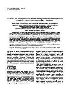
I. INTRODUCTION In the future e + e - linear colliders, multi-bunch beam operation is essential to get high luminosity. For the same reason, the spot size at the interaction point must be focused into quite small dimension, typically a few nanometer in vertical and a few hundred nanometer in horizontal. To achieve this small spot with multi-bunch beam, it is very important to accelerate low-emittance beam in the main-linac without deteriorating its emittance. Therefore, the wake-field problem in the linear accelerating structure is one of the most important R&D issue to realize the linear collider. To solve this problem, the choke mode cavity was devised by the author[1]. The concept of this structure is explained in Fig. 1. This structure is made of many copper disks. There are gaps between disks, the beam induced wake-fields ( or HOM : Higher-Order Modes ) can easily get out from the cavity through the gap, and all of HOM oscillations disappear before the successive bunched beam coming. In order to trap only the accelerating mode inside the cavity, the choke is attached in the gap. Since the choke has sharp notch-filter response, only the selected mode, the accelerating mode in this case, is trapped. On the other hand, all of the HOM power can get out smoothly without reflecting at the choke. Therefore, this structure shows quite effective damping on all HOMs for wide frequency range. If we apply this structure to the main linac for the linear collider, emittance degradation problem due to the long-range wake field can be perfectly eliminated.
* Visiting from KEK
In order to demonstrate feasibility of this structure, a hot model of 0.5 m long constant-gradient structure at Sband was fabricated[2,3] in 1993. The completed structure was installed in ATF injector linac at KEK. The high power processing was smoothly performed, finally an average accelerating gradient of 50 MV/m was obtained with 120 MW input power[4]. There was no difficulty on processing due to high voltage break down or multipacting discharges. Also, the beam acceleration test was performed, and the energy gain of 26.2 MeV was observed at 104 MW input power, which was good agreement with the design vale. With this success, the high power capability of this structure was fully proved. The next step of the R/D program has been started in 1995, a C-band model of this structure is now under developing, in which HOM absorbers will be loaded in each disks and also in-line dummy load will be integrated at the last few cells. In this paper, status of this R/D is reported. Wake Fields
Choke Filter
λ/4 λ/4
Trapped Accelerating Mode BEAM
Copper Disks Support & Cooling Water Channel
Fig. 1: Conceptual drawing of HOM-free accelerating structure using choke mode cavity.
linear
II. C-BAND STRUCTURE DESIGN We have proposed C-band rf system as one of the best solution to realize the large scale main linac for the e+ elinear colliders at 500 GeV to 1 TeV c.m. energy scale with minimum R/Ds and lower construction cost[5,6]. The designed parameter of the C-band structure is listed in Table 1, and its cross-sectional view is shown in
649
Fig. 2 The phase shift per cell is 3π/4, whose unit cell length is slightly longer than the 2π/3 mode, which make easy to get more room to fit the choke structure in each cell. The average shunt impedance in this structure is 55 MΩ/m, which is about 25% lower than that of conventional disk-loaded structure with same 2a, 2b dimensions. It does not mean we have to increase the input rf power by 25%. In a practical operation, the net accelerating gradient is always lowered due to the beam loading effect. This effect is smaller in lower shunt impedance structure, then the loss of the shunt impedance is somewhat compensated. In the C-band system, the pulse beam current is 0.57 A, and the beam loading effect is about 8 MV/m on the nominal accelerating gradient of 40 MV/m. To keep the same accelerating gradient in our structure of 25% lower shunt impedance, the input power has to be increased about 15%. Therefore, the power loss in the choke does not deteriorate the system efficiency so much. If we think about the big benefits of multibunch capability in this structure, this much of the power is not expensive. Table-1 Electrical Parameters Operating Frequency f 5712 MHz Phase Shift per Cell βD 3π/4 TW Structure Type const. grad. Wake field Control Damping Damping Qe < 10 Length L 1.81 m Number of Cells N 92 cells Cell Length D 19.68 mm Filling Time TF 281 nsec Attenuation Parameter τ 0.53 Iris Aperture a/λ 0.17 ~0.13 Group Velocity (%c) Vg/c 3.5 ~1.2 Quality Factor Q 9.5 x10³ r/Q 5.7 kΩ/m Shunt Impedance 55.0 MΩ/m Accelerating Gradient at 80 MW input Accelerating Gradient(1) Ea 40 MV/m RMS Straightens Tolerance(2) 35 µm/92 1) Unloaded gradient for 500 GeV c.m. case. 2) Tightest tolerance on structure straightens over N cells.
III. MICROWAVE ABSORBERS In the S-band high power model, we did not install the microwave absorber, because the main object in the test was demonstration of the high power capability of this new type of rf cavity. In the C-band structure design, we started R/D study on the microwave absorbers, including survey of material, its quality control, optimization of structure to meet rf matching, and brazing process. Engineering ceramic of SiC has already been used as microwave absorber. H. Matsumoto developed the first model of waveguide dummy-load for S-band microwave in
650
1981, and nearly 200 units of this dummy load were successfully used in KEK PF injector linac[7]. Recently, he developed a high-peak power model which can handle 50 MW, 1 µsec at S-band, in which disk shape SiCs(φ20 mm) were directly attached on copper waveguide by brazing. T. Koseki et. al.[8] have recently applied a SiC duct to HOM-damper on beam pipe close to an rf accelerating cavity. They reported the SiC duct made by Toshiba CERASIC-B ( resistivity of 20 Ωcm ) strongly reduced the Q-values of HOMs in the cavity. Because of these experiences, and also its good vacuum property we will employ SiC in our structure. We use disk shape SiC ( CERASIC-B ) of φ15-20 mm, directly attach them on each cell by brazing as shown in Fig. 2. The skin depth in SiC becomes 3 mm at C-band frequency, and the effective surface resistance becomes 6 Ω, which is same order as the characteristic impedance 5 Ω of TEM wave in the radial line at radius of 6 cm with 5 mm gap. Therefore the wakefields will be effectively absorbed in SiCs due to ohomic loss of the wall current.
IV VACUUM CHAMBER DESIGN In order to simplify the vacuum chamber and reduce number of the components, we will implement the in-line dummy load in the last few cells by coating the cavity with high resistivity metal. This technique has been used long time in medical accelerators[10]. The vacuum conductance from beam line to the tank is quite large, the structure can be pumped down to very low pressure level quickly. This is quite important feature, because recent studies[9] are indicating the existence of new type instability due to wakefield like effect by trapped ions in the residual gas, which can cause emittance dilution in the main linac or in the bunch compressor.
V. CELL COOLING Since this structure has to be used at high accelerating gradient and high repetition frequency in the liner collider, the cell cooling is one of the most important issue in practical usage. The expected maximum heat-dissipation per unit length is 3.2 kW/m. We assumed cooling water flow of 126 litter/min., and its temperature 21 deg.C, which flows along six cooling water channels of 12 mm inner diameter. We estimated heat dissipation density using SUPERFISH code, then put in these data into I-DEAS code to simulate the heat flow inside the copper-disk and heat transfer into the cooling water. According to this simulation, the maximum temperature at the top of the iris reaches 35.4 deg.C. This is quite high as compared to the traditional design of disk-loaded structure. We will implement a feedback loop which measures the rf phase at the end of the structure, and control the cooling water temperature and also the klystron input phase.
VI. ALIGNMENT TOLERANCE ON ACCELERATING STRUCTURE
(
C-band structure
Tolerance ( micron )
The alignment tolerance of accelerating structures can be estimated from an analytical expression of emittance growth. Expected emittance growth due to random misalignment of accelerating structures is approximately[11] 2 2 2 2 α α e q x rms Wrms β 0 La E f − E0 (1) < ∆ε >= α 2αE f E0 g where q is total charge, xrms the r.m.s. of misalignment, β0 initial averaged beta function, L a length of each structure, Ef final energy, E0 initial energy, g accelerating gradient and beta-function is assumed to be proportional to Eα., where α = 0.5. W rms is the r.m.s. of the wakefield effect and 2 2 W' σ 2 Wrms ≈ 0.91 s z (2) π for a single Gaussian bunch, where σ z is bunch length. W' s is slope of the transverse wake function which is assumed to be a linear function of distance and estimated as 19 3 W ' s ≈ 1.35 × 10 V / C / m (3) for structures with the aperture radius of 7.77 mm or a / λ of 0.148. Because of the strong damping (Q