Nov 22, 2015 - PETER and block high base-MAC link for BRAIN. ... PETER to STEWIE .... figure 2.1.1 that show three users Glenn, Herbert, and Chris are.
NETWORKS AND PROTOCOLS
SWITCHING
HOMEWORK 1 Due: 22.11.2015
Name: ID:
SALAUDDIN 5000642
1
Homework 1 Switching 1. Spanning Tree Protocol 2. Backward Learning
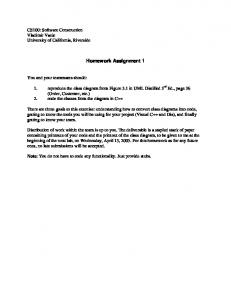
1. Spanning Tree Protocol:
Figure 01: Spanning Tree Protocol It is possible to design Figure 0.1 architecture using Cisco Packet Tracer software where switch priority can be modified using switch’s ISO command line Interface [1]. All switches hold same priority in Figure 0.1, links cost are equal by default [2]. Because, it is not possible to change base MAC address of switches in cisco packet tracer, switches are arranged exactly following the order of MAC address and position. For every switch, given base MAC address along with cisco packet tracer provided MAC address are separated by symbols “…..” what is represented in Figure 0.1. For example, switch STEWIE the Root-bridge actually contains second MAC address whereas first MAC address is given MAC address 00:02:95:9d:68:16...0001.9723.D706. Also switch’s ports MAC address can be declared using static MAC [3].
Homework 1 Switching 1. Spanning Tree Protocol 2. Backward Learning
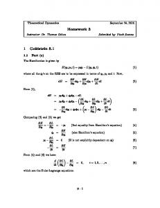
1.1 Generated STP protocol.
Figure 1.1: Spanning Tree generated by STP Protocol For computation and drawing the spanning tree generated by the STP protocol, first attempt to locate Root-bridge is obvious. Root-bridge is selected by finding the lowest priority number holding switch. Because all switches have same priority, the second method of locating root-bridge is to compare base-MAC addresses. The lowest base- MAC address holding switch is the Root-bridge defined by IEEE 802.1d. This implies that, in a network (without prior setting) the oldest switch, which likely to have lowest base-MAC from manufacturer is the root-switch. In this model STEWIE has the lowest base-MAC and declared as root-bridge. Now every switch has to find easiest path that is lowest cost to reach root-bridge. Figure 0.1 shows BRIAN can reach STEWIE through LOIS or PETER with same cost. Therefore, Spanning Tree Protocol compares base-MAC address of LOIS and PETER and block high base-MAC link for BRAIN.
Homework 1 Switching 1. Spanning Tree Protocol 2. Backward Learning
BRAIN to reach STEWIE Name LOIS to STEWIE PETER to STEWIE
(Assuming each link cost 1) Cost: 2 Cost: 2
BASE-MAC ADRESS 00:04:E7:28.81:00 00:1D:B3:09:85:15
Final Status Low MAC; Port Forward or Active High MAC; Port Blocked by STP
After computation, it has recognized that block links are c, e, f, and i. By deleting those block links; it is possible to draw Figure 1.1, what shows only active links of spanning tree protocol.
1.2. The root bridge and the root ports on all the non-root bridges.
Figure 1.2: Root-bridge and the root ports on all the non-root bridges Switch port that is connected to root-bridge or shortest path to the root-bridge is defined as root-port. If there is multiple link connected to the root-bridge from a non-root switch than port cost is define by link bandwidth and lowest port cost is announced as root-port (R.P). It is possible to appreciate Figure 1.2 that shows all root-ports for this architecture [4: Figure: A.2-A.5].
Homework 1 Switching 1. Spanning Tree Protocol 2. Backward Learning
1.3. The designated ports for each LAN segment.
Figure 1.3: Designated ports in root-bridge and all other non-root bridges All ports of a root-bridge are designated ports. After selection of root-port, the ports required to reach root-bridge are designated port. In spanning tree protocol the opposite port of block ports are designated ports. Obviously the links are block while any one port is blocked. It is possible to appreciate Figure 1.3 that show all designated ports (D.P) [4: Figure: A.1-A.5].
Homework 1 Switching 1. Spanning Tree Protocol 2. Backward Learning
1.4. The ports that are blocked.
Figure 1.4: All blocked ports by spanning tree protocol The Switch Ports will go into a blocking state at the time of election process, when a switch receives a BPDU on a port that indicates a better path to the Root Switch (Root Bridge), and if a port is not a Root Port or a Designated Port [10]. Figure 1.4 shows all block ports (B.P) in this network [4: Figure: A.3-A.5] [5].
Homework 1 Switching 1. Spanning Tree Protocol 2. Backward Learning
1.5. Fill in the port state for each port in the table below, once the SPT algorithm has converged. Switch
STEWIE
PETER
LOIS
MEG
BRIAN
Port/Base MAC
MAC
Port State
S1
00:0A:95:9d:68:16
Designated Port
S2
00:02:95:9d:68:16
Designated Port
S3
00:01:94:9d:68:16
Designated Port
Base MAC
00:02:95:9d:68:16
Root Bridge
P1
00:1C:B3:09:85:15
Root Port
P2
00:1B:B3:09:85:15
Designated port
P3
00:1A:B3:09:85:15
Block port
Base MAC
00:1D:B3:09:85:15
Non-Root Bridge
L1
00:01:E7:28.81:00
Root Port
L2
00:02:E7:28.81:00
Designated Port
L3
00:03:E7:28.81:00
Designated Port
Base MAC
00:04:E7:28.81:00
Non-Root Bridge
M1
00:07:B7:28:81:01
Root Port
M2
00:06:B7:28:81:02
Designated Port
M3
00:05:B7:28:81:03
Block Port
M4
00:05:B7:28:80:03
Designated Port
Base MAC
00:07:B7:28:81:04
Non-Root Bridge
B1
00:05:A7:20:61:03
Root Port
B2
00:05:A7:20:61:04
Block Port
B3
00:05:A7:20:61:05
Block Port
Base MAC
00:05:A7:20:60:01
Non-Root Bridge
Table 1.5: state of each port after STP algorithm has converged.
Homework 1 Switching 1. Spanning Tree Protocol 2. Backward Learning
All Ports status of STP Network
Figure 1.5: Complete ports status calculated by spanning tree protocol
Homework 1 Switching 1. Spanning Tree Protocol 2. Backward Learning
1.6. Link d fails & Re-computation the spanning tree
Figure 1.6: Re-computation of spanning tree protocol while link: d fails It is possible to appreciate Figure 1.6 that shows if link: d fails than STP again calculates the shortest path from all non-root bridges to root-bridge and in 15 second those blocked port up again. For instance, previously port P3 that is link: c was blocked but, after link: d fails switch PETER has no connection with root-bridge through port P1. Therefore, to establish connection between root-bridge and PETER, link: c goes up now by STP.
Homework 1 Switching 1. Spanning Tree Protocol 2. Backward Learning
All Ports status of STP Network while Link: d Fails
Figure 1.6: All ports status while link: d fails Figure 1.6 shows all ports status after recalculating STP while link: d fails. In this network root-bridge remain unchanged marked by red circle that is STEWIE. All other bridge’s root ports are marked with yellow squire boxes on this network.
Homework 1 Switching 1. Spanning Tree Protocol 2. Backward Learning
2. Backward Learning:
Figure 2.1.1: Three users, Glenn, Herbert, and Chris are added to the network. It is possible to appreciate figure 2.1.1 that show three users Glenn, Herbert, and Chris are added to the network and GLENN wants to send Ethernet frame to CHRIS. Initially GLENN knows only the Internet Protocol (IP) Address of CHRIS and switches have no entry of GLENN and CHRIS’s MAC addresses [8]. GLENN needs MAC address of CHRIS to send Ethernet frame. Therefore, GLENN broadcast an ARP massage to discover CHRIS’s MAC address [9]. It is possible broadcast an ARP message on cisco packet trace and switches update its MACK address-table from header information as soon as receive an ARP packet [9]. While CHRIS reply with his MAC address than switches receive replied ARP packet and from header information updates its MAC address table before forwarding [9]. For switches this process of learning MAC address is called “Backward Learning” [9]. 2.1 User Glenn wants to send an Ethernet frame to user Chris. Therefore, GLENN Broadcast an ARP message to discover CHRIS’s MAC Address PORT S4
STEWIE Contents GLENN’s MAC
LINK
PORT
j
L1
LOIS Contents GLENN’s MAC
LINK
PORT
a
B1
BRIAN Contents GLENN’s MAC
LINK
PORT
b
M1
MEG Contents GLENN’s MAC
LINK
PORT
g
P1
Table 2.1.1: contents of the forwarding database, as entries are learned by Bridges.
PETER Contents GLENN’s MAC
LINK d
Homework 1 Switching 1. Spanning Tree Protocol 2. Backward Learning
Backward Learning: PORT B4
BRIAN Contents CHRIS’s MAC
LINK
PORT
k
L3
LOIS Contents CHRIS’s MAC
LINK
PORT
b
S3
STEWIE Contents CHRIS’s MAC
LINK a
Table 2.1.2: Bridges Backward Learning.
2.2 User Herbert wants to send an Ethernet frame to user Glenn. Therefore, Herbert Broadcast an ARP message to discover Glenn’s MAC Address. PORT M5
MEG Contents HERBERT’s MAC
LINK l
PORT S1
STEWIE Contents HERBERT’s MAC
LINK g
PORT L1
LOIS Contents
LINK
HERBERT’s MAC
a
PORT P1
PETER Contents HERBERT’s MAC
LINK d
PORT B1
Table 2.2.1: contents of the forwarding database, as entries are learned by Bridges.
Backward Learning: PORT S4
STEWIE Contents GLENN’s MAC
LINK
PORT
j
M1
MEG Contents GLENN’s MAC
LINK g
Table 2.2.2: Bridges Backward Learning.
BRIAN Contents HERBERT’s MAC
LINK b
Homework 1 Switching 1. Spanning Tree Protocol 2. Backward Learning
Appendix
1. Switch priority setting command: MEG(config)#spanning-tree vlan 1 priority ? bridge priority in increments of 4096 Priority of a switch can be checked using “show spanning-tree” command in privilege mode. Figures: A.1-A.5 shows that all switches configured with same priority of 4097. 2. It is possible to appreciate Figures: A.1-A.5 that every link cost is 19 by default. 3.
Figure A.0: command for configuration of static port MAC address
Homework 1 Switching 1. Spanning Tree Protocol 2. Backward Learning
It is possible to appreciate Figure A.0 that shows the command for configuration of static port MAC address according to task desire. In this Figure green squire shows current ports MAC status what match perfectly with task in case of switch STWEWIE.
4. Every switch port status and switch priority can be checked using following commands:
Figure A.1: All port status of root-bridge STEWIE
Homework 1 Switching 1. Spanning Tree Protocol 2. Backward Learning
Figure A.2: All port status of non-root-bridge LOIS
Homework 1 Switching 1. Spanning Tree Protocol 2. Backward Learning
Figure A.3: All port status of non-root-bridge BRIAN
Homework 1 Switching 1. Spanning Tree Protocol 2. Backward Learning
Figure A.4: All port status of non-root-bridge MEG
Homework 1 Switching 1. Spanning Tree Protocol 2. Backward Learning
Figure A.5: All port status of non-root-bridge PETER
5. Problem faced to select block port while comparing between switch PETER and MEG that is link: c and ports between P3 and M1, also between switches MEG and BRAIN. According to STP protocol decision is made following three step rules are Priority, Cost, Physical Address (MAC) and they are followed sequentially. Therefore, while calculating block port cost has to be considered first. For example, from switch P3 to root cost is 2 (considering all link cost are same and is equal to 1) while switch port M1 to root cost 1 therefore, P3 port is blocked.
Homework 1 Switching 1. Spanning Tree Protocol 2. Backward Learning
6. Command help: http://www.cisco.com/c/en/us/td/docs/switches/datacenter/nexus5000/sw/configuration/guide/cli /CLIConfigurationGuide/MACAddress.html 7. https://www.cbtnuggets.com/ 8.
Figure A.2.1.1: MAC Address Table of STEWIE
Homework 1 Switching 1. Spanning Tree Protocol 2. Backward Learning
Figure A.2.1.2: MAC Address Table of LOIS
Homework 1 Switching 1. Spanning Tree Protocol 2. Backward Learning
Figure A.2.1.3: MAC Address Table of BRIAN
Homework 1 Switching 1. Spanning Tree Protocol 2. Backward Learning
Figure A.2.1.4: MAC Address Table of MEG
Homework 1 Switching 1. Spanning Tree Protocol 2. Backward Learning
Figure A.2.1.5: MAC Address Table of PETER
Homework 1 Switching 1. Spanning Tree Protocol 2. Backward Learning
9. Step 1:
Figure A.2.1.6: ARP Request Set by GLENN First open Edit filter to mark only ARP and command Prompt of GLENN typing ping 192.168.10.2 (IP address of CHRIS) than ARP packet is set to broadcast on this network. In figure A.2.1 red block shows Target (unknown) MAC of CHRIS need to be discovered and green block indicates source (GLENN) MAC address. So far, GLENN only knows Target IP what is show at the end part of ARP packet.
Homework 1 Switching 1. Spanning Tree Protocol 2. Backward Learning
Step2:
Figure A.2.1.7: STEWIE Receives ARP packet through Link: J As soon as STEWIE receive ARP packet, it update its MAC address table. STEWIE is connected with GLENN through interface first Ethernet 0/4. Figure A.2.1.7 shows STEWIE’s updated MAC address-table contains GLENN’s MAC address on port fa0/4.
Homework 1 Switching 1. Spanning Tree Protocol 2. Backward Learning
Step 3:
Figure A.2.1.8: LOIS Receives ARP packet through Link: a from STEWIE
Homework 1 Switching 1. Spanning Tree Protocol 2. Backward Learning
Figure A.2.1.9: MEG Receives ARP packet through Link: i from STEWIE
Homework 1 Switching 1. Spanning Tree Protocol 2. Backward Learning
Figure A.2.1.10: PETER Receives ARP packet through Link: d from STEWIE
Homework 1 Switching 1. Spanning Tree Protocol 2. Backward Learning
Step 4:
Figure A.2.1.11: BRAIN Receives ARP packet through Link: b from LOIS
Homework 1 Switching 1. Spanning Tree Protocol 2. Backward Learning
Step 5:
Figure A.2.1.12: CHRIS Receives ARP packet And Reply Figure A.2.1.12 shows CHRIS set ARP massage for GLENN by providing own MAC as source MAC and GLENN’s MAC as Destination MAC. In this ARP packet source IP is CHRI’s IP address that is 192.168.10.2 and target IP that is 192.168.10.1 is GLENN’s IP address.
Homework 1 Switching 1. Spanning Tree Protocol 2. Backward Learning
Step 6:
Figure A.2.1.13: BRAIN Receives ARP packet From CHRIS through Link: k Figure A.2.1.13 shows that BRAIN updates it MAC address-table by adding CHRIS MAC address in port interface Fa0/4. This MAC address updating mechanism is known as Backward Learning.
Homework 1 Switching 1. Spanning Tree Protocol 2. Backward Learning
Step 7:
Figure A.2.1.14: LOIS Receives ARP packet From BRAIN through Link: B Figure A.2.1.14 shows that LOIS updates it MAC address-table by adding CHRIS MAC address in port interface Fa0/2. Again, this is Backward Learning for LOIS.
Homework 1 Switching 1. Spanning Tree Protocol 2. Backward Learning
Step 8:
Figure A.2.1.15: STEWIE Receives ARP packet From LOIS through Link: a Figure A.2.1.15 shows that STEWIE updates it MAC address-table by adding CHRIS MAC address in port interface Fa0/1.
Homework 1 Switching 1. Spanning Tree Protocol 2. Backward Learning
Step 9:
Figure A.2.1.16: GLENN Receives ARP packet From STEWIE through Link: J
Homework 1 Switching 1. Spanning Tree Protocol 2. Backward Learning
Step 10:
Figure A.2.1.17: GLANN does not have CHRICS MAC address A method to check ARP working is that before sending ARP packet if we type “arp” –a in command prompt in GLENN PC that figure A.2.1.17 shows no information.
Homework 1 Switching 1. Spanning Tree Protocol 2. Backward Learning
Figure A.2.1.18: GLANN have CHRICS MAC address Figure A.2.1.18 shows that after sending and receiving ARP packet, now GLENN has MAC address of CHRIS.
10. http://www.omnisecu.com/cisco-certified-network-associate-ccna/spanning-tree-portstates.php