B. L i). During read operation with Q = V D D , the corresponding schematic ... We can get some more appropriate values of the threshold voltages for the ...
Homework 6 Solution E
C
E
E
5
C
5
E
9
D
:
e
M
p
O
a
S
r
t
V
m
L
e
S
n
I
t
D
,
e
P
s
u
i
r
g
d
n
u
(
e
F
a
U
l
n
i
l
2
v
0
e
r
0
s
9
i
t
)
y
Assigned: 18-Nov-2009 I
m
p
d
u
b
r
y
P
o
i
n
a
u
a
b
l
n
s
m
o
t
g
e
r
r
e
i
t
b
l
i
m
:
P
m
f
i
s
1
s
u
l
s
e
i
c
a
o
h
s
e
n
n
t
o
e
e
u
f
d
y
a
r
n
o
-
u
r
i
Due: 24-Nov-2009
i
n
r
s
a
s
e
s
l
o
l
l
u
o
t
i
f
o
y
n
.
o
u
Y
r
o
c
u
o
d
m
e
a
s
y
a
b
e
l
a
o
n
s
g
k
w
e
i
d
t
t
h
t
o
p
h
r
e
o
v
w
i
d
a
e
v
t
e
h
f
e
o
r
s
o
m
s
f
t
(
c
o
w
h
p
y
e
n
o
n
f
y
e
o
c
u
e
r
s
s
c
a
o
r
d
y
e
)
s
.
:
Consider a standard 6-T SRAM cell. Use the following parameters. L = 300 nm, VDD = 2.5 V. and widths are 450 nm and 1800 nm, For all the NMOS transistors, allowed respectively. Always size the pull-up PMOS transistors as three-times the widths of the pulldown NMOS transistors. You should consider widths in intervals. m
i
n
i
m
u
m
m
a
x
i
5
0
m
u
m
n
m
Write your assumptions with clear and concise explanation for all the parts below. P
a
r
t
a
)
Determine by hand calculation i) ii)
C
e
P
u
l
l
l
r
l
-
a
u
t
p
i
o
r
a
(ratio of the widths of pull-down NMOS and access transistor) for read (ratio of the widths of pull-up PMOS and access transistor) for write t
i
o
Write the regions of operation of all the transistors for both i) and ii). Any extra parameter that you might need, you should are using. o
l
u
t
i
o
n
e
x
t
r
a
c
t
from the SPICE library that you
:
S
From the SPICE libraries,
t
s
m
c
2
5
N
and
t
s
m
c
2
5
P
, we get
Vtn0 = 0.431 V, Vtp0 = -0.616 V. Also, µn0 = 455.4 cm2/V/S, µp0 = 158.7 cm2/V/S.
Page 1 of 16
Homework 6 Solution
ECE 559 (Fall 2009), Purdue University
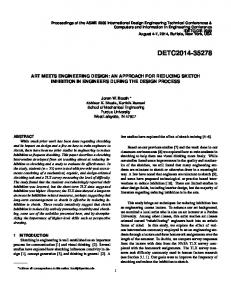
A schematic diagram of a standard 6-T SRAM cell is given below. W
L
V
D
M
D
2
M
4
Q M
5
M
6
Q
M
1
M
3
L
L
B
i)
B
During read operation with
Q
=
V
D
, the corresponding schematic diagram is shown
D
below. When the voltage at node Q reaches the threshold voltage of the NMOS, M3 (see the complete 6-T cell), the voltage at node Q starts to fall and the regenerative action of the cross-coupled inverter will force the flipping of the bit in the cell. V
W
L
=
D
D
V
D
D
M
V
4
V
=
D
D
t
Q
=
M
5
M
6
0
Q
V
D
M
D
1
V
L
V
=
L
D
D
=
D
B
B
Page 2 of 16
D
Homework 6 Solution
ECE 559 (Fall 2009), Purdue University
We can get some more appropriate values of the threshold voltages for the transistors by doing operating point analysis (.OP command in SPICE). To do an operating point analysis, we need to set the terminals voltages of an MOS and use .OP command that will print different extracted parameters (e.g., vth) for the MOS. First, we can do an operating point analysis for the NMOS, M3 to get the voltage Vt. Then we can use the value of Vt to perform operating point analyses for the MOSs M1 and M5. For the access transistors we should notice that there is which can increase their threshold voltages. o
b
V
a
t
V
e
o
l
t
a
g
e
r
a
i
o
f
e
f
c
t
l
t
a
g
e
o
u
r
c
V
e
o
l
t
a
g
e
u
b
s
t
r
a
t
e
o
l
t
a
g
e
h
S
V
r
e
s
h
o
l
d
T
V
V
V
V
G
(
)
(
)
(
)
(
)
o
l
t
a
g
e
(
)
O
M3 M1 M5 e
e
S
V
M
-
y
V
n
D
S
d
g
i
o
n
0.491 2.5 2.5 s
o
f
o
p
e
r
a
t
i
o
n
f
o
2.5 0.491 2.5 r
t
h
e
t
r
a
n
s
i
s
t
o
r
s
0 0 0.491
0 0 0
0.491 0.511 0.581
:
R
1
M
:
:
Linear,
M
2
:
Cut-off,
M
3
:
Cut-off,
M
4
:
Linear,
M
5
:
Saturation,
M
Cut-off.
6
We can write the regions of operation of the transistors similarly when operation.
Q
=
during read
0
To prevent read failure, the transistor M1 should be strong enough so that the voltage at node Q does not rise more than Vt = 0.491 V. Accordingly,
IM1 ≥ IM 5 0.4912 W ( 2.5 − 0.491 − 0.581) W ⇒ ( 2.5 − 0.511) *0.491 − ≥ 2 L 5 2 L 1 W 1.0196 ⇒ 1≥ W5 0.8561 ⇒ CR =
W1 ≥ 1.191. W5
Page 3 of 16
2
Homework 6 Solution
ii)
ECE 559 (Fall 2009), Purdue University
During write operation, say we are going to write while initially , the corresponding schematic diagram is shown below. When the voltage at node Q reaches a voltage so that the PMOS, M2 (see the complete 6-T cell) gets ON, the voltage at node Q
=
Q
0
=
V
D
D
Q starts to rise and the regenerative action of the cross-coupled inverter will force the write
Q
=
.
0
V
W
L
=
D
D
V
D
D
M
4
V
V
=
D
D t
Q
=
M
5
M
6
0
Q
V
D
M
D
1
V
L
=
L
D
=
0
D
B
B
First, we can do an operating point analysis for the PMOS, M2 to get the voltage Vt. Then we can use the value of Vt to perform operating point analyses for the MOSs M4 and M6. V
a
t
V
e
o
l
t
a
g
e
r
a
i
V
n
o
l
t
a
g
e
o
V S
c
V
e
o
l
t
a
g
e
u
b
s
t
r
a
t
e
o
l
t
a
g
e
h
S
V
r
e
s
h
o
l
d
T
V
V
V
V
)
(
)
(
)
(
)
o
l
t
a
g
e
(
)
O
M2 M4 M6 e
r
G
(
M
u
S
D
g
i
o
n
(2.5 - 0.517) 0 2.5 s
o
f
o
p
e
r
a
t
i
o
n
f
o
0 (2.5 - 0.517) 0 r
t
h
e
t
r
a
n
s
i
s
t
o
r
s
2.5 2.5 (2.5 - 0.517)
2.5 2.5 0
-0.517 -0.526 0.496
:
R
1
:
:
Linear,
M
M
2
:
Cut-off,
M
3
:
Cut-off,
M
4
:
Linear,
M
5
:
Saturation,
M
6
Linear.
We can write the regions of operation of the transistors similarly for writing initially . Q
=
0
Page 4 of 16
Q
=
V
D
D
while
Homework 6 Solution
ECE 559 (Fall 2009), Purdue University
To prevent write failure, the transistor M6 should be strong enough so that the voltage at node Q does go below Vt = (2.5 - 0.517) V = 1.983 V. Accordingly, 2 −1.983) ( W −3* ( 2.5 − 1.983 − 0.496 )( −1.983) − 2 L 6 2 1.983 − 2.5) ( W ≥ ( −2.5 + 0.526 )(1.983 − 2.5) − 2 L 4
⇒
W4 3*0.8869 ≤ W6 2.0078
⇒ PR =
W4 ≤ 1.325. W6
Please note that µn0≈ 3*µp0 has been used in the above calculation. For the NMOS M6, the terminal attached to BL has been assumed as . d
o
t
e
r
a
i
n
:
Both the cell ratio and pull-up ratio are restricted and endorsed by the minimum width allowable by a technology library and the requirement of having high-density of memory array (i.e., having lower widths of the transistors). Also, notice that we have assumed same L (= 300 nm) for all the transistors. N
Page 5 of 16
Homework 6 Solution P
a
r
t
b
ECE 559 (Fall 2009), Purdue University
)
Size the transistors in the SRAM cell to have the . By SPICE simulation, determine the (SNM) of the SRAM cell. (SNM is defined as the minimum noise voltage present at each of the cell storage nodes necessary to flip the state of the cell.) Explain the procedure you have followed. m
s
o
l
u
t
i
o
n
t
a
t
i
c
n
o
i
s
e
m
a
r
g
i
a
x
i
m
u
m
r
e
a
d
s
t
a
b
i
l
i
t
y
n
:
S
For maximum read stability, the should be as high as possible. With the allowable values provided, we should choose the following widths of the transistors for maximum read stability. c
1
M
:
/
M
M
l
l
r
a
t
i
o
:
/
1800 nm,
3
e
M
2
:
/
5400 nm,
4
M
M
5
450 nm.
6
(SNM) for an SRAM cell is shown the figure below. The SNM The concept of is defined as the minimum noise voltage present at of the cell storage nodes necessary to flip the state of the cell. A basic understanding of the SNM is obtained by drawing and mirroring the inverter characteristics and then finding the square between them. s
t
a
t
i
c
n
o
i
s
e
m
a
r
g
i
n
e
m
a
x
a
i
Page 6 of 16
m
c
h
u
m
Homework 6 Solution i
m
u
l
a
t
i
o
n
e
t
h
o
d
ECE 559 (Fall 2009), Purdue University b
a
s
e
d
o
n
r
a
p
h
i
c
a
l
e
S
c
h
n
i
q
u
e
:
T
M G
We can determine the SNM graphically from the inverter characteristics. However, we have to perform one SPICE simulation having voltage controlled voltage sources (VCVS) that will be clear onwards. You can use the following reference for details. e
f
e
r
e
n
c
e
R
Seevinck, E., List, F. J., and Lohstroh, J., “Statis-Noise Margin Analysis of MOS SRAM Cells,”, IEEE Journal of Solid-State Circuits, Vol. SC-22, No. 5, October, 1987. A 45o rotated picture corresponding to the butterfly curve is shown below. The voltage from -Vdd/√2 to Vdd/√2.
o
N
t
e
spans
U
:
Please note that both the previous figures are obtained by choosing word line, WL = 0.
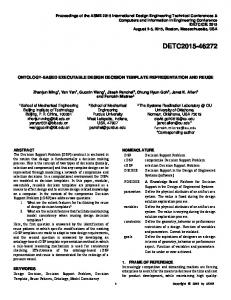
When read process is initiated, i.e., WL is made logic high, the inverter characteristics changes and hence the SRAM cell gets vulnerable to noise. We are asked to determine the SNM while it’s reading. The corresponding SPICE code to determine the SNM and the modified butterfly curves during read access are given next. From the SPICE code we get the following values. e
W
c
a
n
s
e
e
t
h
a
t
t
h
e
g
S
N
M
Page 7 of 16
e
t
s
d
e
c
r
e
a
s
e
d
d
u
r
i
n
g
r
e
a
d
a
c
c
e
s
s
.
Homework 6 Solution
ECE 559 (Fall 2009), Purdue University V
o
r
d
W
i
n
e
L
(
)
W
t
a
t
i
c
o
S
L
i
s
e
a
r
g
i
n
(
)
S
N
M
Logic 0 Logic 1 (read)
(
)
N
M
0.8146 0.6521
Please note that, 1pF of bitline capacitance has been used to simulate the effect of having a memory array. Butterfly curve for the SRAM cell (read access) 2.5
VQB (V)
2
1.5
1
0.5
0 0
0.5
1
1.5
2
2.5
VQ (V)
Rotated (45o ) butterfly curve (read access) 2.4
VQ, VQB (V)
2.2
2
1.8
1.6
1.4 -2
-1.5
-1
-0.5
0
0.5
U (V)
Page 8 of 16
1
1.5
2
Homework 6 Solution
S
P
I
C
E
C
o
d
e
(
G
r
a
p
ECE 559 (Fall 2009), Purdue University
h
i
c
a
l
T
e
c
h
n
i
q
u
e
)
* HW 6, Problem 1, Determination of SNM graphically * ECE 559, Fall 2009, Purdue University .TEMP 25.0000 .lib "$CDK_DIR/models/hspice/public/publicModel/tsmc25N" NMOS .lib "$CDK_DIR/models/hspice/public/publicModel/tsmc25P" PMOS .GLOBAL VDD! .PARAM VDD = 2.5 .PARAM L = 300n .PARAM WN = 1800n .PARAM WP = '3*WN' .PARAM WNA = 450n .PARAM U = 0 .PARAM UL = '-VDD/sqrt(2)' .PARAM UH = ' VDD/sqrt(2)' .PARAM BITCAP = 1e-12 .OPTION POST CBL BLB 0 BITCAP CBLB BL 0 BITCAP * one inverter MPL QD QB VDD! VDD! TSMC25P L='L' W='WP' +AD='WP*2.5*L' AS='WP*2.5*L' PD='2*WP+5*L' PS='2*WP+5*L' +M=1 MNL QD QB 0 0 TSMC25N L='L' W='WN' +AD='WN*2.5*L' AS='WN*2.5*L' PD='2*WN+5*L' PS='2*WN+5*L' +M=1
Page 9 of 16
Homework 6 Solution
ECE 559 (Fall 2009), Purdue University
* one inverter MPR QBD Q VDD! VDD! TSMC25P L='L' W='WP' +AD='WP*2.5*L' AS='WP*2.5*L' PD='2*WP+5*L' PS='2*WP+5*L' +M=1 MNR QBD Q 0 0 TSMC25N L='L' W='WN' +AD='WN*2.5*L' AS='WN*2.5*L' PD='2*WN+5*L' PS='2*WN+5*L' +M=1 * access transistors MNAL BLB WL QBD 0 TSMC25N L='L' W='WNA' +AD='WNA*2.5*L' AS='WNA*2.5*L' PD='2*WNA+5*L' PS='2*WNA+5*L' +M=1 MNAR BL WL QD 0 TSMC25N L='L' W='WNA' +AD='WNA*2.5*L' AS='WNA*2.5*L' PD='2*WNA+5*L' PS='2*WNA+5*L' +M=1 VVDD! VDD! 0
DC=VDD
* when reading, use VDD VWL WL 0 DC=VDD .IC V(BL) = VDD .IC V(BLB) = VDD * use voltage controlled voltage sources (VCVS) * changing the co-ordinates in 45 degree angle EQ Q 0 VOL=' 1/sqrt(2)*U + 1/sqrt(2)*V(V1)' EQB QB 0 VOL='-1/sqrt(2)*U + 1/sqrt(2)*V(V2)' * inverter characteristics EV1 V1 0 VOL=' U + sqrt(2)*V(QBD)' EV2 V2 0 VOL='-U + sqrt(2)*V(QD)' * take the absolute value for determination of SNM EVD VD 0 VOL='ABS(V(V1) - V(V2))'
Page 10 of 16
Homework 6 Solution
ECE 559 (Fall 2009), Purdue University
.DC U UL UH 0.01 .PRINT DC V(QD) V(QBD) V(V1) V(V2) .MEASURE DC MAXVD MAX V(VD) * measure SNM .MEASURE DC SNM param='1/sqrt(2)*MAXVD' .END
S
P
I
C
E
C
o
d
e
(
T
r
i
a
l
-
a
n
d
-
E
r
r
o
r
T
e
c
h
n
i
q
u
e
)
* HW 6, Problem 1, SNM by SPICE simulation * ECE 559, Fall 2009, Purdue University .TEMP 25.0000 .lib "$CDK_DIR/models/hspice/public/publicModel/tsmc25N" NMOS .lib "$CDK_DIR/models/hspice/public/publicModel/tsmc25P" PMOS .GLOBAL VDD! .PARAM VDD = 2.5 .PARAM L = 300n .PARAM WN = 1800n .PARAM WP = '3*WN' .PARAM WNA = 450n .PARAM VNOISE = 0.66 .PARAM BITCAP = 1e-12 .OPTION POST CBL BLB 0 BITCAP
Page 11 of 16
Homework 6 Solution
ECE 559 (Fall 2009), Purdue University
CBLB BL 0 BITCAP * one inverter MPL Q QBN VDD! VDD! TSMC25P L='L' W='WP' +AD='WP*2.5*L' AS='WP*2.5*L' PD='2*WP+5*L' PS='2*WP+5*L' +M=1 MNL Q QBN 0 0 TSMC25N L='L' W='WN' +AD='WN*2.5*L' AS='WN*2.5*L' PD='2*WN+5*L' PS='2*WN+5*L' +M=1 * one inverter MPR QB QN VDD! VDD! TSMC25P L='L' W='WP' +AD='WP*2.5*L' AS='WP*2.5*L' PD='2*WP+5*L' PS='2*WP+5*L' +M=1 MNR QB QN 0 0 TSMC25N L='L' W='WN' +AD='WN*2.5*L' AS='WN*2.5*L' PD='2*WN+5*L' PS='2*WN+5*L' +M=1 * access transistors MNAL BLB WL QB 0 TSMC25N L='L' W='WNA' +AD='WNA*2.5*L' AS='WNA*2.5*L' PD='2*WNA+5*L' PS='2*WNA+5*L' +M=1 MNAR BL WL Q 0 TSMC25N L='L' W='WNA' +AD='WNA*2.5*L' AS='WNA*2.5*L' PD='2*WNA+5*L' PS='2*WNA+5*L' +M=1 VVDD! VDD! 0 VWL
DC=VDD
WL 0 DC=VDD
VNOISEL QBN QB DC=VNOISE VNOISER Q QN DC=VNOISE .IC V(Q) = VDD .IC V(QB) = 0 .IC V(BL) = VDD .IC V(BLB) = VDD
Page 12 of 16
Homework 6 Solution
ECE 559 (Fall 2009), Purdue University
.TRAN 0.1n 1.5n UIC .PRINT TRAN V(QB) V(Q) V(BLB) V(BL) .END
o
t
e
:
N
1. We can vary the voltage and check in the output of the print command if the bit stored in the cell is flipping or not. We notice that when changes from 0.65 V to 0.66 V, the bit stored in the cell flips. Accordingly, the SNM would be which quite matches with the value that has been achieved by the graphical technique (0.6521 V). O
V
I
S
E
N
O
V
I
S
E
N
V
.
0
6
5
2. Notice the polarity of the noise voltage sources at the input of each inverter. It depends on the logic value of the bit stored in the cell. V
W
L
=
D
D
N
Q
B
Q
B
Q
-
+
V
=
D
D
Q
=
0
Q
-
N
Q
B
Q
+
Q
V
L
V
=
L
D
D
=
D
B
B
Page 13 of 16
D
Homework 6 Solution P
a
r
t
c
ECE 559 (Fall 2009), Purdue University
)
What happens to the write operation for the cell? If write operation fails, size the transistors in such a way that it’s at the verge of satisfying the write operation. By SPICE simulation, determine the (SNM) of the SRAM cell. Explain the procedure you have followed. s
t
a
t
i
c
n
o
i
s
e
m
a
r
i
g
n
Compare SNM for this part with that of part b). Explain if the result is according to your expectation or not. o
l
u
t
i
o
n
:
S
w
r
i
t
e
o
p
e
r
a
t
i
o
n
When we check for the
f
a
i
l
s
, it
.
As discussed in the part a), we understand that we can reduce the width of the pull-up PMOS transistors to facilitate write operation. This can be done by choosing lower widths of the pulldown NMOS transistors (as we are asked to choose always the widths of the pull-up PMOS transistors as three-times the widths the pull-down NMOS transistors). At the verge of satisfying the write operation, we find 1
:
/
M
M
:
/
750 nm,
3
M
M
2
:
/
2250 nm,
4
M
M
5
450 nm.
6
V
.
The corresponding SNM has been found to be
.
0
5
Similar procedure as in part b) is followed. Y
e
s
,
i
t
m
e
e
t
s
t
h
e
e
x
p
e
c
t
a
t
i
o
n
The SNM for the part c) is found to be less than that of part b). as we are of the cell by reducing the width of the pull-down NMOS transistors. r
S
P
I
C
E
C
e
o
u
d
d
c
i
n
g
t
h
e
r
e
a
d
s
t
a
b
i
l
i
t
y
e
* HW 6, Problem 1, Part c) Solution * ECE 559, Fall 2009, Purdue University .TEMP 25.0000 .lib "$CDK_DIR/models/hspice/public/publicModel/tsmc25N" NMOS .lib "$CDK_DIR/models/hspice/public/publicModel/tsmc25P" PMOS .GLOBAL VDD! .PARAM VDD = 2.5
Page 14 of 16
Homework 6 Solution
ECE 559 (Fall 2009), Purdue University
.PARAM L = 300n .PARAM WN = 750n .PARAM WP = '3*WN' .PARAM WNA = 450n .PARAM VNOISE = 0 .PARAM BITCAP = 1e-12 .OPTION POST CBL BLB 0 BITCAP CBLB BL 0 BITCAP * one inverter MPL Q QBN VDD! VDD! TSMC25P L='L' W='WP' +AD='WP*2.5*L' AS='WP*2.5*L' PD='2*WP+5*L' PS='2*WP+5*L' +M=1 MNL Q QBN 0 0 TSMC25N L='L' W='WN' +AD='WN*2.5*L' AS='WN*2.5*L' PD='2*WN+5*L' PS='2*WN+5*L' +M=1 * one inverter MPR QB QN VDD! VDD! TSMC25P L='L' W='WP' +AD='WP*2.5*L' AS='WP*2.5*L' PD='2*WP+5*L' PS='2*WP+5*L' +M=1 MNR QB QN 0 0 TSMC25N L='L' W='WN' +AD='WN*2.5*L' AS='WN*2.5*L' PD='2*WN+5*L' PS='2*WN+5*L' +M=1 * access transistors MNAL BLB WL QB 0 TSMC25N L='L' W='WNA' +AD='WNA*2.5*L' AS='WNA*2.5*L' PD='2*WNA+5*L' PS='2*WNA+5*L' +M=1 MNAR BL WL Q 0 TSMC25N L='L' W='WNA' +AD='WNA*2.5*L' AS='WNA*2.5*L' PD='2*WNA+5*L' PS='2*WNA+5*L'
Page 15 of 16
Homework 6 Solution
ECE 559 (Fall 2009), Purdue University
+M=1 VVDD! VDD! 0 VWL
DC=VDD
WL 0 DC=VDD
VNOISEL QBN QB DC=VNOISE VNOISER Q QN DC=VNOISE * logic 1 is stored in the cell initially .IC V(Q) = VDD .IC V(QB) = 0 * writing logic 0 in cell .IC V(BL) = 0 .IC V(BLB) = VDD .TRAN 0.1n 30n UIC .PRINT TRAN V(QB) V(Q) V(BLB) V(BL) .END
o
t
e
:
N
1. We can vary the parameter and check in the output of the print command if the bit stored in the cell is flipping or not. We notice that when changes from 800nm to 750nm, the bit stored in the cell flips. Accordingly, when , the cell is at the verge of satisfying the write operation. W
N
W
N
n
W
N
=
m
0
7
5
2. Note that we could have increased the widths of the access transistors to bring the cell at the verge of satisfying the write operation, however, it shouldn’t be chosen as in that case we would have higher widths of the transistors in the cell affecting the density of memory array.
Page 16 of 16