Horizontal Earthquake Loading and Linear/Nonlinear Seismic. Behaviour of Double Layer. Barrel Vaults. Arjang Sadeghi. Azarbaidjan University T.M., Tabriz, ...
Horizontal Earthquake Loading and Linear/Nonlinear Seismic Behaviour of Double Layer Barrel Vaults Arjang Sadeghi Azarbaidjan University T.M., Tabriz, Iran (Received 3 October 2003) ABSTRACT: Lattice space structures are one of the most common choices for covering large areas. These structures are also used as temporary shelters after strong and destructive earthquakes. Nevertheless, there are not enough available research results on the seismic behaviour of these structures. In the current work, the dynamic characteristics of the double layer barrel vaults are studied. Linear and nonlinear behaviour of the barrel vaults are investigated. It is shown that the barrel vaults are vulnerable to earthquakes and show brittle behaviour and therefore need to be designed carefully. For simplifying the assessment procedure of the earthquake equivalent loading on the barrel vaults some formulae are presented.
1. INTRODUCTION Space structures are widely used to cover large areas. Lattice space structures are among the mostly used families of the space structures. Also, among the common configurations of this family are the double layer barrel vaults. Static behaviour of the space structures are studied vastly, while the dynamic and seismic behaviour of these structures have attracted increasing attention in the last few years. The reason of the increasing attention on the seismic behaviour of the space structures is that, despite the early assumption that these structures are aseismic structures; recent actual observations have shown that the space structures, too, may become vulnerable to earthquakes [1~4]. Among the remarkable studies of the seismic behaviour of the space structures, one can refer to the works carried out by the Japanese researchers such as Kato, Ishikawa et al [5~16]. International Journal of Space Structures Vol. 19 No. 1 2004
In the current work, a popular family of the barrel vaults is selected for the purpose of studying the earthquake effects on them. Firstly, dynamic characteristics of the barrel vaults are discussed. Then linear and non-linear behaviour of the barrel vaults including the post-buckling behaviour of these structures are studied. Also, for assessing the equivalent earthquake loading on the barrel vaults some formulae are presented. These formulae will ease the required task of the seismic analysis of the barrel vaults considerably.
2. CONFIGURATION AND CHARACTERISTICS OF THE BARREL VAULTS A frequently used pattern of the double layer barrel vaults, that is, the square-on-square offset pattern, is employed for this work. Three configurations with rise to span ratios of 0.15, 0.30 and 0.45 are selected for the 21
Horizontal Earthquake Loading and Linear/Nonlinear Seismic Behaviour of Double Layer Barrel Vaults
SG 30 m H
42 m 1.5 m
R q
30 m
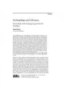
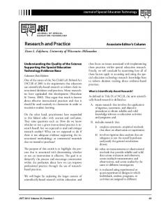
Figure 1. General geometric properties of the double layer barrel vaults.
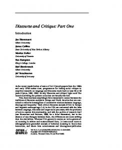
barrel vaults. The length, span and depth of the barrel vaults are kept constant for the barrel vaults and these are 40 m, 30 m and 1.5 m, respectively. Fig 1 shows the configuration of the selected barrel vaults. The connections of the elements of the barrel vaults are taken as pin-jointed. Two types of supports are employed for the barrel vaults, namely, hinge supports and roller supports. The hinge supports are used for the joints along the longitudinal edges of all the barrel vaults and the roller supports are employed for the joints along the gable ends of some of the barrel vaults. So, there are two supports conditions for each barrel vault, that is, support conditions A and support conditions B, Fig 2. The elements of the barrel vaults are sized for the combination of dead load and snow
(a) support conditions A
loads. Two types of snow loading, i.e., symmetric and asymmetric loading according to ‘Eurocode 1: Part 2.3, Action on Structures- Snow loads’ is considered. Cross-sections of the elements are hollow circular tubes and the slenderness ratios of the elements are taken as 100. The elements are dimensioned using an allowable stress design code, that is, “BS 449-2: Specifications for the use of steel in Buildings.” The material used for the barrel vaults is steel and the mechanical properties of this steel are as follows: Modulus of elasticity = 2.05*105 N/mm2 Poisson ratio = 0.3 Yield strength = 275 N/mm2 Ultimate strength = 430 N/mm2
3. SELECTED EARTHQUAKES For obtaining a realistic assessment of the behaviour of a specific structure during future earthquakes, the accelerograms should be selected carefully. Choosing a suitable set of accelerograms depends on the types of criteria used for their selection. There are numerous criteria for selecting the accelerograms that are discussed in published books and papers. In the present work, the accelerograms of the earthquakes are selected with the following considerations in mind: The peak ground acceleration PGA is more than 0.3g The peak acceleration to peak velocity ratio (A /V) is in high range The vertical to horizontal peak accelerations ratio AV/AH is high and The soil effect is not considered. l
l
l
(b) support conditions B
Figure 2. Two types of support conditions. 22
l
International Journal of Space Structures Vol. 19 No. 1 2004
Arjang Sadeghi
By considering the above-mentioned criteria, it is assumed that the selected accelerograms will have the representative effects of any expected severe ground motion for the barrel vaults. The reason for ignoring the soil effect is that for the barrel vaults that are among the short period structures, the soil effect is not considerable. The accelerograms of the selected earthquakes and their characteristics are shown in Table 1. As it may be seen from column 4 of Table 1, the peak ground accelerations of the selected accelerograms are varying from a minimum of 0.605g for Loma Prieta earthquake to a maximum of 1.779g for the Northridge earthquake. In dealing with different accelerograms for the analysis of a structure, it is common to scale the accelerograms. Scaling implies the multiplying the whole time history of an accelerogram by a factor to obtain a predetermined PGA. The purpose of scaling an accelerogram is to achieve two aims: To approach a predefined seismic risk, based on the consideration of the seismological risk of a site together with appropriate economical considerations and l
To make the effects of different accelerograms comparable by equalising their peak values. For the purpose of the current work, where there is no specified site and predetermined seismic risk, the average value of PGA’s is chosen as the target PGA. The average value of the selected accelerograms is found to be 0.96g and this is rounded up to 1.0g for convenience. l
4. DYNAMIC CHARACTERISTICS OF THE BARREL VAULTS The dynamic characteristics of the barrel vaults are found using eigenvalue analysis. For this purpose, the analysis package LUSAS is used. The total masses of the barrel vaults are taken the same and corresponding to a dead load of 500 N/m2. The eigenvalue analysis show that the barrel vaults can be classified as low period-structures, see Table 2, since their principal period is less than 0.5 seconds. Also these analysis show that with increase of rise to span ratios, the principal period increases, see Table 2. Another result of these analyses is that the mass participation of the principal mode (1 st mode)
Table 1. Characteristics of the selected earthquakes No
Earthquake
1 2 3 4 5 6 7 8 9 10 11 12
Cape Mendocino, USA, 1992 Chi-Chi, Taiwan, 1999 Coaling, USA, 1983 Gazli, USSR, 1976 Imperial Valley, USA, 1979 Kobe, Japan, 1995 Landers, USA, 1992 Loma Prieta, USA, 1989 Nahanni, Canada, 1985 Northridge, USA, 1994 San Fernando, USA, 1971 Tabas, Iran, 1978
Component
PGA
PGV
L T L T T L L T T L L T
1.497 0.968 0.866 0.718 0.439 0.693 0.785 0.605 1.096 1.779 1.226 0.852
127.4 107.5 42.2 71.6 109.8 68.3 31.9 51.0 46.1 113.6 112.5 121.4
PGD 41.01 18.6 6.14 23.71 65.89 26.65 70.31 11.5 14.58 33.22 35.5 94.58
A/V
Magnitude M
1.18 0.90 2.05 1.0 0.40 1.01 2.46 1.19 2.38 1.57 1.09 0.70
7.1 7.6 5.8 6.8 6.5 6.8 7.3 6.9 6.9 6.7 6.6 7.4
Note: ‘T’ stands for the transverse and ‘L’ stands for the longitudinal components of the earthquakes. Table 2. Periods of the first modes of the barrel vaults with different rise to span ratios in seconds Period (sec) Rise to span ratio Support conditions
0.15
0.30
0.45
Type A Type B
0.155 0.151
0.186 0.175
0.181 0.177
International Journal of Space Structures Vol. 19 No. 1 2004
23
Horizontal Earthquake Loading and Linear/Nonlinear Seismic Behaviour of Double Layer Barrel Vaults
increases with increase of the rise to span ratio of the barrel vaults. However, in spite of the conventional building structures, the principal mode is not necessarily the dominant mode, see Table 3, and in all cases the participation factors are less than 50%. The results of the eigenvalue analysis also show that even considering the first one hundred modes of the barrel vaults the total participation factor is less than 75%.
5. LINEAR DYNAMIC ANALYSIS RESULTS The dynamic analysis of the barrel vaults show that, except for the barrel vaults with rise to span ratio of 0.15 and support conditions A, all the barrel vaults have some elements that endure beyond their compression strength. This means that some of the members of the barrel vaults do buckle under some of the selected scaled earthquakes. Whether the buckling of some elements leads to failure of the barrel vaults will be discussed in Section 7 in this article. However, it is interesting to mention that for the barrel vaults with support conditions A, the buckling members are the web elements. These web elements are located
near the crown line of the barrel vaults. For the barrel vaults with support conditions B, most of the buckling elements belong to the bottom layer meridian elements. These elements are located near the eaves of the barrel vaults. The relevant results are shown for the barrel vaults with rise to span ratio of 0.45 and support conditions A and B in Tables 4 and 5, respectively. It is worth noting that these results are obtained by using the accelerograms scaled to 1.0g. However, the results show that for the support conditions A even the Coaling earthquake with PGA = 0.71g will cause the buckling of some of the elements, while the actual PGA is 0.86g. For the barrel vault with support conditions B the Kobe earthquake with PGA = 0.44g will cause some elements such as 234 buckle, while the actual PGA is 0.69g. So, it can be imagined that real earthquakes will cause the buckling of some of the elements of the barrel vaults.
6. EQUIVALENT STATIC LOADING To obtain equivalent horizontal nodal forces for earthquakes on the barrel vaults, the selected accelerograms are applied at the bases of the barrel vaults. As one may expect, this will make the joints
Table 3. Mass participation factors for the modes of the barrel vaults First mode (%)
Total up to 100th mode (%)
Rise to span ratio
Rise to span ratio
Support conditions
0.15
0.30
0.45
0.15
0.30
0.45
A B
22.7 21.9
38.1 40.0
45.7 47.2
67.6 66.5
70.45 71.8
74.6 73.1
Table 4. Internal forces of the critical members for the barrel vault with rise to span ratio of 0.45 and support conditions A (strength in kN) Element ID 254 255 258 259 293 297 298 299 300
24
Crosssection type 1 5 1 1 1 1 1 1 1
Pa
Pu
FDL
DPa
DPu
FCoaling
50 75 50 50 50 50 50 50 50
85 127.5 85 85 85 85 85 85 85
5.4 13.6 0.8 8.0 5.7 1.5 1.9 3.8 2.3
45.6 61.4 49.2 42 44.3 48.5 48.1 46.2 47.7
79.6 113.9 84.2 77 79.3 83.5 83.1 81.2 82.7
119.5 123.8 143.5 134.3 120.5 131.3 130.1 137.1 126.3
International Journal of Space Structures Vol. 19 No. 1 2004
Arjang Sadeghi
Table 5. Internal forces of the critical members for the barrel vault with rise to span ratio of 0.45 and support conditions B (strength in kN) Element ID 45 66 87 108 138 139 233 234
CrossSection type 1 1 1 1 18 6 18 7
Pa 50 50 50 50 140 80 140 85
Pu
FDL
DPa
DPu
85 85 85 85 238 136 238 144.5
7.6 7.6 7.6 7.6 29.5 13 29 13
42.4 42.4 42.4 42.4 110 67 111 56
77.4 77.4 77.4 77.4 208.5 123 209 131.5
FKobe 218 220 217 208 234 226 229 236
Legend: Pa = allowable compressive strength of element in kN, Pu = ultimate compressive strength of element in kN, FDL = internal force of elements under dead load in kN, DPa = Pa - FDL = reserve of allowable strength in excess of that required for the dead load in kN, DPu = Pu - FDL = reserve of ultimate strength in excess of that required for the dead load kN, FCoaling = internal force of element under horizontal accelerogram of Coaling earthquake in kN and FKobe = internal force of element under horizontal accelerogram of Kobe earthquake in kN. Note: The internal forces of the elements that undergo buckling during the earthquake are shown in larger font.
of a barrel vault to displace and accelerate. The product of the displacements of the joints by their corresponding stiffness constitutes the elastic part of the induced action. The product of the masses at the joints by their induced acceleration constitutes the inertial part of external excitation. Combination of these two effects with the dissipated part of the input action (namely damping effects) equals the total external effects. The combination of the induced forces at all joints in each time step is equal to the base shear of a barrel vault. However, while the total induced base shear by an earthquake can be calculated directly, obtaining the induced forces at the joints of a structure is not directly possible. In this work, the equivalent forces at the joints are obtained by multiplying the masses at the joints by their induced accelerations. However, as it is mentioned before, this only involves the inertial part of the forces and does not represent the total external excitation effects and therefore, they are used for obtaining the pattern of loading. The induced accelerations of the joints are obtained from the results of the linear dynamic analysis of the barrel vaults by LUSAS. The loads are defined in joints of each level. The arrangement of loads per level is shown in Fig 3 for a double layer barrel vault with rise to span ratio of 0.3.
International Journal of Space Structures Vol. 19 No. 1 2004
To establish the pattern of distribution of the lateral equivalent forces for earthquakes, the calculated equivalent forces (or inertial forces) at the levels shown in Fig 3 are normalised with respect to the corresponding calculated base shears. For instance, Figs 4 and 5 show the normalised forces of the selected accelerograms for the barrel vaults with rise to span ratio of 0.3 and support conditions A and B, respectively. In these figures the mean and mean ±s curves are also presented. To have a general idea of pattern of distribution of the forces in the barrel vaults, the mean value curves for all the barrel vaults are combined and for the purpose of obtaining a more generalised curve for the barrel vaults, the mean curve of the mean normalised forces of the barrel vaults is depicted in Fig 6. For purpose of practical uses, a multi-linear curve shown in dashed line, is suggested for the normalised forces in different levels of the barrel vaults. The suggested curve for the distribution of forces across the height of a barrel vault induced by earthquakes, may be defined as follows: For
hi £ 0.3 H
For 0.3 £
Þ
hi < 0.96 Þ H
Fi h = 0.27æ i + 0.2ö è ø Vb H
(1)
Fi = 0.135 Vb
(2)
25
Horizontal Earthquake Loading and Linear/Nonlinear Seismic Behaviour of Double Layer Barrel Vaults
9
10
7
8 6
5
4
3
2
1
HT = 10.5 m
h
0 (a) Nodes and levels of the barrel vault with rise to span ratios of 0.30. Levels
h/HT
10 9 8 7 6
1.0 0.95
5 4
0.57 0.56
3 2
0.32 0.25
0 1
-0.13
0.85 0.80 0.75
(b) Levels and corresponding relative heights for the equivalent forces on the barrel vaults with rise to span ratio of 0.30 (not to scale).
Figure 3. Levels and relative heights of the barrel vaults with rise to span ratio of 0.30.
1 0.9 0.8 0.7
Mean+s
0.6 Mean
h/H
0.5 Mean-s
0.4 0.3 0.2 0.1 0 -0.1 -0.2 -0.2
0
0.2
0.4 Fi / Vb
0.6
0.8
1
Figure 4. Normalised forces in different levels of the barrel vault with rise to span ratio of 0.30 and support conditions A.
26
International Journal of Space Structures Vol. 19 No. 1 2004
Arjang Sadeghi
1 0.9 0.8 0.7 0.6 0.5
Mean+s
h /H
0.4 0.3 0.2 0.1
Mean Mean-s
0 -0.1 -0.2 -0.2
0
0.2
0.4
0.6
0.8
1
Fi / Vb
Figure 5. Normalised forces in different levels of the barrel vault with rise to span ratio of 0.30 and support conditions B.
1 0.9 0.8 0.7 0.6
h/H
0.5 0.4 0.3 0.2 Mean
0.1 0
Suggested curve
-0.1 -0.2 -0.02
0
0.02
0.04
0.06
0.08
0.1
0.12
0.14
0.16
Fi / Vb
Figure 6. Averages of the normalised equivalent forces in different levels of barrel vaults.
International Journal of Space Structures Vol. 19 No. 1 2004
27
Horizontal Earthquake Loading and Linear/Nonlinear Seismic Behaviour of Double Layer Barrel Vaults
For 0.96 £
hi < 1.0 Þ H
Fi h = 1.875æ1.032 - i ö è Vb Hø (3)
Where H is the height of the barrel vault, Vb is the base shear and hi and Fi are the height and lateral force of the level i, respectively. These formulae are useful when the base shear Vb induced by earthquake is known. So, another relation that is worth considering is the relationship between the lateral base shear and the weight and the principal period of the barrel vault. The probable relationship between the actual base shear and the weight of a barrel vault may be introduced as follows: Vb = CH0 ´ Wt
CH 0 = a ´ [ SA(T1 ) / g ]
Vb Wt
(5)
Finally the earthquake-loading coefficient CH 0 is related to the response acceleration of the first mode of
(6)
where a is a coefficient, SA(T1 ) is the response acceleration of an earthquake for the first mode of a barrel vault whose natural period of the first mode is T1 and g is the gravity acceleration. SA( T1 ) can be obtained by using the response spectra of the selected earthquakes by applying the period of the first mode of the barrel vault. Since the corresponding CH 0 for every SA(T1 ) is calculated from Eq 5, then, a can be found readily as:
(4)
where Vb is the actual base shear, CH 0 is the earthquake-loading coefficient and Wt is the total weight of the barrel vault. For the selected barrel vaults and earthquakes, the terms Vb and Wt are known. Therefore, the earthquake-loading coefficient can be easily calculated from: CH0 =
the barrel vault as follows:
a=
CH 0 [ SA(T1 )/ g]
(7)
This implies that, for every single barrel vault, 12 values for a can be found corresponding to 12 accelerograms. These coefficients are shown in Fig 7 for barrel vaults with support conditions A and Fig 8 for barrel vaults with support conditions B. For design purposes, a single quantity that is relatively conservative is chosen for each of the support conditions. Thus: For support conditions A Þ a = 7.5 For support conditions B Þ a = 8.5
12 11 10 Suggested curve
9 8
Alpha
7 Mean+s
6 Mean
5 4
Mean-s
3 2 1 0
0
0.05
0.1
0.15
0.2
0.25
0.3
0.35
0.4
0.45
0.5
H/S
Figure 7. Relationship of parameter a with the rise to span ratio of different barrel vaults with support conditions A. 28
International Journal of Space Structures Vol. 19 No. 1 2004
Arjang Sadeghi
15 14 13 12 11
Suggested curve
10
Alpha
9 8 7
Mean+s
6 5
Mean
4
Mean-s 3 2 1 0 0
0.05
0.1
0.15
0.2
0.25
0.3
0.35
0.4
0.45
0.5
H/S
Figure 8. Relationship of parameter a the rise to span ratio of different barrel vaults with support conditions B.
So, to find the base shear for a barrel vault for an earthquake, the necessary equations are: For support conditions A Vb = 7.5 ´ [ SA(T1 ) / g ] ´ Wt
(9)
7. NONLINEAR BEHAVIOUR OF THE BARREL VAULTS The double layer barrel vaults and most reticular space structures with pin joints are composed of bar elements. Bar elements are straight elements that can carry axial forces only. While, mostly tensile yielding is significant in the behaviour of rigid jointed structures, available literature shows that compressive yielding or buckling is more significant in the behaviour of the pin-jointed space structures. Therefore, a nonlinear analysis of the pin-jointed space structures such as barrel vaults, should consider a suitable model for the behaviour for the elements of the structure, considering both yielding in compression and tension. There have been extensive research on the static and dynamic behaviour of bar elements. International Journal of Space Structures Vol. 19 No. 1 2004
l l
(8)
For support conditions B Vb = 8.5 ´ [ SA(T1 ) / g ] ´ Wt
The main factors affecting the inelastic behaviour of a bar are Yield strength of the material, Slenderness ratio of the element and Probable imperfections in the geometry of the element. The postbuckling behaviour of bar elements plays a key role in the behaviour of a pin jointed system such as a double layer barrel vault especially when the applied loading is of vibrational nature. Loss of compressive capacity of an element causes the reduced compressive load to be compensated by adjacent elements. The adjacent elements that may have not been designed to meet this situation may yield in compression or tension and, consequently, yielding and buckling of more and more elements may occur. The transfer of internal forces from a buckled element to the adjacent elements is called ‘force shedding’ and it has a dynamic nature because it occurs very rapidly. Progressive failure makes the whole structure brittle and this brittleness makes the structure vulnerable to unpredictable loads such as earthquake loading. In the present work, to define the postbuckling behaviour of a bar element the hysteresis loop obtained by Ishikawa et al [7] is used. This hysteresis l
29
Horizontal Earthquake Loading and Linear/Nonlinear Seismic Behaviour of Double Layer Barrel Vaults
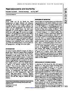
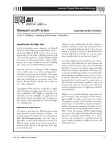
loop is established by incorporating the plastic hinge concept, with the increase of secondary effects due to lateral displacements and plastic axial deformations at a hinge as well as the elastic member shortening. Postbuckling behaviour curve is approximated by a fully quadratic equation in terms of the stress and strain. For a bar with slenderness ratio of 100, the equation for the postbuckling behaviour, as suggested by the Ishikawa model, is as follows: 2
æs ö æs ö æ e öæ s ö + 3.476 11.62 çs ÷ çs ÷ ç e ÷çs ÷ è yø è yø è y øè y ø 2
æ eö æeö + 2.1ç ÷ - 0.09241ç ÷ + 1.189 = 0 è ey ø è ey ø
(10)
where s is the compressive stress in the bar, s y is the yield stress of the material of the bar, e is the axial strain due to s and e y is the yield strain (Fig 9). A performance-based procedure for the nonlinear analysis of the structures is used. This procedure requires the determination of the demand and capacity for a structure. Demand is represented by the earthquake and its effects on a structure. Capacity is the ability of the structure to resist the seismic demand. In order to estimate the structure’s capacity of the
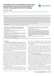
structure beyond the elastic limit, a static nonlinear analysis, so-called pushover analysis, is performed. The capacity curve of the structure is established with static nonlinear analysis and the seismic demand is obtained through linear dynamic analysis. For the static nonlinear analysis the dead load is kept constant and an increasing uniform lateral loading is applied on the joints. The analysis is continued up to a point that the stability of the structure vanishes. The capacity of a barrel vault is taken to be the load that the structure can endure before any joint becomes unstable. The joints and elements identifications are shown in Fig 10. Because of longitudinal symmetry and reducing the analysis task only a symmetric half of the barrel vaults are analysed. Figs 11 to 16 show the horizontal displacements of the joints that become unstable first. The overall behaviour of such a joint is nonlinear and before total instability or collapse, the slope of the displacement curve of a critical joint changes for times. Each change in the behaviour of a critical joint is related to buckling of a member of the barrel vault. For example, Fig 11a shows the response of the barrel vault with rise to span ratio of 0.15 and support conditions A, at node 74 under the combination of dead and horizontal loads. Node 74 is the first node that loses its stability in the barrel vault. In Fig 11a, there are two
Stress ´ 10-8 N/m2
3.0 2.5 2.0 1.5 1.0 0.5
-10
-5
0
5
-0.5
Strain ´ 103
10
-1.0 B A
-1.5 -2.0
Figure 9. Nonlinear behaviour of the Bar element with slenderness ratio of 100.
30
International Journal of Space Structures Vol. 19 No. 1 2004
Arjang Sadeghi
128
129
130
131
132
133
134
135
136
137
118
119
120
121
122
123
124
125
126
127
108
109
110
111
112
113
114
115
116
117
98
99
100
101
102
103
104
105
106
107
88
89
90
91
92
93
94
95
96
97
78
79
80
81
82
83
84
85
86
87
(a) Joints identifications (joints of the top layer are shown more intense) 127
128
116 117 106 95
107
74
86
64 53 43
44
22 11
23 12
1
45
24
3
47
25
26 15
4
49
27
6
63 52
41 30
19 8
73
51
29
84
62
40
18 7
72
50
28
94 83
61
39
17
93
71
115
104 105
82
60
38
16 5
70
48
114
92
136
125 126
103
81
59
37
113
91
69
135 124
102
80
58
36
14
13 2
46
112
90
68
134 123
101
79
57
35
111
89
67
133 122
100
78
56
34
110
88
66
132 121
99
77
55
33
109
87
65
131 120
98
76
54
32
108 97
75
130 119
118
96 85
129
42 31
20 9
21 10
(b) Elements of the top layer Figure 10. Joints and elements identification of half of the double layer barrel vault with square-on square pattern used for the analysis.
International Journal of Space Structures Vol. 19 No. 1 2004
31
Horizontal Earthquake Loading and Linear/Nonlinear Seismic Behaviour of Double Layer Barrel Vaults 232 222
223
213 203
214
176
137
168
148 138
169
149 139
170
150 140
201
181
161
172 162
152 142
153 143
174
164 154
144
193
183 173
163
212
202 192
182
231
221 211
191
171
151 141
210
190
240 230
220
200
180
160
229
209
189
239
219
199
179
159
228
208
188
238
218
198
178
158
227
207
187
237
217
197
177
157
147
216
196 186
236 226
206
167
156 146
215
195
165
235 225
205
185
175
234 224
204
194 184
233
155
145
(c) Elements of the bottom layer 442443446447450 451 454 455 458 459 462 463 466 467 470 471474 475 478479 441 444445448449 452 453 456 457 460 461 464 465 468 469 472473 476477 480 402403406407410 411 414 416 418 419 422 423 426 427 430 431434 435438 439 401404405408409 412 413 416 417 420 421 424 425 428 429 432 433 436 437440 362 363366367 370 371 374 375 378 379 382 383 386 387 390 391 394 395 398399 361 364365368 369 372 373 376 377 380 381 384 385 388 389 392393396397400 322323326327 320 331 334 335 338 339 342 344 346 347 350 351354355358 359 321324325328 329 332 333 336 337 340 341 344 345 348 249 352353356357 360 282283286287 290 291 294 295 298 299 302 303 306 307 310 311314315318 319 281 284285 288289 292 293 296 297 300 301 304 305 308 309 312 313316317320 242243246247 247250 251 254 255 258 259 262 263 266 267 270 271 274275278 279 241 244245248249 252 253 256 257 260 261 264 265 268 269 272273276277280
(d) Elements of the web layer Figure 10. Joints and elements identification of half of the double layer barrel vault with square-on square pattern used for the analysis.
major changes in the response curve, that is, at points C1 and C2 , caused by the buckling of some elements in the barrel vault. Also, the collapse point of the barrel vault, that is, point C3, is shown in Fig 7.11a. At point C3 node 74 snaps and the barrel vault loses its stability and cannot bear more loads. Fig 7.11b shows the axial force changes for a buckled element, that is, element 32
238. In this figure, the axial force in element 238 increases up to a point H (at point G another element buckles and the slope of the response curve for the element changes but it can still carry more load. After point H, element 238 buckles and cannot carry more load. This causes the increasing external loads to be distributed amongst other elements. However, at point International Journal of Space Structures Vol. 19 No. 1 2004
Arjang Sadeghi
0.016 Overall collapse
C3
0.0155 0.015 0.0145
C2
0.014 First buckling
0.0135
Displacement m
Second buckling
0.013
C1
0.0125
-1750
-1700
-1650
-1600
-1550
-1500
-1450
-1400
0.012 -1350
Horizontal base shear kN (a) Displacement of node 74 vs horizontal base shear Horizontal base shear kN -1700
-1650
-1715
-1730 L
-1600
-1550
-1500
-1450
-1400
-118
-1700 -127.2
-120
-127.4 K
-1350 -116
-122
-127.6
-124
Axial force kN
-1750
-126
L
H
K
G
(b) Axial force of element 238 vs horizontal base shear
-128
Figure 11. Critical responses of the barrel vault with rise to span ratio of 0.15 and support conditions A for the horizontal pushover analysis.
K, element 238 loses part of its strength. This causes the lost capacity to be provided by the to other elements. This redirection has a dynamic nature. This effect is shown in the final part of the response curve as part KL. The lost capacity of an element should be carried by the other elements and if they have no extra reserve capacity, the structure will collapse. The collapse occurs at point C3 of Fig 7.11a or point L in Fig 7.11b. Actually, there are other minor changes of the slope in the response curve. However, for clarity they are not shown. Referring to Fig 7.11a, it should be mentioned that, the point C1, C2 International Journal of Space Structures Vol. 19 No. 1 2004
and C3 on the response curve are relatively close to each other. To wit, the load carried by the structure at point C1 is over 1500 kN and the collapse load is over 1700 kN. The same situation prevails in relation to Figs 12 to 16. This means that the barrel vaults are relatively brittle rather than being ductile. Therefore, the reduction factor used for assessing the equivalent earthquake loading for the ordinary structures should not be employed for the barrel vaults and, in fact, the barrel vaults should be designed elastically according to an acceptable risk level. 33
Horizontal Earthquake Loading and Linear/Nonlinear Seismic Behaviour of Double Layer Barrel Vaults
0.01 Overall collapse
C3
0.009 Second buckling
C2 C1
0.007
First buckling
0.006
Displacement m
0.008
0.005 0.004
-1400
-1300
-1200
-1100
-1000
-900
-800
-700
-600
0.003 -500
Horizontal base shear kN Displacement of node 92 vs horizontal base shear Figure 12. Critical response of the barrel vault with rise to span ratio of 0.30 and support conditions A for the horizontal pushover analysis.
0.01 Overall collapse
C3
C2
0.008
C1 0.007
Second buckling 0.006
Displacement m
0.009
First buckling 0.005
-1200
-1100
-1000
-900
-800
-700
0.004 -600
Horizontal base shear kN Displacement of node 92 vs horizontal base shear Figure 13. Critical response of the barrel vault with rise to span ratio of 0.45 and support conditions A for the horizontal pushover analysis.
34
International Journal of Space Structures Vol. 19 No. 1 2004
Arjang Sadeghi
0.015
C4
Overall collapse 0.014
C2
0.013 Third buckling
C1
0.012 0.011
Second buckling
0.01 First buckling
0.009
Displacement m
C3
0.008 0.007
-1500
-1400
-1300
-1200
-1100
-1000
-900
-800
-700
0.006 -600
Horizontal base shear kN Displacement of node 19 vs horizontal base shear Figure 14. Critical response of the barrel vault with rise to span ratio of 0.15 and support conditions B for the horizontal pushover analysis.
0.04
C3
Overall collapse
C2
0.035
C1
0.03 0.025
Second buckling
0.02 0.015
Displacement m
First buckling
0.01 0.005 0 -800
-700
-600
-500
-400
-300
-200
-100
0
Horizontal base shear kN Displacement of node 19 vs horizontal base shear Figure 15. Critical response of the barrel vault with rise to span ratio of 0.30 and support conditions B for the horizontal pushover analysis.
International Journal of Space Structures Vol. 19 No. 1 2004
35
Horizontal Earthquake Loading and Linear/Nonlinear Seismic Behaviour of Double Layer Barrel Vaults
0.075
Overall collapse
C3
0.07 C2
0.065 C1
0.06
First buckling 0.055
Displacement m
Second buckling
0.05 0.45 0.04 -500
-480
-460
-440
-420
-400
-380
-360
-340
-320
-300
Horizontal base shear kN Displacement of node 73 vs horizontal base shear Figure 16. Critical response of the barrel vault with rise to span ratio of 0.45 and support conditions B for the horizontal pushover analysis.
8. CONCLUSION 1
2
3
4
The first mode of the barrel vaults is the principal mode, but not the dominant mode. Mass participation factor of the principal mode increases with increase of the rise to span ratio of the barrel vaults. The barrel vaults are vulnerable and may face collapse in the case of encountering a medium to strong ground motion depending on their rise to span ratio and support condition. Collapse of the barrel vaults is due to the progressive failure caused by the successive buckling of the elements. The barrel vaults show brittle behaviour and should be designed elastically. Some formulae for the assessment of earthquake loading and distribution pattern of the loading for the barrel vaults are presented.
REFERENCES
[1] Kawaguchi, K., (1997) “A report on large roof structures damaged by the great Hanshin-Awaji earthquake” Int. Jor. Of Space Structures, 12, (384). [2] Kawaguchi, K., and Hangai, Y., (1995) “Report on spatial structures damaged by the 1995 great Hanshin earthquake,” Bull. ERS, No. 28. [3] Kuneida, H., Manda, T., and Kitamura, K., “Vibrational characteristics of really existing cylindrical roof structures,” Sixth Asian Pacific Conference on Shell and Spatial Structures, Seoul, Korea, 16-18 October, 2000.
36
[4] Lan, T. T., and Qian, R., (1996) “Analysis of the failure of a space truss subjected to earthquake” Proc. Of AsiaPacific Conf. On Shell and Spatial Structures, Beijing, China. [5] Ishikawa, K., and Kato, S., (1993a) “Earthquake resistant capacity and collapse mechanism of dynamic buckling in double layer lattice domes under vertical motions” Proc. Of Seiken-IASS Symp. Of non-linear analysis and design for shell and spatial structures, Tokyo, Japan. [6] Ishikawa, K., and Kato, S., (1993b) “Dynamic buckling behaviour of single and double layer lattice domes due to vertical earthquakes motions” 4th International Cont. on Space Structures, Guildford, UK. [7] Ishikawa, K., and Kato, S., (1997a) “Elastic-Plastic dynamic buckling analysis of reticular domes subjected to earthquake motion” Int. Jour. Of Space Structures, 12, (3 & 4). [8] Ishikawa, K., and Kato, S., (1997b) “Effect of unbalanced mass distribution on vertical earth quake resistant capacity of double layer lattice dome” Proc. of the IASS International Symposium, 97 on Shell & Spatial Structures, Singapore. [9] Ishikawa, K., Okubo, S., Hiyama, Y., and Kato, S. “Evaluation Method for Predicting Dynamic Collapse of Double Layer Latticed Space Truss Structures due to Earthquake Motion” Int. Jour. Of Space Structures, Vol. 15, Nos. 3 & 4, 2000. [10] Kato, S., and Ishikawa, K. (1984) “Materially non-linear dynamic stability if trussed beams of long span due to vertical earthquake motions” 4th Int. Conf. on Applied Numerical Modelling, Tainan, Taiwan. [11] Kato, S., and Ishikawa, K. (1986) “Materially non-linear stability of a double layer grid due to vertical earthquake motions” Shells, Membranes and Space Frames, Proc. Of IASS Symposium, Osaka, Vol. 3, Ed. Heki. International Journal of Space Structures Vol. 19 No. 1 2004
Arjang Sadeghi
[12] Kato, S., and Ishikawa, K. (1993) “Earthquake resistant capacity and collapse mechanism of dynamic buckling in double layer latticed domes under vertical motions” Proc. Of Seiken-IASS Symp. Of Non-linear analysis and design for shell and spatial structures, Tokyo, Japan. [13] Kato, S., Konishi, Y. and Nakazawa, S., (2000a) “Earthquake Response of a Trussed Girder Supported by Two Columns with Different Characteristics,” Sixth Asian Pacific Conference on Shell and Spatial Structures, Seoul, Korea, 16-18 October. [14] Kato, S., Nakazawa, S. and Niho, Y., (2000b) “Seismic Design Method of Single Layer Reticular Domes with
International Journal of Space Structures Vol. 19 No. 1 2004
Braces Subjected to sever Earthquake Motions,” Sixth Asian Pacific Conference on Shell and Spatial Structures, Seoul, Korea, 16-18 October. [15] Kato, S., Shomura, M., Mujaiyama, Y, Mutoh, I. and Kubota, R., (1996) “Dynamic response and collapse acceleration of single layer reticulated domes under earthquake motions.” [16] Kato, S., Ueki, T., and Mukaiyama, Y., (1997) “Study of dynamic collapse of single layer reticular domes subjected to earthquake motion,” Int. Jour. Of Space Structures, 12, (3 & 4).
37