DaVinci™ Ease of Use Series. HOW TO FLASH U-BOOT ON DAVINCI™ EVM.
OVERVIEW. The DaVinci EVM contains two types of Flash memories: NOR and ...
DaVinci™ Ease of Use Series
HOW TO FLASH U-BOOT ON DAVINCI™ EVM OVERVIEW The DaVinci EVM contains two types of Flash memories: NOR and NAND Flash. The 16MB NOR flash memory is connected to EMIFA via a 16-bit data bus. The 64MB NAND flash memory is also connected to EMIFA but only to 8 data lines of the data bus. For more information such as Flash memory part number, etc. consult Spectrum Digital’s DaVinci-DM644x Evaluation Module Technical Reference document. Currently, two methods of flashing are supported. The first one needs TI Code Composer Studio (CCS) and a compatible JTAG emulator. This is needed if the NOR or NAND Flash memories on the EVM have not been initialized with any bootloader. The second method uses U-Boot to flash another version of U-Boot provided that a working version is already flashed on the board. METHOD I - USING CODE COMPOSER STUDIO Note: these instructions assume that CCS has been configured and tested with a JTAG emulator that works with the DaVinci Evaluation Module. PART A – LOADING U-BOOT TO DVEVM NOR FLASH MEMORY SOFTWARE REQUIRED: - U-Boot image (e.g. file u-boot-567-nor.bin) - File flashwriter_nor.out for NOR - Code Composer Studio (CCS) version 3.2 or newer - DaVinci EVM compatible emulator driver for CCS - Serial terminal application such as HyperTerminal, TeraTerm for MSWindows™ and Minicom or C-Kermit for Linux. HARDWARE SETUP REQUIRED: - JTAG Emulator connected to DaVinci EVM - Connect included RS323 serial cable to “COM1” port of the PC workstation and “UART0” port of the EVM. The terminal emulation software setup is 115200 baud, 8-bit data, no parity, one stop bit and no flow control. - Inspect jumper J4 labeled “CS2 SELECT” and make sure “FLASH” is selected. - Make sure the red S3 switch DIP positions 1 and 2 are set to ON FLASHING INSTRUCTIONS: 1) Start CCS and load flashwriter_nor.out: Open the TMS470 (ARM-side) CCS debugger. From the menu, click on FileÆLoad Program and open the flashwriter_nor.out image as in the following figure:
Rev 0.3 3/28/2006
-1-
DaVinci™ Ease of Use Series
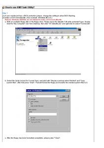
2) Load u-boot: -
-
Run flashwriter_nor.out by either clicking DebugÆRun or hit the F5 key. A dialog box will show to ask for the u-boot filename. Enter the local Windows path to the u-boot file, such as “c:\temp\u-boot-567nor.bin”. It will now ask you for a second parameter, the offset. Enter 0 and press return. Another dialog box will open to ask whether a “global erase” of the 16MB NOR is wanted. If you have previously initialized the old version of U-Boot with parameters and want to keep them, enter “n” for No, otherwise “y” for Yes.
The process may take several minutes. To verify, here’s CCS screen after successful completion:
Rev 0.3 3/28/2006
-2-
DaVinci™ Ease of Use Series
3 ) Verify that U-Boot is working You can now turn off the board and remove the JTAG cable. Make sure a RS232 cable is attached from the board to COM1 of a PC with a terminal emulation program such as Microsoft WindowsXP™ HyperTerminal or Tera Term. The terminal application settings should be set for 115200 baud rate, 8-bit data, one stop bit, no parity and no flow control. Make sure that the board is not turned on. Set the red switch in the middle of the board (S3) to 10111 11110 (1=ON, 0=OFF), check to make sure J4 is selecting FLASH and turn on the board. You should now be greeted with a u-boot prompt on your serial terminal console as below. Note: the “Warning – bad CRC …” can be ignored. It will no longer appear once the uboot parameters are initialized and stored with the “saveenv” command.
Rev 0.3 3/28/2006
-3-
DaVinci™ Ease of Use Series
Rev 0.3 3/28/2006
-4-
DaVinci™ Ease of Use Series PART B – LOADING U-BOOT TO DVEVM NAND FLASH MEMORY SOFTWARE REQUIRED: -
U-Boot image for NAND (e.g. file u-boot-567-nand.bin) File flashwriter_nand.out for NAND File ubl_nand.bin for NAND Code Composer Studio (CCS) version 3.2 or higher DaVinci EVM compatible emulator driver for CCS Serial terminal application such as HyperTerminal, TeraTerm for MSWindows™ and Minicom or C-Kermit for Linux.
HARDWARE SETUP REQUIRED: - JTAG Emulator connected to DaVinci EVM - Connect included RS323 serial cable to “COM1” port of the PC workstation and “UART0” port of the EVM. The terminal emulation software setup is 115200 baud, 8-bit data, no parity, one stop bit and no flow control. - Make sure the red S3 switch DIP positions 1 and 2 are set to ON - Inspect jumper J4 labeled “CS2 SELECT” and make sure “NAND” is selected. FLASHING INSTRUCTIONS: 1) Flashing ubl_nand.bin and u-boot-567-nand.bin: Following is the step-by-step sequence to program these 2 binaries to NAND flash on the DVEVM. A CCS screen shot is included below as an illustration (the user input is displayed in blue by CCS). -
-
Start CCS and open the TMS470 (ARM-side) CCS debugger. From the menu, click on FileÆLoad Program and select the file “flashwriter_nand.out”. Hit F5 to run program. A dialog box will open to ask for a file name. Enter the path for ubl_nand.bin, for example “c:\temp\ubl_nand.bin”, and hit Enter. Another dialog box will open. The message “Burn Block Offset” will show in CCS. Enter “1”. Another dialog box will open this time to ask whether we want to globally erase the flash. Enter “y” for “yes”. The NAND flash memory will get erased and formatted.
Now to load u-boot, perform the following steps - From the CCS menu, click on FileÆReload Program and reload the file “flashwriter_nand.out” - Hit F5 to run program. A dialog box will open asking to enter a file name. - Enter the path for the nand version of u-boot, for example u-boot-567-nand.bin and hit Enter. Another dialog box will open to enter the offset. - Enter an offset of “6”. Another dialog box will open to ask for global erase. - Enter “n” this time for “No”. - At the new dialog box, enter “0x81080000” for the Application Entry Point.
Rev 0.3 3/28/2006
-5-
DaVinci™ Ease of Use Series -
At the new dialog box, enter “0x81080000” for the Application Load Address. If the operation is successful, CCS should output as the screen shot in about a couple of minutes.
3 ) Verify that U-Boot is working You can now turn off the board and remove the JTAG cable. Make sure a RS232 cable is attached from the board to COM1 of a PC with a terminal emulation program such as Microsoft WindowsXP™ HyperTerminal or Tera Term. The terminal application settings should be set for 115200 baud rate, 8-bit data, one stop bit, no parity and no flow control. Make sure the board is not turned on.
Rev 0.3 3/28/2006
-6-
DaVinci™ Ease of Use Series Set the red switch in the middle of the board (S3) to 00001 11110 (1=ON, 0=OFF), check to make sure J4 is selecting NAND and turn on the board. You should now be greeted with a u-boot prompt on your serial terminal console as below. Note: the “Warning – bad CRC …” can be ignored. It will no longer appear once the uboot parameters are initialized and stored with the “saveenv” command.
Rev 0.3 3/28/2006
-7-
DaVinci™ Ease of Use Series II USING U-BOOT TO REFLASH U-Boot can support reflashing its own image. IMPORTANT: IF THIS STEP FAILS, YOU MUST USE METHOD ONE (CCS) TO REFLASH. SOFTWARE REQUIRED: -
U-Boot image Serial terminal application such as HyperTerminal, TeraTerm for MSWindows™ and Minicom, C-Kermit for Linux. Linux PC needs tftpserver installed
HARDWARE SETUP REQUIRED: - Connect included RS323 serial cable to COM1 port of the PC workstation and UART0 port of the EVM. FLASHING INSTRUCTIONS:
Following are the instructions:
Power cycle the board to verify that the recently flashed U-Boot is working by inspecting the build date on the serial terminal console output.
Rev 0.3 3/28/2006
-8-


![INFORMATION - EVM World [PDF]](https://m.moam.info/img/260x300/information-evm-world-pdf_650617f6098a9e6a288b45b9.jpg)


![[PDF] The Definitive Guide to Editing with DaVinci ... - Google Sites](https://m.moam.info/img/260x300/pdf-the-definitive-guide-to-editing-with-davinci-g_6477fd60097c47a9708c53e5.jpg)