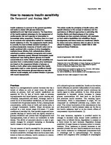
HOW TO MEASURE CAPACITANCE EQUAL TO THE EARTH? O. Vdovin, V. Martynyuk and G. Gordienko Electronics Department Technological University of Podillya, Khmelnitsky, Ukraine Abstract: The report is devoted to measurement problems of the capacitor parameters for superhigh capacitances (1F-200F). The models of such objects are proposed. The mechanism of influence on the measurement result is determined for additional parameters. These parameters are the absorption capacitance CA and the absorption resistance RA, the leakage resistance RL and the active serial resistance R. Besides, the measuring structures that make it possible to take into consideration the influence of additional parameters are proposed. Moreover, the accuracy of the proposed measuring structures is defined with the direct current and the alternating current. Keywords: superhigh capacitance, absorption capacitance, leakage resistance. In real time many scientific organizations and institutes design new components with a superhigh capacitance (up 1F to 200F) [1]. For example, “Kation” Company (Khmelnitskiy, Ukraine) manufactures new type of the components with the capacitance 30F and the nominal voltage 3V, so called “super capacitor”. But in fact, these objects are not classical capacitors, because they have a large active serial resistance R. It means that these objects have a very large dielectric dissipation factor, because their reactive resistance XC is less than 0.001Om. As for classical capacitors, they have a very small dielectric dissipation factor in comparison with these objects. Therefore, the standard methods can not be used for measuring such objects. Basically, the standard analyzers do not guarantee the accuracy if the dielectric dissipation factor tg is more than 0.1. Besides, the capacitance measures are absent for capacitance more than 0.01F. Such objects are used, as a reserve source of current or voltage for the electronics devices with low power consumption. These objects are able to accumulate the electrical energy and then to return it rapidly. Besides, they are used as a smoother for voltage regulators. The researches show that the model of these objects differs from the capacitor model by the existence of additional parameters, such as the absorption capacitance C A and the absorption resistance RA. Besides, the model contains the parameters of the capacitor model, such as the leakage resistance RL and the active serial resistance R. By analyzing the application of these objects, we come to the conclusion that for measuring their capacitance, it is necessary to perform the measurements with a direct current and an alternating current, because the standardization of measurement methods for such objects is absent. The performed experiments show that the direct current capacitance (so called “slow capacitance”) is much more than the alternating current capacitance (so called “fast capacitance”). It means that the “slow capacitance” contains both types of capacitance: the main capacitance C and the absorption capacitance CA. As for the “fast capacitance”, it contains only the main capacitance C, because the absorption resistance RA is much more than the active resistance R. By proceeding from these suppositions, we propose two measurement models. Such models are the measurement direct current model and the measurement alternating current model. The measurement direct current model uses the stable current source J and it is shown in Fig.1.
Figure 1. The model of charge superhigh capacitance with the fixed direct current.
The analysis of this model makes it possible to define the measurement accuracy for capacitance on account of additional parameters that is shown in Fig.1. The voltage U(t) is defined by the expression: G
t J J U (t ) U С (t ) e C , GP GL G G A
(1)
where GP=1/RP, GL=1/RL, G=1/R, and GA=1/RA are the corresponding conductances. The existing capacitance analyzers do not consider these additional parameters. They use the simple capacitor model that is shown in Fig.2.
Figure 2. The model of charge superhigh capacitance without the additional parameters. In this case the voltage U(t) is defined by the expression:
U (t ) U C (t )
Jt , C
(2)
where J is the current of the source (J=const). By comparing the expression (1) with expression (2), we come to the conclusion that the standard capacitance analyzers have a method error. Therefore, the accuracy of these capacitance analyzers is determined by the equation:
G
t U (t ) U C (t ) C C e C U C (t ) GP t (GL G G A )t
(3)
The standard fundamental charge/discharge method makes it possible to measure the “slow capacitance” of such objects with the fixed direct current. But if these objects are used as a smoother for voltage regulators, it is necessary to measure such objects with an alternating current. In this case the measurement capacitance is much less than the direct current capacitance, because we measure only the “fast capacitance”. Among the existing LCR meters only the analyzers, which use the measuring methods with an alternating current are of the greatest accuracy. The best samples of such analyzers are the precision LCR meters of the leading companies in world, such as General Radio (series 1692 and 1693), Wyne Kerr (series 6425) and Hewlett Packard (series HP4274A, H275A and HP4284A, 4285A) [2]. By analyzing the parameters and the characteristics of these analyzers relative to the measurements of the capacitance, we come to the conclusion that for a small and middle capacitances (up to 100mF), these analyzers have the high accuracy (nearly 0.05%) but for measuring the superhigh capacitances (over 1F) the measurement accuracy decreases rapidly. So these measurements are only a valuation. Moreover, these objects are not traditional capacitors. The active resistance R of such objects is up 20 to 50 times more than reactive resistance Xc. However, the standard analyzers guarantee the measurement of capacitance with the dielectric dissipation factor less than 0.1. To determine and to analyze the influence of the factors that decrease the measurement accuracy for the superhigh capacitances with an alternating current, it is necessary to analyze the measurement model of these objects with an alternating current. The measurement alternating current model consists of the measuring object with the unknown complex impedance Zx , the precision reference active resistance R0, which is in series with measuring object and the voltage sine generator G. This model is shown in Fig.3.
Figure 3. The measurement alternating current model for measuring of the superhigh capacitance. In general, let’s assume that the object consists of the serial active resistance R and the reactive resistance X, wich are shown in Fig.3b. According to circuit theory, the relation of the complex voltage relation of the complex impedances.
U G and U X are equal to the
U G R0 Z X ZX U X
(4)
Hence it follows that the complex impedance ZX of the measurement object is: ZX
U X R0 U G U X
(5)
The complex impedance ZX and complex voltages can be writen in the algebraical form:
Z X R jX U G U GP jU GQ , U U jU XP XQ X
(6)
where R is the active resistance; X is the reactive resistance; U GP and UXP are the in-phase parts of the voltages; UGQ and UXQ are the quadrature-phase parts of the voltages. The quantities from equations (6) can be substituted in to the equation (5). In this case, we obtain the next equation:
R jX
(U XP jU XQ ) R0 (U GP jU GQ ) (U XP jU XQ )
(7)
Hence if follows that active resistance and reactive resistance of the measurement object can be determined as:
R X
U 0 PU XP U 0QU XQ U 02P U 02Q
R0
(8)
1 U 0 PU XQ U 0QU XP R0 , C U 02P U 02Q
(9)
where U0P=UGP-UXP, U0Q=UGQ-UXQ. Thence the capacitance of the measurement object is:
C
U 02P U 02Q
R0 (U 0 PU XQ U 0QU XP )
,
(10)
where is an angular frequency of the sine voltage UG. By analyzing the mathematical model (10), we come to the conclusion that the accuracy depends on the accuracy of the precision reference active resistance R 0 firstly. Ensuring accuracy R0 by means of the modern element base is not a very difficult task because precision resisters with accuracy of 0.01% and more exist. The next parameter, which influences the accuracy of measuring capacitance, is an angular frequency of the signal generator. By considering that =2f, the frequency, f, can be measured by
means of converting it to the time interval. Hence it follows that angular frequency can be measured with high accuracy. The main problem is ensuring the accuracy of measuring the in phase parts and quadrature-phase parts of the voltage according to mathematical model (10). It means that the solution of this problem depends on the structure and the accuracy of the vector voltmeter. It will determine the digital equivalent of the specified voltages to provide the microprocessor system with necessary data for computing the capacitance determined by the mathematical model (10). The structure of the superhigh capacitance analyzer is shown in Fig.4.
Figure 4. The measurement structure of superhigh capacitance analyzer. The analyzer consists of the voltage sine generator G, the precision active resistance R 0, the switches K1 and K2, the measurement amplifier A1, the phase shifter (=90), the squarings, the phase-lock detector, the integrator, the analog to digital converter (ADC) and the microcomputer. By analyzing this measurement structure of superhigh capacitance analyzer and mathematical model (10), we come to the conclusion that the accuracy of this structure is determined by the accuracy of measuring the in-phase voltages and the quadrature-phase voltages. But in fact, if the measurement channel does not insert the additional phase shift in the voltage U0, we must measure only the voltage U0P, because the voltage U0Q=0. Hence it follows that the superhigh capacitance, in this case, is determined by the expression:
C
U 0P R0U XQ
(11)
The analysis of this expression shows that the accuracy of measuring is determined by the next equation:
C C0 P C XQ
C C U 0 P U XQ U 0 P U XQ
(12)
To define this accuracy, it is necessary to determine the influence of both parameters. In general, the accuracies C0P and CXQ depend on the accuracy of the A/D converter. Besides, as for the accuracy CXQ, it is determined by the accuracy of phase shifter also. So if the phase shifter has the angular error that the phase angle is:
90 According to the vector diagram of voltages that is shown in Fig.5, the accuracy of UXQ is determined by:
(13)
U XQ U XP tg
(14)
Figure 5. The vector diagram of voltages. Hence if follows that the accuracy CXQ is defined by the expression:
C XQ where
tg
U 0U XP tg U0 tg tg , 2 R0U XQ R0U XQ
(15)
r U XP - the dielectric dissipation factor. x U XQ
Therefore, a relative error of measuring is written as:
XQ
C XQ tg tg C
(16)
By analyzing this equation, we come to the conclusion that a relative error of measuring for the capacitance increases rapidly when the object has a large dielectric dissipation factor and the phase shifter has the angular error .
Conclusions: 1. For objects with a superhigh capacitance it is necessary to measure the “slow capacitance” and the “fast capacitance”. 2. For the capacitance analyzers with direct current it is necessary to improve the structures according to the additional parameters of objects with a superhigh capacitance. 3. For the capacitance analyzers with alternating current it is necessary to work out the problem of a measurement check in a capacitance range over 100mF. 4. The authors designed a measurement check of capacitance analyzers with alternating current by means of the transformer impedance measure, which uses the basic standard measure 1000F. This measure allows performing the measurement check of capacitance analyzers from up to15F. 5. The authors designed the capacitance analyzer with alternating current, which allows measuring the superhigh capacitance up to 100F with the dielectric dissipation factor of dozens of measurement units. REFERENCES [1] M. Kiuichi, S. Kei, S. Hiroyoki, FS-type SUPERCAPs, NEC Technological Journal 36 (12) (1983) 127-129. [2] HP Test & Measurement Catalog (5091-3000EE), 1992. AUTHORS: Ass. Prof. Dr. Olexandr VDOVIN, Ass. Prof. Dr. Valeriy MARTYNYUK, Univ. Prof. Grigory GORDIENKO, Electronics Department, Technological University of Podillya, 11 Institutskaya str. 29016, Khmelnitsky, Ukraine, Phone: (03822) 728-874, Fax: (03822) 232-65, E-Mail:
[email protected]