HRTF SIMULATIONS THROUGH ACOUSTIC RAYTRACING Niklas R¨ober, Sven Andres and Maic Masuch Department of Simulation and Graphics, School of Computing Science, Otto-von-Guericke-University Magdeburg, Germany ABSTRACT The determination of individual head-related transfer functions (HRTF) for 3D sound rendering remains a challenging task. The measurement of individual HRTFs is not practical, due to the requirements of heavy and expensive equipment as well as an anechoic chamber for the measurement itself. Some techniques have been proposed to individualize general HRTFs, but still many restrictions apply. This work describes an alternative approach for measuring individual HRTFs through acoustic raytracing. We designed a system that is able to load individual 3D meshes and perform an HRIR simulation. Although, we mainly focus on spectral reflections, we also simulate frequency dependent diffraction, absorption and transmission effects. 1. INTRODUCTION The human hearing system has remarkable abilities in identifying sound source positions in 3D space. Although this process is often aided by visual guidance, knowledge and other sensory input, it is based on just two acoustic signals (two ears), and allows an accuracy of up to three degrees for directional positioning [1]. Virtual sound rendering can be separated into two main groups: the simulation of room acoustics and 3D sound synthesis. Room acoustics add reverb and delay effects to an acoustic signal to model different environments. 3D sound synthesis uses perceptional hearing cues to spatialize monaural sound sources in 3D space. The main perceptional cues for 3D hearing are interaural time- and level differences, spectral-, distance- and dynamic cues [2]. Interaural differences model the signal changes in time and intensity, that are caused by the ears position and shadowing effects of the head and torso. Spectral cues aid especially in the localization of sounds in the median plane and are related to spectral changes introduced by the interaction of sound with the outer ears at high frequencies, and at low frequencies by the torso and other body parts. The distance is described by changes in loudness and often also by spectral
[email protected]
changes due to atmospheric diffusion and absorption. An additional effect that supports 3D sound perception are dynamic cues, caused by either or both sound source or head and body movement. All acoustic cues that are used to decode spatial information are directly encoded in the binaural signal. The overall effect of the human body is specified by the head-related transfer function (HRTF) and incorporates interaural differences as well as spectral cues and is therefore very effective for modelling 3D virtual sound sources. The HRTF is a function of direction, distance and frequency and usually measured in an anechoic environment using elaborate and expensive equipment [3]. It is defined as the Fourier transform of the actually measured head-related impulse response (HRIR) and individual for every person [4]. Recent research has focused on techniques to design generalized HRTFs, but also to individualize measured HRTFs to fit the listeners needs [5], [6]. But these techniques still often cause front/back confusions and are far away from the accuracy of individual HRTFs. Numerical simulations have been employed to calculate the HRIR through FEM and BEM techniques, but these are computationally expensive and can not be solved for the entire spectrum [7], [8]. In this work we describe a novel approach to determine HRTFs by using acoustic raytracing. We used an existing raytracing program (POVray) and extended it with audio raytracing capabilities [9]. These include material effects like absorption and transmission, but also frequency dependent reflections and diffraction. The HRTF are measured by simulating an impulse response that is recorded by a semi-spherical surface, placed inside the ear canal of a 3D mesh. This mesh can be changed easily and makes this technique well suited to measure individual HRTF. This research is work in progress, but we have preliminary results that are very promising. The paper is organized as follows: After this introduction we discuss the principles of acoustic raytracing and focus here on the impulse response raytracing. The following section 3 presents the final system, which is can be used to determine individual HRTF. Section 4 shows some results and discusses issues of accuracy and efficiency. Finally, Section 5 summarizes the work and states future directions for improvements.
2. ACOUSTIC RAYTRACING Sound and light are in general of different nature and perceived by two distinct senses. However, in terms of propagation and the interaction with objects, there are some similarities: Both propagate as wave, of which sound waves represent real mechanical, longitudinal waves of varying pressure with a wide spectrum of wavelength. As the wavelength is much longer, diffraction and interference effects are much more prominent. Other effects like absorption, transmission, diffusion, reflection and refraction are similar to light and depend on the wavelength and the objects material properties. For high frequencies with wavelength much shorter than any objects size, sound waves can be considered as rays and computer graphics techniques are applicable [10].
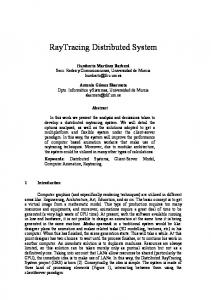
Fig. 1. Acoustic Raytracing Several areas use these similarities and employ methods from computer graphics to simulate the propagation of sound waves. One of these is the area of room acoustics and the computation of sound wave behavior in enclosed spaces. Depending on the room size and the sounds wavelength, two different approaches are considered: For low frequencies, where wave-based effects can not be ignored, the propagation is simulated through time- and frequency difference models, like waveguide meshes [11], or numerical solutions using FEM or BEM [8]. With higher frequencies, sound waves can be approximated as rays, and therefore ray-, cone- or beam tracing techniques are employed to simulate wave propagation [10], [1]. In most cases, this only includes specular reflections and to some degree absorption due to certain materials. Often these techniques are only used to determine the sounds origin, in which a sound file is afterwards filtered with the appropriate HRTF, opposed to raytracing acoustic data [12]. In the last years, computer graphics hardware has evolved by several magnitudes. As of this amount of processing power, the GPU (graphics processing unit) is used alternatively for a variety of non-graphics calculations, including image analysis, algebra and signal processing [13]. It was employed as general DSP for sound signal processing [14], [15], [16] and as raytracing system to solve basic room acoustics [17]. 2.1. Impulse Response Raytracing HRTFs are measured as impulse responses in which the interaction with the head, the outer ear and the torso modify a
given input signal [18]. In order to employ computer graphics techniques for this simulation, the raytracing approach has to be changed itself to incorporate the signals runtime into the rendering. The final result is not an image, rather a 1D signal, that is recorded over time. Furthermore, the varying influences of the different frequencies have to be considered, and here a direct mapping of the acoustical properties to visual qualities is applicable by assigning colors to certain frequency bands. The lower frequencies (20 Hz - 1,000 Hz) are represented by the red channel, the middle frequencies (1,000 Hz 8,000 Hz) by green and the higher frequencies (5,000 Hz 20,000 Hz) are mapped to the blue component. Although the acoustic raytracing still uses a camera plane, refer to Figures 1 and 2, the processing of the data has changed. Each ray is associated with a color (frequency spectrum) and a time stamp that represents its contribution to the impulse response. Sound waves behave in a similar, but slightly different way, which has to be accounted by the acoustic raytracing. Figure 1 shows an example of the technique as it is implemented. The sound Source emits several white rays (all frequencies) which are traced towards the Receiver. One of these rays (Direct) hits the receiver without getting modified by any object, and therefore is only affected by the signals runtime. Another ray hits the floor and gets partially reflected, as the surface is high frequency (blue) absorbent. Two other rays are diffracted around a box in front of the receiver and are partially received. The raytracing itself runs backwards, in which rays are shot for each pixel from the camera surface into the scene. Compare with Figure 2 that shows the camera hemisphere inside the ear canal.
Fig. 2. Impulse Response Raytracing (Ear) The majority of the localization cues lies in the higher frequency bands. The lower frequencies, with wavelength larger than the heads diameter, are diffracted around the head and arrive at the ears just affected by the air absorption. We modelled this behavior as ambient sound, in which the lower frequency components, eg. the red channel, are directly copied to the impulse response after being changed in amplitude and time, due to transmission effects and signal delay. Although technically not correct, we basically ignore the different wavelengths and treat all sound waves as rays. The specular and diffuse reflections are modelled similar to computer graphics, where the angle of incident equals the angle of reflection. The
interaction of sound rays with scene objects depend on their material specifications, and includes frequency dependent reflections, absorption and transmission. We also simulate diffraction effects by using a multi-sampling approach. Several rays are fired within a small area, and if an edge is detected, an additional sampling point is placed atop of this position and samples the upper hemisphere in the rays normal direction. These results are further affected by a frequency dependent diffraction coefficient, in which higher frequencies (blue) are less bend then the lower ones (red), see Figures 1 and 2.
is not part of the current implementation and remains future work. One limitation of the current system is the simplification to a ray-based approach. Although this limits the technique to a basically non-wave-based propagation and neglects especially the low frequencies, it remains an interesting approach which might aid in the future to the quality of 3D sound perception by using individual HRTFs.
2.2. Implementation The acoustic raytracing as presented in the last section was implemented using the freely available Persistence Of Vision rendering program [9]. The raytracer can still be used to render visual landscapes, but is now also able to compute impulse responses of acoustic simulations. The adaptations to Povray are relatively simple: A sound source is approximated by a point light and the microphone is represented by a hemispherical camera surface. The color represents the different frequency bands and is used to model individual object material specifications for frequency dependent reflection, absorption, transmission and diffraction, see also Figures 1 and 2. The largest changes occurred in the rendering method of Povray, which now holds the data structure to compute the impulse response after the raytracing is completed. The impulse response is the sum of all contributing rays, which are arranged according their time stamp, and is stored on the hard disk in the .wav format. 3. HRTF SIMULATION Based on the impulse response raytracing approach from the last section, we designed an HRIR simulation that can be used to acquire personal HRTFs from geometrical models through acoustic raytracing. This research is work in progress and at the moment employs only one head model. In the future, the system will eventually be extended by a mesh generation tool that uses computer vision techniques to modify the head and the pinna to fit the individual listeners needs. An overview of the system is shown in Figure 3, which looks similar to general HRTF measuring procedures. For the impulse response raytracing, a hemispherical camera surface is placed inside the ear canal and a sound source is positioned at varying angles in a distance of 1.4m, compare also with Figure 2. For each angular position, the acoustic scene is now captured through raytracing and the resulting impulse response computed. So far the raytracing is evoked at every sample point, but as the scene geometry is not changing, the reflection and diffraction rays are always the same, only the lighting (acoustics) changes. A large data structure could hold all the ray information and could be used to determine the changed lighting (acoustic) condition much faster. But this
Fig. 3. HRIR Raytracing Principle.
4. RESULTS AND DISCUSSION As we present work in progress, we only have conducted a few experiments using non-individualized meshes. For the experiments we used a high-resolution mesh from the Viewpoint Catalog (#VP4242) [19]. We experimented with different camera sizes, material properties and raytracing resolutions. Further experiments, especially with real data have to be accomplished to verify and validate the proposed technique. Figure 4 shows two examples, displaying head-related impulse responses, respectively for the horizontal and the median plane.
(a) Horizontal Plane HRIR.
(b) Median Plane HRIR.
Fig. 4. Head-related Impulse Responses. Figure 4(a) shows the horizontal plane, which was measured using an angular difference of 5 degrees, while the median plane, Figure 4(b), was sampled with a resolution of
10 degrees. One clearly sees the main pulses, as well as the pinna, the shoulder and the torso reflections. Both images were generated using a hemispherical camera surface, see Figure 2, and an angular resolution of 3 degrees for raytracing and 5 degrees for the diffraction sampling. Important are the pinna reflections, which translate into notches in the frequency domain. These notches are elevation dependent and considered as the main cue for the perception of elevation [10]. Also, the head shadowing effects can clearly be seen in the horizontal plane, Figure 4(a). We also experimented with auralizations, in which we used the impulse response to convolve anechoic sound files. These first results are very promising, but especially for different elevations not completely convincing. 5. CONCLUSIONS AND FUTURE WORK We have presented an acoustic raytracing approach which is able to perform impulse response measurements based on geometric models. This technique was applied to simulate headrelated impulse responses to model individual HRTFs. For this simulation we focussed on the ray-based simplification for sound wave propagation, but also emulated diffraction end low frequency transmission effects. The first results are very promising and motivate further research in this area. Future work will include both, issues of accuracy and efficiency. A refinement of the technique regarding the acoustic properties is necessary to closer emulate real sound wave propagation, especially for the lower frequency end. A promising approach seems to adopt the BRDF lighting principles towards the ray-based wave propagation. The efficiency of the current implementation is also not optimal, and a ray cache structure along other speedups can be employed to improve the rendering speed. Additionally, the system can be extended to integrate individual pinna meshes and to adjust the head model to fit the listeners needs. This can probably be done through computer vision methods. 6. REFERENCES [1] Durand R. Begault, 3D Sound - For Virtual Reality and Multimedia, NASA Ames Research Center, 2000. [2] Yiteng Arden Huang and Jacob Benesty, Eds., Audio Signal Processing for Next-Generation Multimedia Communication Systems, Springer, 2004. [3] W.G. Gardner and K. Martin, “HRTF Measurements of a KEMAR Dummy-Head Microphone,” Tech. Rep. 280, MIT Media Lab, 1994. [4] E.M. Wenzel, M. Arruda, D.J. Kistler, and F.L. Wightman, “Localization using Nonindividualized Head-related Transfer Functions,” Journal of the Acoustical Society of America, vol. 94, no. 1, pp. 111–123, 1993.
[5] D. N. Zotkin, J. Hwang, R. Duraiswami, and L. S. Davis, “HRTF Personalization using Anthropomentric Measurements,” in 2003 IEEE Workshop on Applications of Signal Processing to Audio and Acoustics, New Paltz, NY, USA, October 2003, pp. 157–160. [6] John F. Richardson and Jerry Kaiwi, “Individualized Head Related Transfer Functions: Generation and Utility of Synthetic 3-D Audio in Simulation,” in The Proceedings of the 2002 Summer Computer Simulation Conference, 2002. [7] Shiro Ise and Makoto Otani, “Real Time Calculation of the Head Related Transfer Function based on the Boundary Element Method,” in Internation Confererence on Auditory Display, Kyoto, Japan, 2002. [8] Y. Kahana, P.A. Nelson, M. Petyt, and S. Choi, “Numerical Modeling of the Transfer Functions of a Dummy-Head and of the external Ear,” in Audio Engineering Society, 16th International Conference, 1999. [9] Persistence of Vision Raytracer Pty. Ltd., “The Persistence of Vision Raytracer,” http://www.povray.org, 2005. [10] Udo Z¨olzer, Ed., DAFX - Digital Audio Effects, John Wiley & Sons, West Sussex, England, 2002. [11] Lauri Savioja and Tapio Lokki, “Digital Waveguide Mesh for Room Acoustic Modelling,” in ACM SIGGRAPH and Eurographics Campfire: Acoustic Rendering for Virtual Environments, Utah, USA, 2001. [12] Wolfgang Mueller and Frank Ullmann, “A Scalable System for 3D Audio Ray Tracing,” in Proceedings of the IEEE International Conference on Multimedia Computing and Systems, 1999, vol. 2, pp. 819–823. [13] GPGPU Community, “General-Purpose Computation Using Graphics Hardware,” http://www.gpgpu.org, 2005. [14] Sean Whalen, “Audio and the Graphics Processing Unit,” Tech. Rep., 2005, http://www.node99.org/ projects/gpuaudio/. [15] BionicFX, “Revolutionary Programming and Innovation uses GPU as Powerful Audio Effect Processor”,” Press Release, 2004, http://www.bionicfx.com/. [16] Emmanuel Gallo and Nicolas Tsingos, “Efficient 3D Audio Processing with the GPU,” in GP2, ACM Workshop on General Purpose Computing on Graphics Processors, 2004. [17] Marcin Jedrzejewski, “Computation of Room Acoustics Using Programmable Video Hardware,” in International Conference on Computer Vision and Graphics, 2004. [18] Phillip C. Brown and Richard O. Duda, “A structural Model for Binaural Sound Synthesis,” IEEE Transactions on Speech and Audio Processing, vol. 6, no. 5, pp. 476–488, September 1998. [19] Digimation Inc., “Premier 3D Model Catalog,” http:// www.digimation.com, 2005.