Jun 25, 2011 ... The HTC temperature controllers are easily configured for any design. Virtually
any type of temperature sensor can be used with the HTC and a.
Low Profile, Efficient Temperature Controllers
e
Pb
GENERAL DESCRIPTION
FEATURES
The advanced and reliable circuitry of the HTC series achieves 0.0009°C temperature stability. Its small, low profile package is ideal for designs with space constraints. The linear, PI control loop offers maximum stability while the bipolar current source has been designed for higher efficiency.
Compact Size - 1.5 and 3.0 A Models Interfaces with Thermistors, IC Sensors, & RTDs Single supply operation +5 V to +12 VDC (contact factory for higher voltage operation) +11 V compliance with +12 V input Stabilities as low as 0.0009°C Temperature Setpoint, Output Current Limit, Sensor Bias, Proportional Gain, and Integrator Time Constant are User Adjustable Monitor outputs for Temperature Setpoint and Actual Temperature Linear Bipolar or Unipolar Output operates thermoelectrics or resistive heaters
The HTC temperature controllers are easily configured for any design. Virtually any type of temperature sensor can be used with the HTC and a built in sensor bias current source simplifies use with resistive temperature sensors. The independently adjustable Proportional Gain (P) and Integrator Time Constant (I) can be modified to optimize temperature overshoot and stability. Other features offer added flexibility. A single resistor sets the maximum output current to your load. Add a diode to operate resistive heaters with a unipolar output current. An onboard reference voltage simplifies potentiometer control of the temperature setpoint. You can also choose to operate remotely with an external setpoint voltage. Two monitor pins provide access to the temperature setpoint voltage and the actual sensor voltage.
RoHS
Compliant
HTC Series
ORDERING INFORMATION Model
Description
HTC1500-62 HTC3000-62 HTC1500 HTC3000 PWRPAK-5V PWRPAK-12V HTCEVAL PCB
1.5 A Temp Controller (for 0.062” board) 3.0 A Temp Controller (for 0.062” board) 1.5 A Temp Controller (for 0.031” board) 3.0 A Temp Controller (for 0.031” board) +5 V @ 8 A Power Supply +12 V @ 3 A Power Supply Evaluation Board, 0.062” thick (Includes HTC Heatsink, and thermal grease)
HTCHTSK THERM-PST
Heatsink for HTC Thermal grease
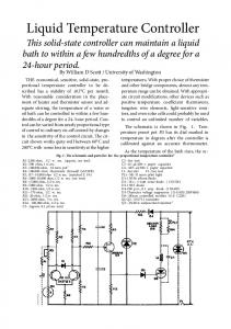
Figure 1 HTC Series Pin-Out, Top View
1 - Limit 2 - Limit + 3 - PID Out 4 - V REF Out 5 - Common 6 - ACT T Monitor 7 - SET T Monitor 8 - SetpointInput 9 - V+ 10 - GND 11 - TEC + 12 - TEC 13 - Sensor + 14 - Sensor 15 - R BIAS + 16 - R BIAS 17 - R PROP+ 18 - R PROP 19 - C INT + 20 - C INT -
HTC Temperature Controller
© 2011
HTC1500-00400-L
www.teamwavelength.com
HTC1500 / HTC3000 TEMPERATURE CONTROLLERS
June, 2011
Figure 2 Quick Connect This diagram shows HTC connections for basic operation. Details for each component are on pages 7 & 8. Set Current Limit with trimpot or resistor.
Operate from single +5 V to +12 VDC power supply V+ (+5 V to +12 V)
Measure Temperature Setpoint & Actual Temperature
9
+ -
External Voltmeter
}
GND (for pin 9)
6
ACT T Monitor
7
SET T Monitor
8
RT
4
Set Proportional Gain between 1 and 100. Fixed, Metal Film 1 M:
LIMIT -
10
5
Control Temperature Setpoint with resistor, trimpot, or external voltage.
V+
PID OUT TEC +
Common
TEC -
3.675 V REF OUT
18 RPROP -
SENSOR +
C INT
Jumper for Bipolar Operation
3
RBIAS +
12
Thermistor, RTD, or LM335 13
PTC sensor
OR
AD590 10k:
15
RBIAS - 16
20 CINT -
NTC sensor
Thermoelectric Module [Resistive Heater can be used] +8 V (minimum)
11
SENSOR - 14
19 CINT + OR
R Limit
2
Setpoint Input
17 RPROP +
RProp Gain
LIMIT +
1
Install diode (1N4148) for HEATING ONLY Unipolar operation
Set Integrator Time Constant
R Sensor Bias
Select R Sensor Bias value to optimize feedback voltage on pins 13 & 14
between 0 and 10 seconds Install a 1 M: resistor to remove
Figure 3 Test Load Configuration (for confirming connections and settings)
TEC + TEC -
SENSOR + SENSOR -
11
0.1: 10 W
12
13 Simulated Sensor
14
Values shown can simulate any load up to the HTC Series maximum of 3 A.
© 2011
HTC1500-00400-L
www.teamwavelength.com
HTC1500 / HTC3000 TEMPERATURE CONTROLLERS
PAGE 2
PAGE 3
SYMBOL VALUE
ABSOLUTE MAXIMUM RATINGS Supply Voltage (Voltage on Pin 9 - contact factory for higher V operation)
V+
+5 to +12 ±1.5 (HTC1500)
UNIT Volts DC Amps
Output Current (See SOA Chart)
IOUT
Power Dissipation, TAMBIENT = +25˚C (See SOA Chart)
PMAX
9
Watts
Operating Temperature, case
TOPR
0 to +50
˚C
Storage Temperature
TSTG
-40 to +125
˚C
±3.0 (HTC3000)
OPERATING PARAMETER
TEST CONDITIONS
MIN
TYP
MAX UNITS
TEMPERATURE CONTROL 0.0009
˚C
ON ambient temperature
0.002
˚C
OFF ambient temperature
0.0015
˚C
Short Term Stability (1-hr)
OFF ambient temperature
Short Term Stability (1-hr) Long Term Stability (24-hr) CONTROL LOOP
P
P (Proportional Gain)
1
100
A/V
10
Sec. mV
0
I (Integrator Time Constant) Setpoint vs. Actual T Accuracy
PI
Rev B