164
Int. J. Human Factors Modelling and Simulation, Vol. 5, No. 2, 2015
Human industrial robot collaboration – development and application of simulation software Fredrik Ore* School of Innovation Design and Engineering, Mälardalen University, 631 05 Eskilstuna, Sweden and Scania CV AB, TER, Buildnig 062, 151 87 Södertälje, Sweden Email:
[email protected] *Corresponding author
Lars Hanson School of Engineering Science, University of Skövde, 541 28 Skövde, Sweden and Department of Product and Production Development, Chalmers University of Technology, 412 96 Gothenburg, Sweden and Scania CV AB, TEID, Buildnig 062, 151 87 Södertälje, Sweden Email:
[email protected]
Niclas Delfs Fraunhofer-Chalmers Centre, Chalmers Science Park, 412 88 Göteborg, Sweden Email:
[email protected]
Magnus Wiktorsson School of InnovationDesign and Engineering, Mälardalen University, 631 05 Eskilstuna, Sweden Email:
[email protected]
Copyright © 2015 Inderscience Enterprises Ltd.
HIRC – development and application of simulation software Abstract: Human industrial robot collaboration (HIRC) aims to combine the benefits of industrial robots with humans in production environments. This is a growing research field where most work focuses on the safety aspects, while little research is performed on simulation and visualisation. The aim of this paper is to present demonstrator software for simulation, visualisation and evaluation of human industrial robot collaboration. Two simulation software products were combined to reach this goal. The new tool was then applied to two industrial assembly cases where productivity and biomechanical loads on humans were calculated. The resulting demonstrator software simulates and visualises human industrial robot collaboration. The quantitative output from the simulation makes it possible to compare HIRC, manual and robotic assembly stations in terms of productivity and ergonomics. Keywords: human robot collaboration; HRC; collaborative assembly; human robot; industrial assembly; man machine; digital human modelling; DHM; virtual simulation; workstation design; ergonomics. Reference to this paper should be made as follows: Ore, F., Hanson, L., Delfs, N. and Wiktorsson, M. (2015) ‘Human industrial robot collaboration – development and application of simulation software’, Int. J. Human Factors Modelling and Simulation, Vol. 5, No. 2, pp.164–185. Biographical notes: Fredrik Ore is an industrial PhD student within the research area of innovation and design at Mälardalen University and is employed at Scania CV AB. He started his PhD studies in 2012 and pursued his research is in the field of simulation, evaluation and optimisation of human-industrial robot collaboration. He has an MSc in Mechanical Engineering from Luleå University of Technology from 2003 and has over a decade of practical industrial experience from various manufacturing employments within Scania CV AB. Lars Hanson is a Professor of Integrated Product Development at Skövde University, Sweden and an Associate Professor at Chalmers University of Technology, Sweden. He received his PhD in Ergonomics from Lund University in 2004 on application of digital human modelling tools in vehicle design. His research interest is user centred engineering, in particular methods and tools for simulation, optimisation and visualisation of human product interaction and human production systems interaction. He is also a Project Engineer at Scania CV. He is working in the digital factory team at the Global Industrial Development Department. Niclas Delfs started working in the field of digital manikins in 2009 and continued doing so after he received his MSc in Mathematics from University of Gothenburg, Sweden, in 2012. During these years, he has been author/ co-author of 16 articles expanding the knowledge of motion algorithms for digital manikins. He is currently working at Fraunhofer Chalmers Research Centre Industrial Mathematics (FCC) with the soon to be commercialised software intelligently moving manikins (IMMA). Magnus Wiktorsson is a Professor of Production Systems, with the research interests of performance management, production system design and sustainable manufacturing. He received his MSc in Systems Engineering from the Royal Institute of Technology (1995) and his PhD in Assembly Systems at the Royal Institute of Technology (2000). His professional background includes management consulting at IBM and smaller partner-based consulting companies, focusing operations management. He also worked as a program manager at VINNOVA, the Swedish governmental agency for innovation systems.
165
166
F. Ore et al. This paper is a revised and expanded version of a paper entitled ‘Virtual evaluation of industrial human-robot cooperation: an automotive case study’ presented at 3rd International Digital Human Modeling Symposium, Tokyo, 20–22 May 2014 and the paper entitled ‘Virtual verification of human industrial robot collaboration in truck tyres assembly’ presented at 19th Triennial Congress of the International Ergonomics Association, Melbourne, 9–14 August 2015.
1
Introduction
Two of the major obstacles to future growth of industries in the developed countries are increased global competition and demographic change. Increased global competition puts higher demands on productivity improvements to compete with the challenges from industries in the emerging markets. The demographic change problem arises from two issues; average life length increases at the same time as the fertility rate decreases, resulting in a negative population growth (United Nations, 2013). This increasing average age of the available workforce has to be addressed by adapting workstations to meet the needs of the elderly, since the increase in age also increases the risk for musculoskeletal disorders (Fritzsche, 2010). These obstacles can, among other things, be overcome through closer collaboration between human operators and industrial robots. This is accomplished by introducing robots to perform heavy, repetitive and hazardous operations. Remaining for the human are the more complex and flexible tasks at a workstation. In addition to improved ergonomics (Oberer-Treitz et al., 2013), the main reason to introduce robots in industry workstations is to increase productivity (Krüger et al., 2009). The vision of closer collaboration between human and robots was expressed by Tan et al. (2009, p.29): “Human-robot collaboration (HRC) is a dream combination of human flexibility and machine efficiency”. Tan describes the benefits of HRC and also highlights the visionary dream status that these collaborations still have; they have not yet been realised nor evaluated. The reason for this is current safety legislation that does not allow close collaboration between humans and industry robots (ISO, 2011a, 2011b).
1.1 Human industrial robot collaboration (HIRC) HIRC can be classified into different levels of human industrial robot interactions (Schraft et al., 2005). HIRC can include systems in which robots operate next to humans in a fenceless space but without sharing workspaces or involving actual physical contact between human and robots. Walther and Guhl (2014) present a more detailed classification scheme in which physical interaction is further divided into physical contact with and without robotic movements. To facilitate interaction between human and industrial robots, physical barriers surrounding traditional industry robot cells must be removed. The main prerequisite for doing this is to solve the personal safety issues in order to guarantee a safe working environment for the operators. Most human industrial robot collaboration (HIRC) research focuses on these safety aspects, often performed and presented in the form of physical demonstrators (Krüger et al., 2009; Morioka and Sakakibara, 2010; Zwicker and Reinhart, 2013).
HIRC – development and application of simulation software
167
Other researchers have also focused directly on the safety system issue (Pedrocchi et al., 2013; Fischer and Henrich, 2009; Schmidt and Wang, 2012). The paper by Salmi et al. (2014) presents the state of the art regarding safety in HIRC. The authors describe the problem of utilising the safety systems provided in the robots and present a redundant safety system that facilitates collaboration and includes depth sensors (Kinect), SafetyEye solutions and the internal safety system of the robot. Only a few research papers have been found on simulation of HIRC. The earliest paper is from 2000, when a tool was presented by which a human virtual hand could be placed on an object where a robot carries the load (Luh and Srioon, 2000). The hand was then controlled by keyboard commands and the robotic movement was stored. A more recent paper by Busch et al. (2013) presents a welding cell where the human does the welding and the robot holds the objects that are to be united. A character animation system and the software FAMOS are used to create a virtual simulation of the system. The aim is to give a sufficient representation of the human worker to perform collision, visibility and reach analysis and to include a biomechanical load analysis of the human in the simulation. However, these earlier efforts show limitations in the evaluation possibilities and the accuracy of the human model.
1.2 Simulation and visualisation tool Digital manufacturing tools and simulation tools offer decision making arguments since they provide a representation of a real process or system in a virtual environment (Klingstam and Gullander, 1999) and are in general already an integral part of all engineering activities that take place in a typical manufacturing organisation (Mourtzis et al., 2015). These simulations are performed in order to reduce development time and cost. They can also facilitate communication and collaboration between departments in the company (Chryssolouris et al., 2009). In both cases the prototypes that were previously performed physically are now done virtually through computerised models and tools. This possibility to use simulation and visualisation is essential prior to robotic purchase since it makes it possible to design a workstation with consideration of reachability, workspace and safety (Yap et al., 2014). This conclusion is also valid for HIRC workstation design.
1.3 Digital human modelling tools Digital human modelling (DHM) tools use computer manikins to simulate, visualise and optimise human product/workplace interaction with regard to ergonomic evaluation. There are a number of commercial DHM tools on the market with realistic representation of the human body, such as AnyBody (Rasmussen et al., 2002), Jack (Badler et al., 1993), RAMSIS (Seidl, 1997), SAFEWORK/DELMIA V5 (Fortin et al., 1990) and Santos (Abdel-Malek et al., 2006). In the production development context all of the existing software products are complex to use and require expert knowledge and/or a substantial amount of time to produce a representative simulation output (Busch et al., 2013; Fritzsche, 2010).
168
F. Ore et al.
1.4 Industrial robot simulation tools The standard industrial robot has six to seven degrees of freedom and is used in various applications in manufacturing industries, including welding, painting, assembly and materials handling in machining environments. One of the problems that users of industrial robots must overcome is the amount of time needed for programming. According to Pan et al. (2012), the manual programming time is approximately 360 times the execution time of a large welding process. Thus the main purpose of using robot simulation tools is to create programs off-line for industrial robots in a computerised environment and not waste value-adding production time with manual programming. In addition, the software is also used for optimisation of workspace layout and planning of robot tasks (Pan et al., 2012). There are two types of commercial industrial robotics software, specific ones developed by robot manufacturers and generic ones developed by large digital manufacturing software suppliers. Almost all robot manufacturers have their own specific robotic software, for instance, ABB’s RobotStudio, KUKA’s KUKA.Sim (Vollmann, 2002) and Motoman’s MotoSim. Some commonly used generic software programs are DELMIA (Brown, 2000), Robcad (Wan et al., 2007) and RoboSim (Lee and ElMaraghy, 1990). The general differences between the two types are that the generic ones have better data exchange possibilities than the specific ones. The robot-specific software usually has its own data format that cannot be used in any other system. The advantage of the generic ones comes with a higher cost for licenses (Pan et al., 2012).
1.5 Purpose of this paper There is a lack of simulation and visualisation tools for HIRC in the present digital manufacturing environment. Current commercial software focuses on either human or robot modelling, and earlier research presented in the area has its limitations in the evaluation possibilities and the accuracy of the human model. The aim of this paper is to present demonstrator software for simulation, visualisation and evaluation of HIRC. This is done by applying it to two industrial assembly cases where productivity and biomechanical loads on the human body are evaluated. The personal safety regulations in HIRC are not considered in this research.
2
Method
The method for virtual evaluation of HIRC is based on new demonstrator software capable of analysing the human performing collaborative tasks with the industrial robot. The software combined modules in two existing simulation tools, one in industrial robots and one in human ergonomics. It was then used in evaluation of two industry cases. This evaluation was done through simulation of three assembly scenarios: a fully manual station, a fully automated station and a HIRC station. In each of these scenarios two production design parameters, productivity of the system and ergonomic load on the operator, were measured and compared as these were identified as important parameters by Krüger et al. (2009) and Oberer-Treitz et al. (2013).
HIRC – development and application of simulation software
169
2.1 HIRC simulation software development Two existing software systems, industrial path solutions (IPS) and intelligently moving manikins (IMMA) were used to create the HIRC simulation software. The IPS software is a tool for virtually verifying that products can be assembled and subsequently disassembled (Segeborn et al., 2014). It contains methods and algorithms to automatically generate collision-free assembly paths. The user can import a layout from any CAD system and thereafter set any object as a so-called planning object, for which IPS will create an efficient path as long as it exists. One feature in IPS is industrial robotic path planning optimisation. It uses a functionality similar to the one described above, but it handles multiple industrial robots and evaluates optimal robot paths for each of them in their internal collaboration (e.g., spot welding of multiple car body positions). The IMMA software is used for verifying that a human can do the assemblies using the trajectories that have been found in IPS as a base. The manikin in IMMA is built on a skeleton that consists of 81 segments connected by 74 joints resulting in 162 degrees of freedom (Hanson et al., 2011). To describe operations and facilitate motion generation, the manikin is equipped with coordinate frames attached to end effectors like hands and feet. The inverse kinematic problem is to find joint values such that the position and orientation of hands and feet match predefined target frames during an assembly motion (e.g., grip positions). This inverse problem leads to an under-determined system of equations since the number of joints exceeds the end effectors’ constraints. Due to this redundancy there are an infinite number of solutions, allowing for picking a solution that maximises a predefined comfort function. Rasmussen et al. (2003) shows that real humans tend to minimise the muscle strain i.e., minimise the proportion of load compared to the maximum possible load, so by normalising the load on each joint by the muscle strength good results can be achieved. This is implied in the manikin, enabling the biomechanically most favourable human movements (Bohlin et al., 2012). The two existing modules in IPS (with industrial robot) and IMMA (with human) were combined into one new demonstrator software and were used in the following industrial cases.
2.2 Simulation method In both industrial cases the layout and paths were imported to the HIRC demonstrator software and virtually evaluated in the following five steps:
2.2.1 Import robot model and optimise the layout The robot model, ABB IRB6620 was built with CAD models: six degrees of freedom, a load capacity of 150 kg and a reach of 2.2 m. Joint information were provided from the robot supplier home page, the inverse kinematics was done by analytical solution. Manual layout optimisation was performed to locate the most suitable robot position to facilitate for the robot to reach all the handling positions.
170
F. Ore et al.
2.2.2 Import the manikin A manikin was imported in order to create the HIRC assembly. A single male manikin was used with stature as the key anthropometric variable. A 50th percentile male from a Swedish anthropometric database (Hanson et al., 2009) was used with a weight of 77 kg and a stature of 179.1 cm.
2.2.3 Define the H, R and HIRC scenarios and tasks In each of the three assembly scenarios the task sequence was selected. The human (H) scenario represents the current assembly design used in industry today. The robotic (R) scenario uses the same task and sequence as the human, but with a robot performing all assembly tasks. The HIRC scenario aims to combine the benefits from human and robotic performance. The distribution between robotic and collaborative tasks was determined. In Section 2.4 the cases and the assembly scenarios are described for the two industrial cases.
2.2.4 Create H, R and HIRC simulation In each of the three assembly scenarios collision-free paths were created for the human and the robot tasks. These human and robotic movements were then linked together to a complete assembly simulation.
2.2.5 Analyse production design parameters Finally, the H, R and HIRC movements were analysed to quantify productivity and ergonomic load. Productivity is in this research measured by operation time of the assembly station. The total operation time in this work equals the cycle time of the assembly but comprises only human and/or robotic handling time. The process-dependent times that do not affect the chosen assembly scenarios are not included in the evaluations. Human time was measured through the work analysis method SAM (Laring et al., 2002), which is based on the methods-time measurement (MTM) method (Maynard et al., 1948). The robotic time was calculated from the simulated movements in the software. After discussion with experienced robot programmers the robotic speed used in the evaluation was reduced to 70% of the maximum speed in order to cover acceleration, retardation and lower speeds close to assembly positions. The operation time in the collaborative tasks was derived from the SAM method since the human has total control of that movement, while the robot acts as a lifting device. Ergonomic load is measured by the biomechanical load evaluation method rapid upper limb assessment (RULA) (McAtamney and Corlett, 1993). RULA investigates the musculoskeletal injury risk on humans by evaluating the individual poses and assessing the injury risks of those positions on the human body. A human movement is in this demonstrator software divided into a number of poses and in each of these the joint values of the manikin are analysed with RULA. The result from a RULA analysis is a grand score that represents a musculoskeletal risk level from one to seven. A high score (between five and seven) indicates a high risk of injury on the operator. From all the poses a time-weighted average RULA score was calculated for each of the three scenarios, and this score was then used in the workstation evaluation.
HIRC – development and application of simulation software
171
2.3 Industrial evaluation cases The two industry cases simulated in this research are both from a heavy vehicle manufacturer. They are described below with the assembly scenarios relevant to the cases.
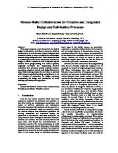
2.3.1 Case A: flywheel cover assembly The first industrial case is a flywheel cover assembly station in an engine assembly plant. In this station the flywheel cover, with a weight of up to 60 kg and a diameter of 0.6 meters, is assembled on the engine block. The current assembly is done by a human using a lifting tool. Figure 1
Current layout of the assembly station of flywheel covers, with operation positions of interest (see online version for colours)
The current layout is presented in Figure 1 with three positions of specific interest: position 1, get flywheel cover from trolley with incoming material; position 2, load and unload flywheel cover in an automated silicone-applying machine; position 3, assemble flywheel cover on an engine block with 12bolts using manually handled nut runners. The three assembly scenarios evaluated in this case are: •
Solely by a human (H): This case represents the current situation. An operator uses a pneumatic lifting device to tilt the product and move it up and down in the z direction. The x and y translation is performed through an overhead rail system and is controlled by force from the operator.
172 •
F. Ore et al. Solely by a robot (R): This scenario represents a system where a robot reaches all the needed positions and does all the assembly handling work.
•
HIRC: In the HIRC situation the simple handling tasks of positions 1 and 2 are performed by the robot. In the assembly situation (position 3) the movements of the product are controlled by the operator through manual force, and the robot acts as a lifting device, carrying the load. The human also returns the robot after assembly to the robotic handling area.
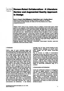
2.3.2 Industrial case B: truck tyre assembly The second industry case is truck tyre assembly, situated at the final assembly line of trucks. The tyre weighs 130 kg and has a diameter of 1.1 metres. Currently the truck tyres are lifted by a pneumatic lifting device and positioned by a human operator. There is one lifting device on each side of the truck chassis. Figure 2
Current layout of the assembly station of truck tyres, only right-hand side lifting tools visible (see online version for colours)
Note: The figure also includes operation positions of interest.
The current assembly layout is presented in Figure 2. In position 1 the tyre is transported to the workstation from the tyre store in the basement through an opening in the floor. The tyre is then assembled on the truck at position 2 with ten nuts with a manually handled nut runner. The truck chassis moves on a continuous driven line and the exact position of the wheel hub where the assembly is performed varies as the truck moves along the line. The three assembly scenarios evaluated in this case are:
HIRC – development and application of simulation software •
173
Solely by a human (H): This case represents the current situation. An operator uses a pneumatic lifting device to lift the product in the up and down (z) direction. The x and y translation is performed through an overhead rail system and is controlled by force from the operator.
•
Solely by a robot (R): This scenario represents a system where a robot reaches all the positions needed and does all the assembly handling work.
•
HIRC: The collaborative implementation in this case includes the robot collecting the tyre at positions 1 and handing over control to the human operator in front of the tyre at position 2. The assembly situation of the tyre is controlled by the operator, who uses the robot as a lifting device. After assembly the robot is automatically returned to collect a new tyre.
3
Results
3.1 Development of the HIRC demonstrator software By combining the functionality in the two software systems (IPS Robotics and IMMA) into one, as described in Figure 3, a HIRC work task can be simulated and analysed. In this research operation time and biomechanical load were chosen as quantitative outputs from the simulation. Figure 3
Illustrating the development of the HIRC demonstrator software (see online version for colours)
174
F. Ore et al.
3.2 Simulation and visualisation of case A: flywheel cover assembly A robot position in the layout was designed where the robot, ABB IRB 6620, reached all the handling positions. The result of this manual layout optimisation is presented in Figure 4. This layout was then used in all simulation scenarios. Figure 4
Optimised layout of the assembly station of case A including the robot, ABB IRB 6620 (see online version for colours)
Figure 5
Screenshot of HIRC assembly operation of case A, created in the demonstrator software (see online version for colours)
The HIRC assembly operation was modelled in the demonstrator software (Figure 5).
3.2.1 Operation time: case A The operation times derived from SAM and robot data are presented in Table 1. In all these time analyses, the times independent of the assembly scenario are not included
HIRC – development and application of simulation software
175
(e.g., operation time of the silicone applying machine). The layout in Figure 1 is used to describe the operations. Operation A1 includes collecting the flywheel cover at position 1. A2 and A3 include the handling to and from the silicone applying machine, and these movements end at a position between 2 and 3 (also called ‘handover position’) where the assembly operation begins. A4 includes the movement to the engine assembly position. A5 returns the robot from the assembly position to the handover position. A6 includes the movement to the robotic home position. Table 1
Operation times in seconds
Operation A1
Get product
Pos.
H
HIRC
R
1
5.8*
2.8
2.8
A2
Product to silicone
1→2
9.2
2.7
2.7
A3
Product from silicone
2→3
5.8
1.4
1.4
A4
Assemble product
3
5.0
4.1
2.0
A5
Empty robot from assembly
3
N.A.*
2.7
2.0
A6
Empty robot home
3→1
N.A.*
0.8
0.8
Σ
25.7
14.5
11.6
Normalised results
100%
56%
45%
Notes: The pos. column represents the positions described in Figure 1 and maps the operations to the layout of the station. *Operation A1 includes moving from assembly position to product.
3.2.2 Biomechanical load: case A A biomechanical load analysis based on the RULA method of the two assembly cases that include humans is presented in Table 2 and Table 3. Table 2 represents the human assembly case and Table 3 the human industrial robot collaborative case. Both these tables present the percentages of movement spent in each RULA score position. Table 2
Biomechanical load analysis for human (H) assembly, based on RULA
Operation
RULA score 1
2
3
4
5
6
7
A1
Get product
0
1
50
49
0
0
0
A2
Product to silicone
0
0
0
39
10
51
0
A3
Product from silicone
0
0
1
64
26
9
0
A4
Assemble product
0
0
13
30
14
43
0
A5
Empty robot from assy.
NA
NA
NA
NA
NA
NA
NA
A6
Empty robot home
NA
NA
NA
NA
NA
NA
NA
Average RULA score
4.5
Notes: The numbers in the table represent the amount of time spent in each RULA score zone in percentages. The average result is a time-weighted average RULA score.
176
F. Ore et al.
Table 3
Biomechanical load analysis for a HIRC assembly, based on RULA
Operation
RULA score 1
2
3
4
5
6
7
A1
Get product
R
R
R
R
R
R
R
A2
Product to silicone
R
R
R
R
R
R
R
A3
Product from silicone
R
R
R
R
R
R
R
A4
Assemble product
0
1
18
41
40
0
0
A5
Empty robot from assy.
0
0
38
38
23
0
0
A6
Empty robot home
R
R
R
R
R
R
R
Average RULA score
4.1
Notes: The numbers in the table represent the amount of time spent in each RULA score zone in percentages. R represents operation performed solely by robot. The average result is a time-weighted average RULA score.
3.3 Simulation and visualisation of case B: truck tyre assembly The position of the robot (ABB IRB 6620) was manually optimised in order to reach all the required handling positions. In this layout it was important to position the robot to make the available robotic workspace as large as possible. The truck chassis moves along a continuously driven line. Figure 6 presents the robot layout that was used in all simulation scenarios. Figure 6
Layout of the assembly station of case B, including the robot, ABB IRB 6620 (see online version for colours)
HIRC – development and application of simulation software Figure 7
177
Screenshot of HIRC assembly operation of case B, created in the demonstrator software (see online version for colours)
The collaborative task in this case (Figure 7) was the last assembly of the tyre on to the wheel hub.
3.3.1 Operation time: case B The operation times derived from SAM and robot data are presented in Table 4. The layout in Figure 2 is used to describe the operations. Operation B1 includes collecting the tyre from the basement opening. B2 includes moving the tyre to a position in front of the axis where it shall be assembled, and B3 is the actual assembly on the axis. B4 includes the return of the tool/robot back to its home position. Table 4
Operation times in seconds Operation
Pos.
H
HIRC
R
1
6.3
0.8
0.8
1→2
2.0
1.9
1.9
2
2.5
5.0
0.9
B1
Get product
B2
Product to front of assy.
B3
Assemble product
B4
Tool back to home
2→1
4.0
2.2
2.2
Σ
14.8
9.8
5.7
Normalised results
100%
67%
39%
Notes: The pos. column represents the positions described in Figure 2 and maps the operations to the layout of the station.
178
F. Ore et al.
3.3.2 Biomechanical load: case B A biomechanical load analysis based on the RULA method of the two assembly cases that include humans is presented in Table 5 and Table 6. Table 5 represents the human assembly case and Table 6 the human industrial robot collaborative case. Both these tables present the percentages of movement spent in each RULA score position. Table 5
Biomechanical load analysis for human (H) assembly, based on RULA RULA score
Operation
1
2
3
4
5
6
7
B1
Get product
0
5
23
73
0
0
0
B2
Product to front of assy.
0
0
100
0
0
0
0
B3
Assemble product
0
0
100
0
0
0
0
B4
Tool back home
0
0
68
32
0
0
0
Average RULA score
3.3
Notes: The numbers in the table represent the amount of time spent in each RULA score zone in percentages. The average result is a time-weighted average RULA score. Table 6
Biomechanical load analysis for a HIRC assembly, based on RULA
Operation
RULA score 1
2
3
4
5
6
7
B1
Get product
R
R
R
R
R
R
R
B2
Product to front of assy.
R
R
R
R
R
R
R
B3
Assemble product
0
0
96
4
0
0
0
B4
Tool back home
R
R
R
R
R
R
R
Average RULA score
3.0
Notes: The numbers in the table represent the amount of time spent in each RULA score zone in percentages. R represents operation performed solely by robot. The average result is a time-weighted average RULA score.
4
Discussion
4.1 Demonstrator software The demonstrator software presented in this paper simulates, visualises and evaluates HIRC. The “...dream combination of human flexibility and machine efficiency” [Tan et al., (2009), p.29], as Tan et al. define HIRC; can be evaluated by numbers from virtual simulations. This software is exemplified by two industrial cases, in both of which the human guides the moving robot, using it as a lifting device. But all levels of collaboration (Schraft et al., 2005; Walther and Guhl, 2014) are possible to simulate in this demonstrator software. In all HIRC there is a need to evaluate the system regarding productivity and ergonomic load, and this is possible with the demonstrator software presented. The demonstrator software presented is based on the IMMA software interface and shares its usability features. User-friendliness and no need of expert knowledge was a
HIRC – development and application of simulation software
179
goal in IMMA development (Hanson et al., 2014). The demonstrator software presented in this paper has not reached this mature level yet, but that is one goal in the future software development. The demonstrator software combines two tools (IMMA and IPS robotics) that are used in industry today and has the potential to be a natural part of future engineering activities in manufacturing organisations. The demonstrator software also facilitates communication between different roles in an organisation that previously may have had difficulties in collaboration, for example ergonomists and robot cell designers and installers. The human motions in the simulation software have not yet been validated. This will be done in future work. Both presented HIRC cases in this paper are to be built in laboratory environments in which the simulated postures are compared with real. The simulation presents one feasible motion for the manikin to perform a task if there exist one. The human is then likely to find one as well; this motion might even be a better one. However, in the presented early evaluation and design are the presented motions used to achieve the biomechanical results. In the following text the industrial cases are discussed with a focus on the production design parameters of operation time and productivity. It is important to emphasise that the aim of this paper is not necessarily to promote the HIRC system, but to show the evaluation possibilities of the proposed software. These evaluations can then be used as a base for decision making on workstation designs in the manufacturing organisation, where HIRC should be seen as one option.
4.2 Evaluation of production design The results from the industrial cases corroborate the assumed benefits of HIRC; the ergonomic situation of the operator is improved and the productivity of the station is increased compared with working without robotic support. A summary of the two production design parameters from the simulated cases, productivity and biomechanical loads, is presented in Figures 8 and 9 and discussed in the subsequent sections. Figure 8
Graph presenting the operation time (in seconds) comparing human, HIRC and robotic assembly in both simulated cases
Operation time (s)
25.7
Human
HIRC
Robot
14.8
14.5 11.6
9.8 5.7
Case A: Flywheel cover assembly
Case B: Tyre assembly
180 Figure 9
F. Ore et al. Graph presenting the RULA score comparing human, HIRC and robotic assembly in both simulated cases
4.5
Human
HIRC
Robot
4.1
RULA score
3.3
0 Case A: Flywheel cover assembly
3
0 Case B: Tyre assembly
4.2.1 Productivity The findings from the two industrial cases show that HIRC systems improve productivity and ergonomic load compared with manual systems. However, if it is possible to automate a station this is always preferable from operation time and biomechanical perspectives, since the robot moves faster than the human and cannot suffer any musculoskeletal injuries. The main advantage of using humans in the operations is to use the flexibility and intelligent decision making of humans, which is superior to that of robots (Krüger et al., 2005). These benefits are difficult for a simulation and visualisation software to evaluate and are not included as parameters in this paper. The main reason why a fully robotised station is not a realistic alternative in either case is the lack of flexibility. In case A two other operators are doing assembly tasks on the engine block simultaneously with the flywheel cover assembly. It is difficult to find a safe assembly sequence for the other operators if the robot moves without human interaction in a shared workspace. In case B the problem is that the hole pattern of the tyre has to match the bolts on the hub of the axis before the assembly. This adjustment is best performed by a human. It is difficult to assess suitable robot axis velocity to use in calculation of robot operational times. In both cases 70% of the presented maximum speed of the robot axis was used. The reduction from full speed represents the acceleration, retardation and lower speeds close to assembly positions resulting from physical robot programming. These numbers can easily be altered to the most appropriate with regard to the specific case. A closer look at the HIRC assembly compared to the manual cases shows a clear productivity improvement, confirming the statement by Krüger et al. (2009) that robots are introduced to increase productivity. HIRC systems yield operation times that only utilise 56% (case A) and 67% (case B) of the time of the manual assembly. The real productivity gains with regard to utilisation of the human operators are even higher, since more time than that is released from the operator performing the assembly task. In case A the human involvement in the assembly task will only be 6.8 seconds compared with 25.7 in the manual case; and in case B the human task in the HIRC case takes 5.0 seconds compared with 14.8 in the fully manual case. In normalised numbers the human time
HIRC – development and application of simulation software
181
used to perform the assembly task is reduced to 26% and 34% of the original manual handling times. These reductions of operation time can in practice result in large improvements of production system throughput. Since productivity in this paper is limited to measuring operational time, factors such as investment, maintenance and energy cost of the robot have not been taken into account. Regardless of whether manual assembly time or operational time is considered, the simulated cases can verify the productivity improvement in HIRC assembly systems compared with manual ones.
4.2.2 Biomechanical load RULA method has been used to evaluate biomechanical load. This focus on the upper body is chosen since the workstations presented are upper body intensive. However other biomechanical evaluation methods, e.g., REBA (Hignett and McAtamney, 2000) or EAVS (Schaub et al., 2013), can be chosen and applied in the analysis. The results from the RULA analysis presented in Figure 9 show that the biomechanical loads on the operators in HIRC assembly stations are slightly lower than in manual assembly. In case A the average RULA scoring is reduced from 4.5 to 4.1 going from manual assembly to HIRC. In case B the reduction is from 3.3 to 3.0. These reductions are small but show in both cases the potential of reducing the strain on the human operator through HIRC assembly stations. The biomechanical result from both these cases correlates with the statement from Oberer-Treitz et al. (2013) on improved ergonomics in HIRC systems. Another improvement in HIRC with regard to biomechanical load is the fact that the manual operator in the HIRC assembly scenarios does less assembly work, compared with the manual case. Tables 1 and 4, show that only 2% (case A) and 34% (case B) of the manual time is used to perform assembly task in a HIRC system. The question that remains to be answered is what other tasks the human will perform in the accumulated time. The time spent on an assembly work task is, however, an important aspect to consider in discussing the difference in biomechanical loads between HIRC assembly systems and manual ones. The original RULA ergonomic evaluation does not consider time as a factor. It only investigates static postures without any consideration of how long the posture is held or how often it is repeated, or operations that may become harmful since they are repeated frequently. However, the average RULA score numbers discussed above are time-weighted RULA scores. They are calculated from RULA scores in Tables 2, 3, 5 and 6 together with the times from Tables 1 and 4. Thus, in this calculation of average RULA scores time is also considered as a factor. There are other biomechanical evaluation methods that include time, and these will in the future be investigated and implemented into the demonstrator software, e.g., OCRA (Occhipinti, 1998) and EAWS (Schaub et al., 2013). According to McAtamney and Corlett, the selection of the posture to be analysed shall “…be made of the posture held for the greatest amount of the work cycle or where highest loads occur” [McAtamney and Corlett, (1993), p.93]. In a computerised simulation the analysis possibilities are greater and more poses are analysed in this paper. This method increases the uncertainties in the quantitative RULA score results, but the results from the analyses can be used to compare risks between workstations investigated.
182
F. Ore et al.
Even though the differences are small between HIRC and manual assembly systems, they still show that the collaborative assembly system has fewer risk factors of future biomechanical load injuries on the operator in these two cases. This lower biomechanical risk also indicates that the HIRC system is better adapted to an elderly workforce since the risk of musculoskeletal injuries increases with age (Fritzsche, 2010).
4.3 Safety The personal safety problem has to be resolved before the HIRC workstations can be implemented in real industrial cases; much research is undertaken and efforts are made to solve these issues. The potential benefits of HIRC systems are huge and the future need of software to simulate collaboration will be strong when the safety issues have been solved. Safety regulations are not considered in this research since current legislation does not allow the physical contact described in the cases. However, future safety regulations need to be possible to include in coming software versions. In this way different safety solutions can also be evaluated. The software can also be used to make risk analyses of possible HIRC workstations. In the case presented, 70% of the maximum speed of the robot is used in the area where the robot moves without human collaboration. These areas are in both cases indicated by a red box in Figure 10. Figure 10 The red box in the two layouts presents the area where the robot works without human collaboration and moves without speed limitations (at 70% of maximum speed) (see online version for colours)
The close distance between the robotic areas and the human working areas highlights the need of advanced safety systems to ensure a safe work environment for the operator, for example by supervising the robotic work area through depth cameras and by introducing a low-speed area in the area close to the human work area.
5
Conclusions
This paper presents demonstrator software developed to simulate HIRC. It is used in two industry cases where a robot assists the human in assembly tasks. The output from the simulation is operation time and biomechanical load on the human. These cases
HIRC – development and application of simulation software
183
verify two of the proposed benefits from literature, that HIRC systems improve productivity and reduce ergonomic loads on the human compared with manual assembly. The demonstrator software will be further developed in the next few years in order to increase its usability.
References Abdel-Malek, K., Yang, J., Marler, T., Beck, S., Mathai, A., Zhou, X., Patrick, A. and Arora, J. (2006) ‘Towards a new generation of virtual humans’, International Journal of Human Factors Modelling and Simulation, Vol. 1, No. 1, pp.2–39. Badler, N.I., Phillips, C.B. and Webber, B.L. (1993) Simulating Humans: Computer Graphics Animation and Control, Oxford University Press, New York. Bohlin, R., Delfs, N., Hanson, L., Högberg, D. and Carlson, J.S. (2012) ‘Automatic creation of virtual manikin motions maximizing comfort in manual assembly processes’, in Hu, J.S. (Ed.): Technologies and Systems for Asssembly Quality, Productivity and Customization: Proceedings of the 4th CIRP Conference on Assembly Technologies and Systems, Ann Arbor, USnited States of America, pp.209–212. Brown, R.G. (2000) ‘Driving digital manufacturing to reality’, Simulation Conference, 2000, Proceedings, Winter, IEEE, pp.224–228. Busch, F., Wischniewski, S. and Deuse, J. (2013) ‘Application of a character animation SDK to design ergonomic human-robot-collaboration’, Proceedings of the 2nd International Digital Human Modeling Symposium, Ann Arbor, USA, pp.1–7. Chryssolouris, G., Mavrikios, D., Papakostas, N., Mourtzis, D., Michalos, G. and Georgoulias, K. (2009) ‘Digital manufacturing: history, perspectives, and outlook’, Proceedings of the Institution of Mechanical Engineers, Part B: Journal of Engineering Manufacture, Vol. 223, No. 5, pp.451–462. Fischer, M. and Henrich, D. (2009) ‘3D collision detection for industrial robots and unknown obstacles using multiple depth images’, in Kröger, T. and Wahl, F. (Eds.): Advances in Robotics Research: Theory, Implementation, Application, pp.111–122, Springer, Berlin. Fortin, C., Gilbert, R., Beuter, A., Laurent, F., Schiettekatte, J., Carrier, R. and Dechamplain, B. (1990) ‘SAFEWORK: a microcomputer-aided workstation design and analysis. New advances and future developments’, in Karwowski, W., Genaidy, A.M. and Asfour, S. (Eds.): Computer-Aided Ergonomics: A Researcher’s Guide, pp.157–180, Taylor & Francis, London. Fritzsche, L. (2010) ‘Ergonomics risk assessment with digital human models in car assembly: simulation versus real life’, Human Factors and Ergonomics in Manufacturing & Service Industries, Vol. 20, No. 4, pp.287–299. Hanson, L., Högberg, D., Bohlin, R. and Carlsson, J.S. (2011) ‘IMMA – intelligently moving manikins – project status 2011’, Proceedings of the 1st International Symposium on Digital Human Modeling, Lyon, France, 14–16 June, pp.1–5. Hanson, L., Högberg, D., Carlson, J.S., Bohlin, R., Brolin, E., Delfs, N., Mårdberg, P., Gustafsson, S., Keyvani, A. and Rhen, I-M. (2014) ‘IMMA – intelligently moving manikins in automotive applications’, Paper presented at 3rd International Summit on Human Simulation (ISHS 2014), 20–22 May, Tokyo, Japan. Hanson, L., Sperling, L., Gard, G., Ipsen, S. and Olivares Vergara, C. (2009) ‘Swedish anthropometrics for product and workplace design’, Applied Ergonomics, Vol. 40, No. 4, pp.797–806. Hignett, S. and McAtamney, L. (2000) ‘Rapid entire body assessment (REBA)’, Applied Ergonomics, Vol. 31, No. 2, pp.201–205. ISO International Organization for Standardisation (2011a) EN-ISO10218-1:2011 Robots and Robotic Devices – Safety Requirements for Industrial Robots – Part 1: Robots and Robotic Devices – Safety Requirements for Industrial Robots, ISO, Geneva.
184
F. Ore et al.
ISO International Organization for Standardisation (2011b) EN-ISO10218-2:2011 Robots and Robotic Devices – Safety Requirements for Industrial Robots – Part 2: Robot Systems and Integration, ISO, Geneva. Klingstam, P. and Gullander, P. (1999) ‘Overview of simulation tools for computer-aided production engineering’, Computers in Industry, Vol. 38, No. 2, pp.173–186. Krüger, J., Lien, T.K. and Verl, A. (2009) ‘Cooperation of human and machines in assembly lines’, CIRP Annals – Manufacturing Technology, Vol. 58, No. 2, pp.628–646. Krüger, J., Nickolay, B., Heyer, P. and Seliger, G. (2005) ‘Image based 3D surveillance for flexible man-robot-cooperation’, CIRP Annals – Manufacturing Technology, Vol. 54, No. 1, pp.19–22. Laring, J., Forsman, M., Kadefors, R. and Örtengren, R. (2002) ‘MTM-based ergonomic workload analysis’, International Journal of Industrial Ergonomics, Vol. 30, No. 3, pp.135–148. Lee, D.M.A. and ElMaraghy, W.H. (1990) ‘ROBOSIM: a CAD-based off-line programming and analysis system for robotic manipulators’, Computer-Aided Engineering Journal, Vol. 7, No. 5, pp.141–148. Luh, J.Y.S. and Srioon, S. (2000) ‘Animated simulation of human-robot interactions’, Proceedings of the 3rd World Congress on Intelligent Control and Automation, Hefei, People’s Republic of China, pp.1361–1366. Maynard, H.B., Stegemerten, G.J. and Schwab, J.L. (1948) Methods Time Measurement, McGrawHill, New York. McAtamney, L. and Corlett, E.N. (1993) ‘RULA: a survey method for the investigation of workrelated upper limb disorders’, Applied Ergonomics, Vol. 24, No. 2, pp.91–99. Morioka, M. and Sakakibara, S. (2010) ‘A new cell production assembly system with human-robot cooperation’, CIRP Annals – Manufacturing Technology, Vol. 59, No. 1, pp.9–12. Mourtzis, D., Papakostas, N., Mavrikios, D., Makris, S. and Alexopoulos, K. (2015) ‘The role of simulation in digital manufacturing: applications and outlook’, International Journal of Computer Integrated Manufacturing, Vol. 28, No. 1, pp.3–24. Oberer-Treitz, S., Dietz, T. and Verl, A. (2013) ‘safety in industrial applications: from fixed fences to direct interaction’, 44th International Symposium on Robotics (ISR), Seoul, Korea, 24–26 October, pp.1–4. Occhipinti, E. (1998) ‘OCRA: a concise index for the assessment of exposure to repetitive movements of the upper limbs’, Ergonomics, Vol. 41, No. 9, pp.1290–1311. Pan, Z., Polden, J., Larkin, N., van Duin, S. and Norrish, J. (2012) ‘Recent progress on programming methods for industrial robots’, Robotics and Computer-Integrated Manufacturing, Vol. 28, No. 2, pp.87–94. Pedrocchi, N., Vicentini, F., Matteo, M. and Tosatti, L. M. (2013) ‘Safe human-robot cooperation in an industrial environment’, International Journal of Advanced Robotic Systems, Vol. 10 [online] doi: 10.5772/53939 (accessed 11 September 2013). Rasmussen, J., Damsgaard, M., Surma, E., Christensen, S. T., de Zee, M. and Vondrak, V. (2003) ‘AnyBody – a software system for ergonomic optimization’, Fifth World Congress on Structural and Multidisciplinary Optimization (WCSMO5), Venice, Italy, 19–23 May. Rasmussen, J., Vondrak, V., Damsgaard, M., De Zee, M., Christensen, S.T. and Dostal, Z. (2002) ‘The any body project – computer analysis of the human body’, in Jelen, K., Kušová, S., Chalupová, M. and Otáhal, J. (Eds.): Proceedings of International Conference on Biomechanics of Man, November, pp.270–274. Salmi, T., Väätäinen, O., Malm, T., Montonen, J. and Marstio, I. (2014) ‘Meeting new challenges and possibilities with modern robot safety technologies’, in Zaeh, M. (Ed.): Enabling Manufacturing Competitiveness and Economic Sustainability. Proceedings of the 5th International Conference on Changeable, Agile, Reconfigurable and Virtual Production (CARV 2013), Springer, pp.183–188. Schaub, K., Caragnano, G., Britzke, B. and Bruder, R. (2013) ‘The European assembly worksheet’, Theoretical Issues in Ergonomics Science, Vol. 14, No. 6, pp.616–639.
HIRC – development and application of simulation software
185
Schmidt, B. and Wang, L. (2012) ‘Active collision avoidance for human-robot collaborative manufacturing’, in Björkman, M. (Ed.): Proceedings of the 5th International Swedish Production Symposium, SPS12, pp.81–86. Schraft, R.D., Meyer, C., Parlitz, C. and Helms, E. (2005) ‘PowerMate – a safe and intuitive robot assistant for handling and assembly tasks’, Proceedings of the 2005 IEEE International Conference on Robotics and Automation, 2005. ICRA 2005, pp.4074–4079. Segeborn, J., Segerdahl, D., Ekstedt, F., Carlson, J.S., Andersson, M., Carlsson, A. and Söderberg, R. (2014) ‘An industrially validated method for weld load balancing in multi station sheet metal assembly lines’, Journal of Manufacturing Science and Engineering, Vol. 136, No. 1, pp.1–7. Seidl, A. (1997) RAMSIS – A New CAD-Tool for Ergonomic Analysis of Vehicles Developed for the German Automotive Industry, SAE Technical Paper 970088 [online] doi: 10.4271/970088 (accessed 11 September 2013). Tan, J.T.C., Duan, F., Zhang, Y., Watanabe, K., Kato, R. and Arai, T. (2009) ‘Human-robot collaboration in cellular manufacturing: design and development’, Proceedings of the IEEE/RSJ International Conference on Intelligent Robots and Systems, IROS 2009, pp.29–34. United Nations (2013) World Population Prospects: The 2012 Revision, Highlights and Advance Tables, Working Paper ESA/P/WP.228 [online] http://esa.un.org/unpd/wpp/Documentation/ pdf/WPP2012_highlights.pdf (accessed 8 November 2013). Vollmann, K. (2002) ‘A new approach to robot simulation tools with parametric components’, 2002 IEEE International Conference on Industrial Technology, ICIT ‘02, Vol. 2, pp.881–885. Walther, S. and Guhl, T. (2014) ‘Classification of physical human-robot interaction scenarios to identify relevant requirements’, Proceedings of the 41st International Symposium on Robotics, ISR/Robotik 2014, pp.1–8. Wan, D., Hui, L. and Xiaoting, T. (2007) ‘Off-line programming of spot-weld robot for car-body in white based on Robcad’, Proceedings of the International Conference on Mechatronics and Automation, ICMA 2007, Harbin, People’s Republic of China, pp.763–768. Yap, H.J., Taha, Z., Md Dawal, S.Z. and Chang, S-W. (2014) ‘Virtual reality based support system for layout planning and programming of an industrial robotic work cell’, PLoS ONE, Vol. 9 [online] doi: 10.1371/journal.pone.0109692 (accessed 7 January 2015). Zwicker, C. and Reinhart, G. (2013) ‘Human-robot-collaboration system for a universal packaging cell for heavy electronic consumer goods’, in Zaeh, M.F. (Ed.): Enabling Manufacturing Competitiveness and Economic Sustainability: Proceedings of the 5th International Conference on Changeable, Agile, Reconfigurable and Virtual Production (CARV 2013), Springer, pp.195–199.