Signal & Image Processing : An International Journal(SIPIJ) Vol.2, No.1, March 2011
HYBRID JPEG COMPRESSION USING EDGE BASED SEGMENTATION M.Mohamed Sathik1 , K.Senthamarai Kannan2 and Y.Jacob Vetha Raj3 1
Department of Computer Science, Sadakathullah Appa College, Tirunelveli, India
[email protected]
2,3
Department of Statistics, Manonmanium Sundaranar University, Tirunelveli, India
[email protected] [email protected]
Abstract : A hybrid image compression method is proposed in this paper which segments the image into background and foreground and compress them with different quality levels.. The foreground of the image is given more importance than the background. An edge based segmentation method is used to segment the image into foreground area and background area. The proposed method highly preserves quality of the foreground image. JPEG compression is a widely used compression technique. Normally the JPEG compression method uses linear quantization and threshold values to maintain certain quality level in an entire image. The proposed method adapts variable quantization and threshold values corresponding to background and foreground. This ensures that the vital area of the image is highly preserved than the other areas of the image. This hybrid approach increases the compression ratio and produces a desired high quality compressed image. Key Words: Image Compression, Image Transform, Quantization, Edge-Detection and Segmentation.
1. INTRODUCTION Image compression is an inevitable solution for image transmission since the channel bandwidth is limited and the demand is for faster transmission. Storage limitation is also forcing to go for image compression as the color resolution and spatial resolutions are increasing according to quality requirements. A huge amount of online information is used either graphical or pictorial in nature. The requirements for storage and communications are high. Compressing the data is one of the way out for this problem. Thus the methods of compressing the data prior to storage and/or transmission are of essential real-world and viable concern. Lossless and lossy Compression techniques are the two broad classes of image compression. The lossless compression is particularly beneficial in image archiving and permits the image to be compressed and decompressed without dropping any data. And the lossy compression, affords higher levels of compression ratio but result in a less than perfect replica of the original image. Lossy compression is beneficial in applications such as television transmission, videoconferencing, and facsimile transmission etc., in these circumstances certain amount of error is tolerable. The principal aim of image compression is to reduce the number of bits required to represent an image. In lossless image compression algorithms, the reconstructed image is identical to the original image. Lossless algorithms, however, are limited by the low compression ratios they can attain. Lossy compression algorithms, on the other hand, are capable of attaining high compression ratios. Though the reconstructed image is not identical to the original image, lossy compression algorithms attain high compression ratios by exploiting human visual properties.
DOI : 10.5121/sipij.2011.2112
165
Signal & Image Processing : An International Journal(SIPIJ) Vol.2, No.1, March 2011
Wavelet transformation(WT) [1], [5]-[10], vector quantization(VQ) [4],[5] approaches are generally used in addition to numerous other methods[11]-[17] in image compression. The problem in lossless compression method is that, the compression ratio is very less; where as in the lossy compression the compression ratio is very high but may loose vital information of the image. Hybrid image compression [18]-[19] incorporate diverse compression systems like PVQ and DCTVQ in a single image compression. The proposed method uses lossy compression method with various quality levels based on the context to compress a single image by eluding the complications of using side information for image decompression in [20]. The proposed method achieves a hybrid compression, which makes a balance on compression ratio and image quality by compressing the vital portions of the image with high quality. In this approach the main subject in the image is very significant than the background image. Considering the significance of image constituents, and the influence of smoothness in image compression, this technique segments the image as main subject and background, then the background of the image is imperiled to low quality lossy compression and the main subject is compressed with high quality lossy compression. There are numerous amount of work on image compression is carried out both in lossless [1] [14] [17] and lossy [4] [15] compression. Very limited research works are carried out for Hybrid Image compression [18]-[20]. In the proposed work, for image compression, the edge detection, segmentation, smoothing and dilation techniques are used. For edge detection, segmentation [21],[22] smoothing and dilation, numerous works have been carried out [2],[3]. Some of the works related to this paper is described in section 2. A novel and a time efficient method to detect edges and segmentation used in the proposed work are described in section 3, section 4 gives a detailed description of the proposed method, the results and discussion are given in section 5 and the concluding remarks are given in section 6.
2.RELATED WORK Charles F. Hall (1985) proposed a Hybrid Image Compression Technique based on several studies that have shown that, the presence of edges is important to the overall subjective quality of the image [26]. High contrast edge information can be isolated in upper bit plane of most types of imagery. Simple run length encoding of this bit plane can be used to preserve the location and approximate peak amplitude of the edge information at an overhead cost of less than 0.1 bit/pixel. When upper bit plane run length encoding is combined with standard transform or DPCM coding, the resultant hybrid technique provides images with subjective quality improvements of better than two to one. Jiangtau Men and Xrlelong Zhu (1995) proposed a novel DCT and FTC hybrid image compression algorithm, which dramatically improves the speed of FTC coding and JPEGS ability of preserving image details at high compression ratios [27]. The overall subjective quality of the whole JPEG decoded image is also heightened S.W.Hong and P.Bao (2000) proposed a Hybrid image compression model based on subband coding and edge-preserving regularization [20]. The idea is to incorporate the technique of image restoration into the current lossy image compression schemes. The model utilizes the edge information extracted from the source image as a priori knowledge for the subsequent reconstruction. The model incorporated with SPIHT (set partitioning in hierarchical trees) outperformed the original SPIHT. G.Farhadi (2003) proposed a Hybrid Image Compression Scheme Using Block Based Fractal Coding and DCT [28]. These hybrid algorithms outperform pure fractal coders and show better behavior as compared to both pure fractal and DCT-based coders. In our earlier work a Hybrid Image Compression by Blurring
166
Signal & Image Processing : An International Journal(SIPIJ) Vol.2, No.1, March 2011
Background and Non-Edges is proposed where the edges and foreground information are highly preserved and compression ratio is increased [22].
3. BACKGROUND 3.1 JPEG Compression JPEG Compression method is one of the commonly recognized and used procedures for image compression. The constituents and ideologies behind this method are described in the subsequent subsections. 3.1.1 Constituents of JPEG Image Compression System. The JPEG Image compression system consists of three closely connected constituents specifically • Source encoder (DCT based) • Quantizer • Entropy encoder
3.1.2 Ideologies behind JPEG Compression. A common characteristic of most images is that the nearby pixels are associated and therefore comprise redundant information. The primary task then is to find less associated representation of the image. Two essential attributes of compression are redundancy and irrelevancy reduction. Redundancy reduction aims at removing repetition from the signal source. Irrelevancy reduction omits parts of the signal that will not be discerned by the signal receiver, namely the Human Visual System (HVS). The JPEG compression standard employs the use of the discrete cosine transform(DCT), which is applied to each 8 x 8 block of the subdivided image. Compression is then realized by performing quantization of each of those 8 x 8 coefficient blocks.
3.1.3 Image Transform Coding For JPEG Compression Algorithm. In the image compression algorithm, the input image is subdivided into 8-by-8 or 16-by-16 nonoverlapping blocks, and the two-dimensional DCT is calculated for each block. The DCT coefficients are then quantized, coded, and transmitted. The JPEG receiver decodes the quantized DCT coefficients, calculates the inverse two-dimensional DCT of each block, and then puts the blocks back unruffled into a single image. For typical images, many of the DCT coefficients have values near to zero; these coefficients can be cast-off without seriously disturbing the quality of the reconstructed image. A two dimensional DCT of an M by N matrix A is defined as given in eqn(2): M-1 N-1
Bpq = αpαq ∑ ∑ Amn cos m=0 n=0
π (2m +1)p 2M
cos
π (2n +1)q 2N
, 0 ≤ p ≤ M-1 0 ≤ q ≤ N-1
…(1)
where
αp = 1/2/MM ,, 1p≤=p0≤ M-1
167
Signal & Image Processing : An International Journal(SIPIJ) Vol.2, No.1, March 2011
αq = 1/2/NN ,, 1q≤=q0≤ N-1
The DCT is an invertible transformation and its inverse is given in eqn(2)
M-1 N-1
Amn = αpαq ∑ ∑ Bpq cos
π (2m +1)p 2M
m=0 n =0
cos
π (2n +1)q 2N
, 0 ≤ p ≤ M-1 0 ≤ q ≤ N-1
…(2)
Where
αp = 1/2/MM ,, 1p≤=p0≤ M-1
αq = 1/2/NN ,, 1q≤=q0≤ N-1
8 X 8 blocks FDC T
Quantizer
Quantizing Table
Source image
Entropy Encoder
Compressed image data
Huffman Table
Figure 1 JPEG Encoder Block Diagram
Compressed Image data
Entropy Decoder
Dequantizer
Quantizer Table
IDCT
Huffman Table
Reconstructe d Image
Figure 2 JPEG Decoder Block Diagram The DCT based encoder can be thought of as basically compression of a stream of 8 X 8 blocks of image sections. Each 8 X 8 block makes its way through each processing step, and produces output in compressed form into the data stream. Because nearby image pixels are highly 168
Signal & Image Processing : An International Journal(SIPIJ) Vol.2, No.1, March 2011
associated, the ‘forward’ DCT (FDCT) processing step lays the foundation for accomplishing data compression by concentrating most of the signal in the lower spatial frequencies. For a typical 8 X 8 sample block from a classic source image, most of the spatial frequencies have zero or near-zero amplitude and need not be encoded. In principle, the DCT presents no loss to the source image samples; it purely transforms them to a realm in which they can be more competently encoded. After output from the FDCT, each of the 64 DCT coefficients are uniformly quantized in aggregation with a carefully designed 64 – element Quantization Table. At the decoder, the quantized values are multiplied by the respective QT elements to recover the original values. After quantization, all of the quantized coefficients are well-arranged into the “zig-zag” sequence. This arrangement helps to facilitate entropy encoding by assigning low-frequency non-zero coefficients before high-frequency coefficients. The DC coefficient, which contains a significant fraction of the complete image energy, is differentially encoded.
DC
AC01
AC07
AC77 Figure 3 Zig-Zag Arrangement. 3.2 Edge Detection A matrix ‘M’ of order m x n is used to represent the image of width n and height m. The possible values for Mi,j are in the range [0,255] , for any i=1..m, any j=1..n. Let G be a matrix of the equal order as of ‘M’ for storing the gradient value, with a range of [0,255]. Let E be a binary matrix of the equal order as of ‘M’ and storing the brand of the pixel if it is in edge or not, if it is in edge the value 1 is assigned otherwise 0 is assigned. The edge detection is accomplished by determining the maximum gradient value of a pixel from its three adjacent pixels as shown in Figure 1. If the maximum value of the gradients fulfills certain prerequisite then the corresponding pixel is considered to be in edge. The computation to detect whether a pixel Mi,j at (i,j) is in edge or not is given in equations (1) and (2).
Mi,j Mi+1,j
Mi,j+1 Mi+1,j+1
Figure 1- Nearby Pixels 169
Signal & Image Processing : An International Journal(SIPIJ) Vol.2, No.1, March 2011
Gi,j=max{|Mi,j–Mi+1,j|,|Mi,j–Mi+1,j+1|,|Mi,j–Mi,j+1 |}
1 if G ij > τ Eij = 0 otherwise
…(1) …(2)
where τ is a predefined threshold value. Here a threshold value is carefully taken empirically, and the precondition to a pixel Mi,j at (i,j) to be in edge is that the value of Gi,j must be greater than the threshold, otherwise the pixel is believed to be in non-edge area. There are many prevailing edge detection techniques like Sobel, Canny, Roberts, etc are considering 8-neighbours of a pixel to resolve if the pixel is on edge or not. This novel method considers only 3-neighbours of a pixel to resolve if the pixel is on edge or not which decreases the computation time.
3.3. Segmentation The segmentation of foreground and background image is computed after detecting the edges as per Section-2.2. The scan line algorithm is applied to fill in the space surrounded by the edges. The horizontal and vertical scanning is made individually and the result is combined to get the foreground image. In horizontal scan line process, the scanning starts from left to right to find non-zero value in the matrix E. For scanning a line or row i, the column j varies from 1 towards n, and test for non-zero value in Ei,j , when non zero value of Ei,j is found, set j as the starting column Λ , now the scan proceeds from right to left to find the right most edge pixel, the column starts from n towards 1 to find a non-zero element at row i, when the non-zero Eij is found ,set j as the ending column Ω . Now fill the line from Ei, Λ to Ei, Ω . After iterating the process for all the rows in the image, the horizontally filled image would be ready, in the same way vertical scan line process starts from top to bottom that is keeping the column fixed and change the row from 1 to m. After finishing vertical scan line procedure, the two images are combined by logical AND operation. The resultant image is a binary image in which the foreground is denoted by 1 and the background is denoted by 0. The segmented image is used in the proposed algorithm to resolve whether to compress a pixel using high quality compression or not.
4. PROPOSED HYBRID IMAGE COMPRESSION METHOD The input image is initially segmented into background and foreground portions as described in section 2.2. Then the image is subdivided into 8x8 blocks and DCT coefficients are computed for each block. The quantization is performed conferring to quantization table. The quantized values are then rearranged according to zig-zag arrangement as described in section 3.1.3. The lesser values are discarded from the list in the zig-zag arrangement by the selector as per the block’s presences recognized by the classifier. If the block is being present in foreground area then the threshold level is set to high by the selector, otherwise a lower value for threshold is set by the selector. After discarding insignificant coefficients the remaining coefficients are compressed by the typical entropy encoder based on the code table. Algorithm
1. 2. 3. 4. 5.
Input the image to be compressed. Segment the input image into background and foreground based on edges. Subdivide the input image into 8x8 blocks. Find the DCT coefficients for each block. Quantize the DCT coefficients based on quantization table. 170
Signal & Image Processing : An International Journal(SIPIJ) Vol.2, No.1, March 2011
6. 7.
Discard lower quantized values depend on the threshold value selected by the selector. Compress remaining quantized values by Entropy Encoder
The architecture of the proposed method is presented in figure 5. The Quantization table is a conventional table derived from experimental results. The Quantizer quantizes the DCT coefficients calculated by FDCT. The classifier identifies the type of each pixel by segmenting the given input image. Both the selector and limiter participate together to find the discard threshold value. The entropy encoder generates compressed code using the Code Table. The compressed cade may be stored or transmitted.
Quantizing Table
Input Image Classifier
FDCT
Quantizer
Selector
Limiter
Code Table
Entropy Encoder Compressed Image
Figure – 5. Architecture of Hybrid JPEG Compression
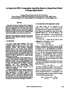
5. RESULTS AND DISCUSSION The Hybrid JPEG Compression Using Edge Based Segmentation method is implemented according to the description in section 4 and verified with a set of test images shown in figure 6. The outcomes obtained from the implementation of the proposed algorithm are shown in figures 6, 8, 9 and table 1. Figure 7.a shows the original input image. In Figure 7.b the white area shows the detected edges and in Figure 7.c the white area shows the foreground area. The compressed bit rates of the twelve test images are calculated and presented in table 1. The compression ratio (CR) is rounded to two decimal points for compact tabulation. The PSNR@MainSubject column shows the PSNR values common to both Hybrid Image Compression Method and JPEG compression. Since the main subject is compressed using constraints to get best possible quality in Hybrid Image Compression, both Hybrid Compression Method and JPEG compression gives the same PSNR value at main subject area. Since the PSNR values at the background area in the hybrid compressed images are lower than the High Quality(HQ) JPEG compressed images the overall PSNR values for hybrid compressed images are lower than High Quality(HQ) JPEG compressed images. In both HQ JPEG and hybrid
171
Signal & Image Processing : An International Journal(SIPIJ) Vol.2, No.1, March 2011
compressed images the main subject is equally preserved thus giving the same PSNR values at main subject area.
Figure – 6 Test Images (1-12 from left to right and top to bottom)
a)Input Image
172
Signal & Image Processing : An International Journal(SIPIJ) Vol.2, No.1, March 2011
b) Edges of Input Image
c)Segmented Main Subject Area Figure – 7 Input /Output
173
Signal & Image Processing : An International Journal(SIPIJ) Vol.2, No.1, March 2011
Table -1 Compression Ratio and PSNR values attained by Hybrid JPEG and JPEG Hybrid HQ LQ PSNR@ PSNR@ Main Sl Main PSNR Subject CR PSNR CR PSNR Subject No CR 1 4.34 29.40 30.85 3.27 29.98 28.73 22.58 22.86 2 2.98 25.14 30.48 2.75 30.40 17.65 19.25 20.14 3 7.69 27.36 28.97 3.68 28.14 26.64 21.91 22.34 4 4.84 37.13 38.50 3.93 37.49 25.72 24.80 25.54 5 3.43 28.38 32.03 2.81 31.52 23.76 20.81 21.31 6 12.74 31.75 41.80 3.38 34.14 30.05 27.74 29.71 7 5.94 32.71 33.54 5.51 33.27 29.81 25.95 26.19 8 2.68 26.11 26.53 2.53 26.44 25.56 19.58 19.68 9 7.71 30.75 35.97 4.92 33.86 29.53 25.96 27.18 10 4.53 30.06 31.14 4.00 30.78 25.84 22.52 22.73 11 4.34 30.81 27.49 3.38 30.30 26.90 22.38 23.26 12 11.34 29.14 39.02 4.33 36.13 31.50 26.49 29.72
Compression Ratio
14 12 10 8 6 4 2 0 1
2
3
4
5
6
7
8
9
10
11
12
Images Hybrid JPEG
JPEG
Figure – 8 Compression Ratios Attained for Test Images
6. CONCLUSION The compression ratio of Hybrid method is better than JPEG method in all of the test cases. In the worst case both Hybrid and JPEG method gives the same compression ratio. The PSNR value at the main subject area is equal for both the methods. The PSNR value at the background area is lower in Hybrid method which is acceptable, since the background area is not considered to be so 174
Signal & Image Processing : An International Journal(SIPIJ) Vol.2, No.1, March 2011
important. The Hybrid method is appropriate for imagery with larger inconsequential background and certain level of loss is tolerable in the background of the image.
REFERENCES Xiwen OwenZhao, Zhihai HenryHe, “Lossless Image Compression Using Super-Spatial Structure Prediction”, IEEE Signal Processing Letters, vol. 17, no. 4, April 2010 383 [2] Aaron T. Deever and Sheila S. Hemami, “Lossless Image Compression With Projection-Based and Adaptive Reversible Integer Wavelet Transforms”, IEEE Transactions on Image Processing, vol. 12, NO. 5, May 2003. [3] Nikolaos V. Boulgouris, Dimitrios Tzovaras, and Michael Gerassimos Strintzis, “Lossless Image Compression Based on OptimalPrediction, Adaptive Lifting, and Conditional Arithmetic Coding”, IEEE Transactions on Image Processing, vol. 10, NO. 1, Jan 2001 [4] Xin Li, , and Michael T. Orchard “ Edge-Directed Prediction for Lossless Compression of Natural Images”, IEEE Transactions on Image Processing, vol. 10, NO. 6, Jun 2001. [5] Jaemoon Kim, Jungsoo Kim and Chong-Min Kyung , “A Lossless Embedded Compression Algorithm for High Definition Video Coding” 978-1-4244-4291 / 09 2009 IEEE. ICME 2009 [6] Rene J. van der Vleuten, Richard P.Kleihorstt ,Christian Hentschel,t “Low-Complexity Scalable DCT Image Compression”, 2000 IEEE. [7] K.Somasundaram, and S.Domnic, “Modified Vector Quantization Method for mage Compression”, ’Transactions On Engineering, Computing And Technology Vol 13 May 2006 [8] Mohamed A. El-Sharkawy, Chstian A. White and Harry ,”Subband Image Compression Using Wavelet Transform And Vector Quantization”, 1997 IEEE. [9] Amir Averbuch, Danny Lazar, and Moshe Israeli ,”Image Compression Using Wavelet Transform and Multiresolution Decomposition”, IEEE Transactions on Image Processing, vol. 5, NO. 1, Jan 1996. [10] Jianyu Lin, Mark J. T. Smith,” New Perspectives and Improvements on the Symmetric Extension Filter Bank for Subband /Wavelet Image Compression”, IEEE Transactions on Image Processing, vol. 17, NO. 2, Feb 2008. [11] Yu Liu, Student Member, and King Ngi Ngan, “Weighted Adaptive Lifting-Based Wavelet Transform for Image Coding “,IEEE Transactions on Image Processing, vol. 17, NO. 4, Apr 2008. [12] Michael B. Martin and Amy E. Bell, “New Image Compression Techniques Using Multiwavelets and Multiwavelet Packets” ,IEEE Transactions on Image Processing, vol. 10, NO. 4, Apr 2001. [13] Roger L. Claypoole, Jr , Geoffrey M. Davis, Wim Sweldens ,“Nonlinear Wavelet Transforms for Image Coding via Lifting” , IEEE Transactions on Image Processing, vol. 12, NO. 12, Dec 2003. [14] David Salomon, “Data Compression , Complete Reference”, Springer-Verlag New York, Inc, ISBN 0-387-40697-2. [15] Eddie Batista de Lima Filho, Eduardo A. B. da Silva Murilo Bresciani de Carvalho, and Frederico Silva Pinagé “Universal Image Compression Using Multiscale Recurrent Patterns With Adaptive Probability Model” , IEEE Transactions on Image Processing, vol. 17, NO. 4, Apr 2008. [16] Ingo Bauermann, and Eckehard Steinbach, “RDTC Optimized Compression of Image-Based Scene Representations (Part I): Modeling and Theoretical Analysis” , IEEE Transactions on Image Processing, vol. 17, NO. 5, May 2008. [17] Roman Kazinnik, Shai Dekel, and Nira Dyn , ”Low Bit-Rate Image Coding Using Adaptive Geometric Piecewise Polynomial Approximation”, IEEE Transactions on Image Processing, vol. 16, NO. 9, Sep 2007. [18] Marta Mrak, Sonja Grgic, and Mislav Grgic ,”Picture Quality Measures in Image Compression Systems”, EUROCON 2003 Ljubljana, Slovenia, 0-7803-7763-W03 2003 IEEE. [19] Alan C. Brooks, Xiaonan Zhao, , Thrasyvoulos N. Pappas., “Structural Similarity Quality Metrics in a Coding Context: Exploring the Space of Realistic Distortions”, IEEE Transactions on Image Processing, vol. 17, no. 8, pp. 1261–1273, Aug 2008. [20] Hong, S. W. Bao, P., “Hybrid image compression model based on subband coding and edgepreserving regularization”, Vision, Image and Signal Processing, IEE Proceedings, Volume: 147, Issue: 1, 16-22, Feb 2000 [21] Zhe-Ming Lu, Hui Pei ,”Hybrid Image Compression Scheme Based on PVQ and DCTVQ “,IEICE - Transactions on Information and Systems archive, Vol E88-D , Issue 10 ,October 2006 [1]
175
Signal & Image Processing : An International Journal(SIPIJ) Vol.2, No.1, March 2011 Y.Jacob Vetha Raj, M.Mohamed Sathik and K.Senthamarai Kanna,, “Hybrid Image Compression by Blurring Background and Non-Edges. The International Journal on Multimedia and its application .Vol 2, No.1, February 2010, pp 32-41 [23] Willian K. Pratt ,”Digital Image Processing” ,John Wiley & Sons, Inc, ISBN 9-814-12620-9. [24] Jundi Ding, Runing Ma, and Songcan Chen,”A Scale-Based Connected Coherence Tree Algorithm for Image Segmentation”, IEEE Transactions on Image Processing, vol. 17, NO. 2, Feb 2008. [25] Kyungsuk (Peter) Pyun, , Johan Lim, Chee Sun Won, and Robert M. Gray, “Image Segmentation Using Hidden Markov Gauss Mixture Models”, ” ,IEEE Transactions on Image Processing, VOL. 16, NO. 7, JULY 2007 [26] Charles F. Hall., “A Hybrid Image Compression Technique” CH2I 18-8/85/0000-0149 © 1985 IEEE [27] Jiangtau Men and Xrlelong Zhu, “A Novel DCT AND FrC Based Hybrid Still Image Compression Algorithm”, 0-7803-2516-8195 © 1995 IEEE [28] G.Farhadi , “A Hybrid Image Compression Scheme Using Block Based Fractal Coding And DCT, EC-VIP-MC 2003,4th EURASIP. [22]
176